EP0450124B1 - Four pour la fabrication d'une préforme en quartz de haute pureté - Google Patents
Four pour la fabrication d'une préforme en quartz de haute pureté Download PDFInfo
- Publication number
- EP0450124B1 EP0450124B1 EP90106551A EP90106551A EP0450124B1 EP 0450124 B1 EP0450124 B1 EP 0450124B1 EP 90106551 A EP90106551 A EP 90106551A EP 90106551 A EP90106551 A EP 90106551A EP 0450124 B1 EP0450124 B1 EP 0450124B1
- Authority
- EP
- European Patent Office
- Prior art keywords
- muffle tube
- partition
- preform
- heating furnace
- glass preform
- Prior art date
- Legal status (The legal status is an assumption and is not a legal conclusion. Google has not performed a legal analysis and makes no representation as to the accuracy of the status listed.)
- Expired - Lifetime
Links
- VYPSYNLAJGMNEJ-UHFFFAOYSA-N Silicium dioxide Chemical compound O=[Si]=O VYPSYNLAJGMNEJ-UHFFFAOYSA-N 0.000 title claims description 16
- 238000005192 partition Methods 0.000 claims description 73
- 238000010438 heat treatment Methods 0.000 claims description 58
- OKTJSMMVPCPJKN-UHFFFAOYSA-N Carbon Chemical compound [C] OKTJSMMVPCPJKN-UHFFFAOYSA-N 0.000 claims description 34
- 229910052799 carbon Inorganic materials 0.000 claims description 33
- 239000011521 glass Substances 0.000 claims description 32
- 238000000638 solvent extraction Methods 0.000 claims 1
- IJGRMHOSHXDMSA-UHFFFAOYSA-N Atomic nitrogen Chemical compound N#N IJGRMHOSHXDMSA-UHFFFAOYSA-N 0.000 description 31
- 239000007789 gas Substances 0.000 description 26
- 239000012298 atmosphere Substances 0.000 description 21
- 239000005373 porous glass Substances 0.000 description 18
- 239000013307 optical fiber Substances 0.000 description 14
- 229910001873 dinitrogen Inorganic materials 0.000 description 13
- 238000010926 purge Methods 0.000 description 10
- 229910052757 nitrogen Inorganic materials 0.000 description 9
- 238000007669 thermal treatment Methods 0.000 description 9
- 238000007254 oxidation reaction Methods 0.000 description 7
- 230000003647 oxidation Effects 0.000 description 6
- 230000000052 comparative effect Effects 0.000 description 5
- 239000011261 inert gas Substances 0.000 description 5
- 238000000034 method Methods 0.000 description 4
- 235000012239 silicon dioxide Nutrition 0.000 description 4
- 230000005540 biological transmission Effects 0.000 description 3
- 239000011162 core material Substances 0.000 description 3
- 230000018044 dehydration Effects 0.000 description 3
- 238000006297 dehydration reaction Methods 0.000 description 3
- 238000004031 devitrification Methods 0.000 description 3
- 230000000694 effects Effects 0.000 description 3
- 230000001976 improved effect Effects 0.000 description 3
- 238000003780 insertion Methods 0.000 description 3
- 230000037431 insertion Effects 0.000 description 3
- 238000004519 manufacturing process Methods 0.000 description 3
- 239000010453 quartz Substances 0.000 description 3
- 238000005245 sintering Methods 0.000 description 3
- PNEYBMLMFCGWSK-UHFFFAOYSA-N aluminium oxide Inorganic materials [O-2].[O-2].[O-2].[Al+3].[Al+3] PNEYBMLMFCGWSK-UHFFFAOYSA-N 0.000 description 2
- QVGXLLKOCUKJST-UHFFFAOYSA-N atomic oxygen Chemical compound [O] QVGXLLKOCUKJST-UHFFFAOYSA-N 0.000 description 2
- 229910052593 corundum Inorganic materials 0.000 description 2
- JEIPFZHSYJVQDO-UHFFFAOYSA-N iron(III) oxide Inorganic materials O=[Fe]O[Fe]=O JEIPFZHSYJVQDO-UHFFFAOYSA-N 0.000 description 2
- 238000005259 measurement Methods 0.000 description 2
- 239000012299 nitrogen atmosphere Substances 0.000 description 2
- 239000001301 oxygen Substances 0.000 description 2
- 229910052760 oxygen Inorganic materials 0.000 description 2
- 239000002245 particle Substances 0.000 description 2
- 238000005070 sampling Methods 0.000 description 2
- VZGDMQKNWNREIO-UHFFFAOYSA-N tetrachloromethane Chemical compound ClC(Cl)(Cl)Cl VZGDMQKNWNREIO-UHFFFAOYSA-N 0.000 description 2
- 238000011282 treatment Methods 0.000 description 2
- 229910001845 yogo sapphire Inorganic materials 0.000 description 2
- KZBUYRJDOAKODT-UHFFFAOYSA-N Chlorine Chemical compound ClCl KZBUYRJDOAKODT-UHFFFAOYSA-N 0.000 description 1
- 229910004014 SiF4 Inorganic materials 0.000 description 1
- 239000011230 binding agent Substances 0.000 description 1
- 238000005253 cladding Methods 0.000 description 1
- 239000011248 coating agent Substances 0.000 description 1
- 238000000576 coating method Methods 0.000 description 1
- 229910052681 coesite Inorganic materials 0.000 description 1
- 238000011109 contamination Methods 0.000 description 1
- 229910052906 cristobalite Inorganic materials 0.000 description 1
- 230000003247 decreasing effect Effects 0.000 description 1
- 238000003795 desorption Methods 0.000 description 1
- PXBRQCKWGAHEHS-UHFFFAOYSA-N dichlorodifluoromethane Chemical compound FC(F)(Cl)Cl PXBRQCKWGAHEHS-UHFFFAOYSA-N 0.000 description 1
- 235000019404 dichlorodifluoromethane Nutrition 0.000 description 1
- 239000010419 fine particle Substances 0.000 description 1
- 229910002804 graphite Inorganic materials 0.000 description 1
- 239000010439 graphite Substances 0.000 description 1
- 239000001307 helium Substances 0.000 description 1
- 229910052734 helium Inorganic materials 0.000 description 1
- SWQJXJOGLNCZEY-UHFFFAOYSA-N helium atom Chemical compound [He] SWQJXJOGLNCZEY-UHFFFAOYSA-N 0.000 description 1
- 239000012535 impurity Substances 0.000 description 1
- 238000002347 injection Methods 0.000 description 1
- 239000007924 injection Substances 0.000 description 1
- 239000000463 material Substances 0.000 description 1
- 238000007789 sealing Methods 0.000 description 1
- 239000000377 silicon dioxide Substances 0.000 description 1
- ABTOQLMXBSRXSM-UHFFFAOYSA-N silicon tetrafluoride Chemical compound F[Si](F)(F)F ABTOQLMXBSRXSM-UHFFFAOYSA-N 0.000 description 1
- 239000004071 soot Substances 0.000 description 1
- 229910052682 stishovite Inorganic materials 0.000 description 1
- SFZCNBIFKDRMGX-UHFFFAOYSA-N sulfur hexafluoride Chemical compound FS(F)(F)(F)(F)F SFZCNBIFKDRMGX-UHFFFAOYSA-N 0.000 description 1
- 229910052905 tridymite Inorganic materials 0.000 description 1
Images


Classifications
-
- C—CHEMISTRY; METALLURGY
- C03—GLASS; MINERAL OR SLAG WOOL
- C03B—MANUFACTURE, SHAPING, OR SUPPLEMENTARY PROCESSES
- C03B37/00—Manufacture or treatment of flakes, fibres, or filaments from softened glass, minerals, or slags
- C03B37/01—Manufacture of glass fibres or filaments
- C03B37/012—Manufacture of preforms for drawing fibres or filaments
- C03B37/014—Manufacture of preforms for drawing fibres or filaments made entirely or partially by chemical means, e.g. vapour phase deposition of bulk porous glass either by outside vapour deposition [OVD], or by outside vapour phase oxidation [OVPO] or by vapour axial deposition [VAD]
- C03B37/01446—Thermal after-treatment of preforms, e.g. dehydrating, consolidating, sintering
- C03B37/0146—Furnaces therefor, e.g. muffle tubes, furnace linings
-
- C—CHEMISTRY; METALLURGY
- C03—GLASS; MINERAL OR SLAG WOOL
- C03B—MANUFACTURE, SHAPING, OR SUPPLEMENTARY PROCESSES
- C03B2201/00—Type of glass produced
- C03B2201/06—Doped silica-based glasses
- C03B2201/08—Doped silica-based glasses doped with boron or fluorine or other refractive index decreasing dopant
- C03B2201/12—Doped silica-based glasses doped with boron or fluorine or other refractive index decreasing dopant doped with fluorine
Definitions
- the present invention relates to a furnace for producing a high purity quartz glass preform for an optical fiber. More particularly, it relates to a heating furnace for a thermal treatment such as dehydration, doping or sintering of a porous glass preform consisting of fine particles of quartz glass in order to obtain a high purity quartz glass preform for fabricating the optical fiber.
- a heating furnace for producing a glass preform for use in the fabrication of an optical fiber use of a quarts glass made tube as a muffle tube is proposed in, for example, Japanese Patent Kokoku Publication Nos. 42136/1983 and 58299/1983 and Japanese Patent Kokai Publication No. 86049/1985.
- the quartz glass made tube has a serious disadvantage that it tends to deform at a high temperature.
- the quartz glass made tube deforms so that the furnace cannot be used again, unless a pressure difference between the outside and the inside of the muffle tube and a means for supporting the muffle tube are both accurately controlled.
- the quartz glass made tube is devitrified or crystallized. Since a thermal coefficient of expansion of the glass layer is different from that of the devitrification layer, the muffle tube is destroyed by a strain resulted from such the difference.
- a carbon made tube is suitable as the muffle tube which overcomes the above problems (see, for example, PCT International Publication No. WO 88/06145).
- the carbon made tube not only has an excellent heat resistance since it is stable at a temperature higher than 2000 °C, but also is easily purified to a high purity level with an ash content less than 20 ppm.
- a reactive gas for example, Cl2, CCl4, SiF4, SF6 and CCl2F2
- the carbon made tube can be fabricated precisely so that it may be made in an assembly type to reduce the production cost thereof. Further, in order to improve gas tightness of the carbon made tube, it is possible to coat the outer surface thereof with a SiC layer or a further carbon layer whereby the glass preform for the optical fiber having an excellent quality can be produced.
- Fig. 1 shows one example of the conventional heating furnace wherein the thermal treatment of a glass soot preform 1 is carried out with a cylindrical zone heater.
- a carbon heater 4 and a muffle tube 3 are provided in a furnace body 5.
- This heating furnace comprises an inlet 6 for introducing nitrogen gas for purging the furnace body interior, an inlet 7 for introducing an atmosphere gas to the muffle tube and a supporting rod 2 for the preform 1 which is placed inside the heating furnace.
- the muffle tube 3 consists of an upper member 34, a middle member 35 and a lower member 36 and at least the middle member 35 is made of carbon, on the surface of which a SiC or carbon coating may be provided.
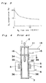
- FIG. 1 schematically shows an equipment for use in measuring the amount of the air inflow into the muffle tube.
- This equipment comprises a muffle tube 101, an inlet 102 for purging gas, a gas sampling tube 103, a device 104 for measuring an oxygen concentration and a pump 105, and additionally a zone heater (not shown) around the muffle tube 101.
- An inner diameter of the muffle tube 101 is 150 mm, and the front end of the gas sampling tube 103 is fixed at a point 1 m below from the upper edge of the muffle tube.
- the results are shown in Fig. 3. These results indicate that the air flows into the muffle tube, and such air inflow cannot be prevented by increase of the amount of purging nitrogen gas.
- the interior space of the muffle tube is contaminated by dusts in the air.
- the dusts comprise SiO2, Al2O3, Fe2O3 and the like.
- Al2O3 will cause devitrification of the preform
- Fe2O3 will cause increase of transmission loss of the optical fiber.
- the inner surface of the carbon made muffle tube is oxidized.
- tar or pitch which is used as a binder is firstly oxidized. Therefore, the remaining graphite particles are dropped or splashed and float in the furnace. Since said particles adhere to the surface of the sintered glass preform, the optical fiber fabricated from such the glass preform has many parts with low strength. As a natural consequence, the lifetime of the carbon made muffle tube is extremely shortened.
- the first measure to prevent such oxidation of the muffle tube is to reduce the temperature to 400 °C or lower at which the carbon is not oxidized during the insertion and removal of the glass preform.
- an operation rate of the furnace is greatly decreased.
- a considerable amount of oxygen and moisture in the air is adsorbed on the muffle tube since the carbon made muffle tube is porous. Then, the oxidation cannot be prevented completely.
- a method is described in PCT International Publication No. WO 88/06145. Said method comprises initially disposing the porous glass preform in a front chamber on the top of the muffle tube and inserting the glass preform into the muffle tube after gas replacement of the atmosphere in the front chamber with an inert gas.
- the muffle tube equipped with the front chamber is shown in Fig. 4.
- the carbon heater 4 and the carbon made muffle tube 3 are provided in the furnace body 5 as shown in Fig. 4.
- the heating furnace comprises an inlet 6 for introducing a purging nitrogen to the furnace body, an inlet 7 for introducing an atmosphere gas to the muffle tube, supporting rod 2 for the glass preform, the front chamber 11, an exit 14 for exhausting the gas from the front chamber and a partition 16.
- the glass preform 1 is inserted into the heating furnace.
- the removal of the glass preform from the heating furnace is carried out as follows:
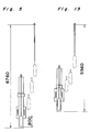
- FIG. 5 shows an example of the heating apparatus for thermal treatment of a porous glass preform having an overall length of 800 mm and a seed rod length of 200 mm.
- the length from the lower end of the muffle tube to the lower end of the chuck is 6760 mm and the overall length of the apparatus reaches nearly 8000 mm by taking account of spaces for operation and design.
- the partition 16 should be adaptable to both cases where the supporting rod is and is not extending through the partition, three members in total should be used, two of which are split members each having a partly cut off portion for the supporting rod, and one of which is a member to close an aperture through which the rod is passed.
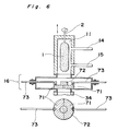
- Fig. 6 shows a cross-sectional view of the partition in detail when the glass preform 1 is disposed in the front chamber 11.
- Fig. 7 shows the glass preform 1 being inserted into the heating atmosphere of the muffle tube through the partition 16 after the atmosphere in the front chamber is replaced with an inert gas and the partition 16 is opened, and
- Fig 8 shows when the glass preform is thermally treated.
- three members that is, the covering member 72 for covering an aperture and two split members 71 which are operated with two sliding rods 73 should be used.
- a heating furnace comprising a furnace body, a cylindrical zone heater in said furnace body, a muffle tube installed through said furnace body for thermally treating a porous preform made of high purity quartz glass by moving the preform vertically therethrough; a partition means in the portion of the muffle tube projecting above the furnace body to divide an interior space of the muffle tube into an upper space and a lower one; said partition means being a single piece member; there being a member for accommodating said partition means connected to the muffle tube.
- Fig. 9 shows one example of the embodiment of the heating furnace according to the present invention.
- the heating furnace comprises a carbon heater 4 in a furnace body 5 and a muffle tube 3 through the furnace body.
- the muffle tube comprises a middle member 35 and a lower member 36 each made of high purity carbon coated with SiC or carbon, and an upper member 33 and an upper cover 37 each made of quartz.
- the porous glass preform 1 is inserted into the heating furnace comprising an inlet 6 for introducing nitrogen as a purging gas to the furnace body, an inlet 7 for introducing an atmosphere gas to the muffle tube, a supporting rod 2 for the glass preform, an outlet 21 for exhausting the atmosphere gas from the muffle tube, an inlet 22 for introducing nitrogen gas for replacement of the upper space of the muffle tube and a partition means 23 made of quartz having a small aperture 24 for passing a gas.
- the partition means 23 is arranged such that it can be opened or closed by a quartz made rod 26 from the outside.
- the aperture 24 may be omitted if the gas can flow from the lower space of the muffle tube to the upper space of the muffle tube through any narrow gap or if any outlet for exhausting the gas is provided in the muffle tube below the partition.
- partition means 23 that is, a partition means with no aperture
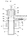
- Figs. 10 and 11 show in detail the structure of the partition means 23 and Fig. 12 which shows one embodiment of the heating furnace having such partition means.
- the partition means in Figs. 10 and 11 comprises a partition 23, an upper flange 42 which is connected to the upper member 33 of the muffle tube 3 and a lower flange 43 which is connected to the middle members 34 and 35 with lower member 36 of the muffle tube. Both the flanges sandwich the box member 41.
- the partition 23 may be opened or closed by the operating rod 26 from the outside.
- the partition 23 is guided by the rails 45 so that it does not deviate from the direction along which the partition 23 should be moved.
- the operating rod has a step so that the diameter thereof is changed in the intermediate portion of the rod.
- the tip portion 46 of the operating rod has, for example, a hook member such that the tip portion can be engaged with a projection on the edge portion of the partition.
- the engagement between the projection 47 of the partition and the tip portion 46 having the hook means can be released by rotating the rod 26. Therefore, after release, the operating rod 26 is moved back and rotated again so that a further engagement can be established between the hook means and the opposite side of the projection 47. In such a case, the step of the operating rod can be omitted.
- the partition means In order to purge the interior space of the partition means, it comprises inlets 22 for introducing the inert gas on the side surface near the upper flange 42 of the partition means and in the sliding portion 48 between the box member 41 and the sliding rod 26.
- the sliding portion 48 is arranged such that the operating rod 26 can be slid into the box member 41 and the sliding portion may be sealed by an O-ring or may be an injection syringe structure with nitrogen purging.
- the atmosphere gas is exhausted through the outlet 49 when the atmosphere gas is supplied into the middle and lower members of the muffle tube through the inlet 7 for introducing the gas.
- the difference between the embodiments shown in Figs. 9 and 10 is that the purging gas in the middle and lower members of the muffle tube is exhausted to the upper member of the muffle tube 33 in the former or through the outlet 49 for exhausting the gas in the latter while the partition is closed. Others are not substantially different between these two embodiments.
- a heater 25 can be provided. It can heat the glass preform 1 at 100 to 800 °C when the preform is present in the interior space of the muffle tube above the partition means 23. Such the heater may be a resistance heater or an infrared heating lamp. The glass preform 1 should be completely accommodated within the upper space of the muffle tube.
- the position where the partition means is located between the upper and lower spaces is not critical and also is not limited to the embodiment shown in Fig. 12 Generally, the partition means is located in the upper space above the furnace body.
- the partition means is operated as follows:
- the preform is removed from the heating furnace as follows:
- the heating apparatus comprising the heating furnace according to the present invention as shown in Fig. 9 was designed, in which a porous glass preform having the total length of 800 mm and the seed rod having the length of 200 mm can be suitably treated.
- the required minimum length for the heating apparatus from the lower end of the muffle tube to the lower end of the chuck was 5560 mm as shown in Fig. 13.
- the total length of the heating apparatus containing the length necessary for design and the length necessary for operation was 6800 mm, which was shorter by about 1.2 m than that of the apparatus as shown in Fig. 5 in which the same glass preform can be treated.
- the heating furnace as shown in Fig. 9 was used.
- the porous glass material was disposed in the upper member 33 of the muffle tube and the upper cover 37 was closed. Nitrogen gas was introduced into the upper member at the flow rate of 10 l/min. for ten minutes and also nitrogen gas was supplied into the lower and the middle members of the muffle tube at the flow rate of 10 l/min. for ten minutes. During this procedure, the partition 23 was closed.
- the muffle tube comprised the middle and the lower members 34, 35 and 36 made of high purity carbon, outer surfaces of which were coated with a gas impermeable carbon layer or a SiC layer.
- the partition 23 was opened and the glass preform was inserted in the middle and the lower members of the muffle tube and thermally treated to obtain the preform for the production of the optical fiber.
- the conditions of the dehydration and the sintering operations were as follows: Dehydration operation: He supply rate 10 l/min. Cl2 supply rate 500 cc/min. Preform traverse rate 8 mm/min. Temperature 1100 °C Sintering operation: He supply rate 10 l/min. Preform traverse rate 3 mm/min. Temperature 1650 °C
- a glass preform for the optical fiber was produced by using the obtained preform as a core material and a fluorine-doped glass pipe which was separately produced as a cladding and integrating them in a resistance heating furnace. Such the preform of which outside surface was coated with an additional glass layer to adjust the diameter thereof was drawn to produce a pure silica-core single mode optical fiber.
- the transmission loss of the optical fiber at the light wavelength of 1.55 »m was found to be as low as 0.18 dB/km.
- Example 2 The thermal treatment of the porous glass preform as in Example 2 was repeated forty times. An amount of lost carbon during the series of the treatments was 14 g, which amount corresponded to exhaustion of carbon layer of 35 »m in thickness due to oxidation in the heated portion. Such the amount indicates that the carbon made muffle tube can be used for about two years.
- the porous glass preform was disposed in the front chamber 11 and the upper cover of the chamber was closed. Nitrogen gas was introduced into the front chamber at the flow rate of 10 l/min. for ten minutes to replace the interior atmosphere of the front chamber. During this step, the partition 16 was closed. Then, the partition was opened, the porous glass preform was lowered into the muffle tube 3 and then thermally treated after closing the partition to produce a transparent glass preform for the optical fiber.
- An optical fiber was produced by using the obtained preform as the core in the same manner as in Example 1.
- the transmission loss of the optical fiber at the light wavelength of 1.55 »m was measured to be as low as 0.18 dB/km.
- the thermal treatment of the porous glass preform as in Comparative Example 1 was repeated forty times.
- An amount of lost carbon during the series of the treatments was 20 g, which amount corresponds to exhaustion of carbon layer of 50 »m in thickness due to oxidation in the heated portion. Such the amount indicates that the carbon made muffle tube can be used for about one year and a half.
- Example 2 was repeated except that period for the nitrogen replacement was increased to twenty minutes and the glass preform was heated by an infrared lamp of 800 W during the replacement. Further, in order to heat the preform uniformly, it was rotated during the replacement.
- the exhausted amount of carbon of the muffle tube was 6 g, which corresponded to exhaustion of carbon layer of 5 »m in thickness from the surface. Such the amount indicates that the carbon made muffle tube can be used for about five years.
- the effects of the present invention are as follows: The inflow of the atmosphere around the heating furnace can be prevented, whereby the contamination of the heating atmosphere in the muffle tube due to the impurities in the air may be prevented. Then, the devitrification of the glass preform can be prevented and also the transparency of the preform can be improved.
- the life of the muffle tube may be extended since the carbon loss due to oxidization is suppressed.
- the similar or the improved effects as described above may be provided by the heating furnace according to the present invention in spite of the simplicity in the structure and the mechanism of the muffle tube. Further, the total length of the heating apparatus can be shorter.
- an operating efficiency of the heating furnace is improved since the glass preform can be inserted to and removed from the muffle tube without reducing the temperature of the muffle tube.
Landscapes
- Chemical & Material Sciences (AREA)
- Engineering & Computer Science (AREA)
- Chemical Kinetics & Catalysis (AREA)
- Physics & Mathematics (AREA)
- General Chemical & Material Sciences (AREA)
- Life Sciences & Earth Sciences (AREA)
- Thermal Sciences (AREA)
- General Life Sciences & Earth Sciences (AREA)
- Geochemistry & Mineralogy (AREA)
- Manufacturing & Machinery (AREA)
- Materials Engineering (AREA)
- Organic Chemistry (AREA)
- Manufacture, Treatment Of Glass Fibers (AREA)
Claims (6)
- Four à réchauffer comprenant un corps de four (5), un dispositif de chauffage en zone cylindrique (4), disposé dans ledit corps de four, un tube formant moufle (3), installé au travers dudit corps de four pour le traitement thermique d'une ébauche poreuse (1), constituée de verre quartzeux de haute pureté, en déplaçant verticalement ladite ébauche au travers dudit tube et un moyen de partage (23) prévu dans la partie (33) du tube formant moufle (3), qui s'étend au-dessus du corps de four (5), pour séparer un espace intérieur du tube formant moufle, en un espace supérieur et un espace inférieur, caractérisé en ce que ledit moyen de partage (23) est un élément constitué par une seule pièce ; et en ce qu'un élément (41) pour loger ledit moyen de partage (23) est relié au tube formant moufle (3).
- Four à réchauffer selon la revendication 1, dans lequel un espace supérieur formé par partage, à l'aide du moyen de partage (23), a un volume qui est suffisamment grand pour loger l'ébauche en verre (1).
- Four à réchauffer selon la revendication 1, dans lequel une partie inférieure (35, 36) du tube formant moufle (3), située en dessous du moyen de partage (23) est constituée de carbone de haute pureté.
- Four à réchauffer selon la revendication 1, dans lequel une partie supérieure (33) du tube formant moufle (3), située au-dessus du moyen de partage (23) est constituée de verre quartzeux.
- Four à réchauffer selon la revendication 1, dans lequel un moyen de chauffage (25) est prévu autour d'une partie supérieure (33) du tube formant moufle, située au-dessus du moyen de partage (23).
- Four à réchauffer selon la revendication 1, dans lequel le moyen de partage (23) est constitué de verre quartzeux.
Priority Applications (1)
| Application Number | Priority Date | Filing Date | Title |
|---|---|---|---|
| DE1990610484 DE69010484T2 (de) | 1990-04-05 | 1990-04-05 | Ofen für die Herstellung einer hochreinen Quarzglasform. |
Applications Claiming Priority (2)
| Application Number | Priority Date | Filing Date | Title |
|---|---|---|---|
| JP63332005A JPH02180728A (ja) | 1988-12-29 | 1988-12-29 | 高純度石英母材製造用加熱炉 |
| JP1242689U JPH0646982Y2 (ja) | 1989-02-02 | 1989-02-02 | 高純度石英母材製造用加熱炉 |
Publications (2)
| Publication Number | Publication Date |
|---|---|
| EP0450124A1 EP0450124A1 (fr) | 1991-10-09 |
| EP0450124B1 true EP0450124B1 (fr) | 1994-07-06 |
Family
ID=26348039
Family Applications (1)
| Application Number | Title | Priority Date | Filing Date |
|---|---|---|---|
| EP90106551A Expired - Lifetime EP0450124B1 (fr) | 1988-12-29 | 1990-04-05 | Four pour la fabrication d'une préforme en quartz de haute pureté |
Country Status (5)
| Country | Link |
|---|---|
| US (1) | US5032079A (fr) |
| EP (1) | EP0450124B1 (fr) |
| KR (1) | KR920001386B1 (fr) |
| AU (1) | AU626362B2 (fr) |
| GB (1) | GB2226628B (fr) |
Families Citing this family (11)
| Publication number | Priority date | Publication date | Assignee | Title |
|---|---|---|---|---|
| AU626362B2 (en) * | 1988-12-29 | 1992-07-30 | Sumitomo Electric Industries, Ltd. | Furnace for producing high purity quartz glass preform |
| GB9210327D0 (en) * | 1992-05-14 | 1992-07-01 | Tsl Group Plc | Heat treatment facility for synthetic vitreous silica bodies |
| JP3060782B2 (ja) * | 1993-06-08 | 2000-07-10 | 住友電気工業株式会社 | 高純度透明ガラスの製造方法 |
| WO1999023040A1 (fr) * | 1997-10-31 | 1999-05-14 | Corning Incorporated | Appareil permettant l'etirage de fibres de guide d'ondes et procede correspondant |
| US5974838A (en) * | 1998-07-07 | 1999-11-02 | Alcatel | Optical fiber graphite furnace featuring an automatic shutter door system for feeding an optical preform |
| JP4615085B2 (ja) * | 2000-03-21 | 2011-01-19 | 古河電気工業株式会社 | 光ファイバ母材吊下げ支持装置 |
| DE10020033C2 (de) * | 2000-04-22 | 2003-04-03 | Heraeus Quarzglas | Vorrichtung zum Sintern eines Formkörpers |
| DE10218864C1 (de) * | 2002-04-26 | 2003-10-23 | Heraeus Tenevo Ag | Verfahren zur Herstellung eines zylinderförmigen Quarzglaskörpers mit geringem OH-Gehalt |
| CN103626381B (zh) * | 2012-08-27 | 2015-12-02 | 浙江富通光纤技术有限公司 | 一种用于烧结玻璃松散体的石墨炉 |
| CN109252218A (zh) * | 2018-11-26 | 2019-01-22 | 浙江晶阳机电有限公司 | 一种带有移动升降装置的硅芯铸锭炉 |
| CN109252217A (zh) * | 2018-11-26 | 2019-01-22 | 浙江晶阳机电有限公司 | 一种一炉多用的硅芯铸锭炉 |
Citations (2)
| Publication number | Priority date | Publication date | Assignee | Title |
|---|---|---|---|---|
| EP0405580A2 (fr) * | 1989-06-29 | 1991-01-02 | Sumitomo Electric Industries, Ltd. | Traitement thermique de préformes de fibres de verre |
| EP0416614A1 (fr) * | 1989-09-06 | 1991-03-13 | Sumitomo Electric Industries, Ltd. | Four de chauffage pour la préforme d'une fibre optique et procédé de fabrication d'une préforme de verre |
Family Cites Families (7)
| Publication number | Priority date | Publication date | Assignee | Title |
|---|---|---|---|---|
| GB332656A (en) * | 1929-05-03 | 1930-07-31 | Metallgesellschaft Ag | Process of and apparatus for bright annealing metals |
| GB843975A (en) * | 1958-01-07 | 1960-08-10 | Vickers Electrical Co Ltd | Improvements in and relating to casting in vacuum and inert gas |
| DE3440277C1 (de) * | 1984-11-03 | 1986-05-22 | Siempelkamp Gießerei GmbH & Co, 4150 Krefeld | Verfahren zum Einbringen von radioaktiven Abfaellen in einen Schmelzofen und Vorrichtung zur Durchfuehrung des Verfahrens |
| WO1988006145A1 (fr) * | 1987-02-16 | 1988-08-25 | Sumitomo Electric Industries, Ltd. | Four de chauffage pour materiaux en verre pour fibre optique et leur methode de fabrication |
| JPH01183430A (ja) * | 1988-01-14 | 1989-07-21 | Sumitomo Electric Ind Ltd | 多孔質光ファイバ母材の脱水焼結炉 |
| AU626362B2 (en) * | 1988-12-29 | 1992-07-30 | Sumitomo Electric Industries, Ltd. | Furnace for producing high purity quartz glass preform |
| JPH02196045A (ja) * | 1989-01-23 | 1990-08-02 | Sumitomo Electric Ind Ltd | 高純度石英母材製造用加熱炉 |
-
1989
- 1989-12-19 AU AU46870/89A patent/AU626362B2/en not_active Ceased
- 1989-12-20 GB GB8928691A patent/GB2226628B/en not_active Expired - Fee Related
- 1989-12-29 KR KR898920189A patent/KR920001386B1/ko not_active Expired
- 1989-12-29 US US07/459,299 patent/US5032079A/en not_active Expired - Lifetime
-
1990
- 1990-04-05 EP EP90106551A patent/EP0450124B1/fr not_active Expired - Lifetime
Patent Citations (2)
| Publication number | Priority date | Publication date | Assignee | Title |
|---|---|---|---|---|
| EP0405580A2 (fr) * | 1989-06-29 | 1991-01-02 | Sumitomo Electric Industries, Ltd. | Traitement thermique de préformes de fibres de verre |
| EP0416614A1 (fr) * | 1989-09-06 | 1991-03-13 | Sumitomo Electric Industries, Ltd. | Four de chauffage pour la préforme d'une fibre optique et procédé de fabrication d'une préforme de verre |
Also Published As
| Publication number | Publication date |
|---|---|
| KR920001386B1 (en) | 1992-02-13 |
| US5032079A (en) | 1991-07-16 |
| GB8928691D0 (en) | 1990-02-28 |
| EP0450124A1 (fr) | 1991-10-09 |
| AU626362B2 (en) | 1992-07-30 |
| AU4687089A (en) | 1990-07-05 |
| GB2226628B (en) | 1993-05-26 |
| GB2226628A (en) | 1990-07-04 |
Similar Documents
| Publication | Publication Date | Title |
|---|---|---|
| EP0450124B1 (fr) | Four pour la fabrication d'une préforme en quartz de haute pureté | |
| EP0542724B1 (fr) | Four pour le chauffage d'une préforme en verre et procédé de fabrication d'une préforme en verre | |
| EP0380054B1 (fr) | Four pour le chauffage de préformes à quartz pour fibres optiques | |
| US5259856A (en) | Method of producing glass preform in furnace for heating glass | |
| US5470369A (en) | Process for consolidation of porous preform for optical fiber | |
| EP0529694B1 (fr) | Procédé de traitement thermique d'une préforme pour fibre optique | |
| US6497118B1 (en) | Method and apparatus for reducing refractory contamination in fused silica processes | |
| KR900004381B1 (ko) | 유리 광섬유의 제조방법 | |
| KR0141593B1 (ko) | 광섬유의 유리예비성형물의 가열용광로와 유리예비성형물의 제조방법 | |
| EP0302121B1 (fr) | Four de chauffage pour materiaux en verre pour fibre optique et leur methode de fabrication | |
| JPS5858299B2 (ja) | 低損失光ファイバ用多孔質母材の脱水焼結方法 | |
| CA2013730A1 (fr) | Four pour fabriquer des preformes de verre de quartz pur | |
| US20110100064A1 (en) | Method and apparatus for manufacturing an optical fiber core rod | |
| JPH0646982Y2 (ja) | 高純度石英母材製造用加熱炉 | |
| KR20030094037A (ko) | 저손실 광섬유 모재 및 그 제조 방법 | |
| JPH0442339B2 (fr) | ||
| CA1323193C (fr) | Four servant au chauffage d'ebauches en verre pour la production de fibres optiques et mode de production desdites ebauches | |
| CA2013731A1 (fr) | Four de chauffage de preformes de quartz de grande purete pour la fabrication des fibres optiques | |
| EP0520422A2 (fr) | Procédé de fabrication d'un objet en verre | |
| JP2003226541A (ja) | ガラス母材の製造方法及び製造装置 | |
| JP2007284302A (ja) | 低損失光ファイバ母材の製造方法 | |
| JPH03146434A (ja) | 高純度石英多孔質ガラス母材の加熱処理方法およびそのための加熱炉 |
Legal Events
| Date | Code | Title | Description |
|---|---|---|---|
| PUAI | Public reference made under article 153(3) epc to a published international application that has entered the european phase |
Free format text: ORIGINAL CODE: 0009012 |
|
| 17P | Request for examination filed |
Effective date: 19901220 |
|
| AK | Designated contracting states |
Kind code of ref document: A1 Designated state(s): DE FR IT |
|
| 17Q | First examination report despatched |
Effective date: 19920122 |
|
| GRAA | (expected) grant |
Free format text: ORIGINAL CODE: 0009210 |
|
| AK | Designated contracting states |
Kind code of ref document: B1 Designated state(s): DE FR IT |
|
| ITF | It: translation for a ep patent filed | ||
| REF | Corresponds to: |
Ref document number: 69010484 Country of ref document: DE Date of ref document: 19940811 |
|
| ET | Fr: translation filed | ||
| PLBE | No opposition filed within time limit |
Free format text: ORIGINAL CODE: 0009261 |
|
| STAA | Information on the status of an ep patent application or granted ep patent |
Free format text: STATUS: NO OPPOSITION FILED WITHIN TIME LIMIT |
|
| 26N | No opposition filed | ||
| PGFP | Annual fee paid to national office [announced via postgrant information from national office to epo] |
Ref country code: FR Payment date: 19970409 Year of fee payment: 8 |
|
| PGFP | Annual fee paid to national office [announced via postgrant information from national office to epo] |
Ref country code: DE Payment date: 19970414 Year of fee payment: 8 |
|
| PG25 | Lapsed in a contracting state [announced via postgrant information from national office to epo] |
Ref country code: FR Free format text: THE PATENT HAS BEEN ANNULLED BY A DECISION OF A NATIONAL AUTHORITY Effective date: 19980430 |
|
| PG25 | Lapsed in a contracting state [announced via postgrant information from national office to epo] |
Ref country code: DE Free format text: LAPSE BECAUSE OF NON-PAYMENT OF DUE FEES Effective date: 19990202 |
|
| REG | Reference to a national code |
Ref country code: FR Ref legal event code: ST |
|
| PG25 | Lapsed in a contracting state [announced via postgrant information from national office to epo] |
Ref country code: IT Free format text: LAPSE BECAUSE OF NON-PAYMENT OF DUE FEES;WARNING: LAPSES OF ITALIAN PATENTS WITH EFFECTIVE DATE BEFORE 2007 MAY HAVE OCCURRED AT ANY TIME BEFORE 2007. THE CORRECT EFFECTIVE DATE MAY BE DIFFERENT FROM THE ONE RECORDED. Effective date: 20050405 |