EP0450131A1 - Appareil de radiation à micro-ondes sans électrodes - Google Patents
Appareil de radiation à micro-ondes sans électrodes Download PDFInfo
- Publication number
- EP0450131A1 EP0450131A1 EP90106671A EP90106671A EP0450131A1 EP 0450131 A1 EP0450131 A1 EP 0450131A1 EP 90106671 A EP90106671 A EP 90106671A EP 90106671 A EP90106671 A EP 90106671A EP 0450131 A1 EP0450131 A1 EP 0450131A1
- Authority
- EP
- European Patent Office
- Prior art keywords
- lamp
- microwave
- radiation
- microwave cavity
- cavity
- Prior art date
- Legal status (The legal status is an assumption and is not a legal conclusion. Google has not performed a legal analysis and makes no representation as to the accuracy of the status listed.)
- Granted
Links
Images


Classifications
-
- H—ELECTRICITY
- H01—ELECTRIC ELEMENTS
- H01J—ELECTRIC DISCHARGE TUBES OR DISCHARGE LAMPS
- H01J65/00—Lamps without any electrode inside the vessel; Lamps with at least one main electrode outside the vessel
- H01J65/04—Lamps in which a gas filling is excited to luminesce by an external electromagnetic field or by external corpuscular radiation, e.g. for indicating plasma display panels
- H01J65/042—Lamps in which a gas filling is excited to luminesce by an external electromagnetic field or by external corpuscular radiation, e.g. for indicating plasma display panels by an external electromagnetic field
- H01J65/044—Lamps in which a gas filling is excited to luminesce by an external electromagnetic field or by external corpuscular radiation, e.g. for indicating plasma display panels by an external electromagnetic field the field being produced by a separate microwave unit
Definitions
- the present invention relates to an electrodeless microwave-generated radiation apparatus for exciting a lamp containing emission material such as mercury by the use of microwave energy to emit radiation in the ultraviolet portion of the spectrum.
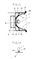
- FIG. 8b is a sectional view taken along the line B-B of Fig. 8a.
- a lamp 1 a microwave cavity 2
- a reflector 3 made of metal material to define the microwave cavity and having a concave or elliptical shape in cross section for converging emitted radiations in a radiating direction
- slots 4 as coupler means for supplying microwaves generated by magnetrons 5 (microwave generators) to the microwave cavity 2 via waveguides 6.
- a mesh 7 defining a wall of the microwave cavity 2 for transmitting emitted ultraviolet radiation.
- the mesh 7 acts as a short-circuit plate for microwaves while it acts as a transmitting medium for light.
- Numeral 8 is a blower for controlling the heat generated by electrical discharge, and more particularly for cooling down both lamp 1 and reflector 3 with air flow through vent-holes 9 provided in the reflector 3.
- Numeral 10 is an ultraviolet radiation bulb which serves as a source of ultraviolet radiation for initial ionization in order to trigger the formation of plasma in the lamp 1 when microwaves are introduced into the microwave cavity 2.
- microwave energy excite emission material such as mercury vapor contained in the lamp 1.
- Ultraviolet radiation from the ultraviolet radiation bulb 10 triggers electrical discharge in the lamp 1 to emit ultraviolet radiation.
- the lamp 1 is located at a focal point of the elliptically surfaced reflector 3 and thus, while a portion of the radiations emitted in all directions is directly transmitted through the mesh 7, the remaining radiations emitted in the opposite direction (upward direction) and lateral direction are reflected on the reflector 3 and advance towards the mesh 7. Therefore, an object to be processed will instantly be processed (e.g. dried and cured) when disposed beneath the mesh 7. A large number of objects can be processed continuously if they are moved successively by a belt conveyor or the like.
- mercury which is likely to emit ultraviolet radiation is contained in the lamp 1 since the apparatus aims at processing objects by ultraviolet radiation.
- the generation of visible radiation and infrared radiation besides ultraviolet radiation is, however, inevitable so that the temperature of the lamp 1 under operation becomes considerably high.
- air is supplied inside the microwave cavity 2 by the blower 8 through the vent-holes 9 provided in the reflector 3 to cool the lamp 1.
- microwaves supplied into the microwave cavity 2 are repeatedly reflected in the microwave cavity 2 at random and not properly converged on the lamp 1, so that it takes more than several tens seconds till emission of ultraviolet radiation becomes stable.
- the conventional apparatus has a drawback that harmful ozone gas generates or reflected microwave damages the magnetron till emission of ultraviolet radiation becomes stable.
- objects to be processed are overheated due to infrared radiation or visible radiation.
- the present invention was made to solve the above drawbacks, and it is an object of the present invention to provide an electrodeless radiation apparatus which can effectively couple microwave energy to a lamp so that the time required for stabilization of the emission of ultraviolet radiation is shortened, and which can reduce undesirable radiation such as infrared radiation.
- a cavity wall defining a microwave cavity and a reflector reflecting radiation are made of other material from each other, and reflector comprises a mirror made of dielectric materials which reflects ultraviolet radiation while transmitting infrared radiation. Further, heat absorbing coating for absorbing infrared radiation and a part of visible radiation is applied to the inner surface of the cavity wall as occasion demands, whereby reducing heat radiation toward objects to be processed to the utmost.
- Another means of the present invention is that, in the above electrodeless microwave-generated radiation apparatus wherein a microwave cavity wall and a reflector are made of other material from each other, the microwave cavity wall along a longitudinal direction of a lamp is protruded toward the lamp to form a convex portion.
- a further means of the present invention is a microwave-coupling means comprising a couple of antennas arranged on both sides of and parallel to the lamp, each of which antennas is coupled at one end to a coaxial converter in the waveguide and at the other end to the waveguide or microwave cavity wall.
- a still further means of the present invention is, in the electrodeless microwave-generated radiation apparatus having the microwave-coupling mean, a projection or parasitic element provided on the inner wall of the microwave cavity adjacent to the center of the lamp in order to prevent decrease in emission of ultraviolet radiation at the central area of the lamp.
- Another means of the present invention is a means for controlling flow of cooling air on detecting temperature of the glass surface of the lamp with an infrared radiation thermal sensor so that the rise time of the lamp can be minimized.
- microwave energy can be coupled to the lamp with high efficiency so that the lamp begins to emit ultraviolet radiation in a short period of time.
- the undesirable radiation such as infrated radiation can be reduced to a minimum, thus allowing desirable ultraviolet radiation to be irradiated on an object to be processed.
- microwave energy generated by a microwave generator (not shown) is supplied to a microwave cavity 2 through a waveguide 6 to make emission materials in a lamp 1 discharge and emit ultraviolet radiation.
- a microwave generator not shown
- ultraviolet radiation produced is irradiated through a mesh 7 partly defining the microwave cavity to objects to be processed.
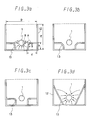
- a first feature of the embodiment is that a microwave cavity wall is structurally separated from a reflector, and that the reflector comprises a dielectric mirror 11 while the microwave cavity wall comprises a part of a housing, a cavity wall 13 made of metal sheet or plate inside the housing, and a mesh 7.
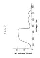
- the dielectric mirror 11 comprises a pair of symmetrical mirrors joined at center to each other.
- Each mirror comprises, for example, Fused Silica glass or Bolosilicate glass available from CORNING GLASS WORKS under the commercial name "Pyrex" of 2 mm in thickness whereon deposition films made of dielectric material such as metal oxide are formed in several or several tens layers.
- the dielectric mirror 11 can reflect desirable ultraviolet radiation while transmitting infrared or visible radiation as shown in Fig. 2 in which the relationship between reflectance and wavelength of radiation is illustrated.
- a cavity wall 13 is so formed as to protrude toward the lamp 1 as shown in Fig. 1c.
- Such shape enables the concentration of an electric field on the lamp whereby shortening rise time of emission. That is, electric lines of force are concentrated on a convex portion A (folded portion) of the cavity wall 13 as shown in Fig. 3a, so that the density of electric lines of force on the portion B of the lamp 1 facing the convex portion A is raised and electric field on the portion B is enhanced. Accordingly, excitation of plasma is intensively encouraged as compared with a known microwave cavity wall which serves as a housing or a planar microwave wall as shown in Fig. 3d.
- the dimension e of the cavity wall 13 might be so designed as to be approximately equal to the level of the central axis of the lamp 1.
- the dimensions e , d and ⁇ have relation to the dimensions D and E of the housing 12, the location or diameter of the lamp 1, and the shape of the dielectric mirror 11, and accordingly can be determined through experiments.
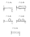
- the convex portion of the cavity wall 13 is not limited to an edged form and might be shaped as shown in Figs. 3b and 3c.
- a second feature of the embodiment is that a microwave-coupling means for feeding microwaves from waveguides 6 into the microwave cavity 2 comprises a wave-shaped antenna 17 closely disposed on both sides of and parallel to the lamp 1.
- One end of the antenna 17 is connected to the end of a coaxial converter 14 while the other end thereof is connected to the housing 12.
- the coaxial converter 14 is located within the waveguide 6 by means of a screw 15 and extends into the microwave cavity 2 through a coupler opening 16 provided on the housing 12.
- One end of the antenna 17 is connected to an end of the extended coaxial converter 14.
- the antenna 17 enables the concentration of electric field of microwave in the lamp 1, whereby promoting electrical discharging and emission of emission material contained in the lamp 1.
- the antenna 17 has a wave-shaped configuration to increase the surface area and to make microwave electric field be coupled into the lamp 1 as much as possible.
- the antenna 17 might be formed into a plate-like shape or other shapes shown in Fig. 4.
- a third feature of the present embodiment is that a projection 18 is attached by screws 19 to the housing 12 beneath the center of the lamp 1 as shown in Fig. 1d.
- the emission is sometimes weak near central portion of the lamp 1 while it is strong at both ends of the lamp 1 due to relatively strong electric field by the antenna 17.
- the projection 18 serves to carry out uniform discharging and emission in the lamp 1.
- the projection in the present invention is not limited to one shown in Fig.1d, and any means is employable so long as it can effectively concentrate electric field on the lamp 1.
- a projection of another shape shown in Fig.5a, Fig.5b, or Fig.5c, in which a corner portion is rounded off to prevent excessive convergence of electric lines of force might be employed.
- one or two parasitic elements disposed on one or both sides of the lamp 1 as shown in Fig. 5d, Fig. 5e, Fig. 5f or Fig. 5g might be employed.
- the parasitic element acts as a waveguide like an auxiliary antenna in an aerial system when the longitudinal length of the parasitic element is designed to be ⁇ /2 ( ⁇ : wavelength of microwaves in free space), and contributes to intensifying the emission at the central area.
- a parasitic element having such shape as shown in Fig.5e, Fig.5f or Fig.5g provides an desirable length within a limited range.
- Fig. 6a and 6b The relationship between relative energy of ultraviolet radiation and the location on the lamp (total length: 250 mm) in the longitudinal direction is shown in Fig. 6a and 6b in order to compare the intensity of emission at the central area of the lamp when providing a projection portion (Fig. 6b) to that when not providing a projection portion (Fig. 6a).
- Fig. 6a shows that the relative energy of ultraviolet radiation at center reduces to 76 % of that at both ends
- Fig. 6b shows that the relative energy of ultraviolet radiation at center is 1.4 times higher than that at both ends.
- the intensity of emission varies depending on location of the projection, clearance between the projection and the lamp, and the like, so that the intensity of emission at the central area can be made higher than or equal to that at both ends.
- a fourth feature of the present embodiment is that an infrared radiation thermal sensor 20 is provided adjacent to the lamp 1 but outside the microwave cavity 2, in order to shorten the rise time of emission by decreasing air flow from the blower 8 when the temperature of the lamp 1 is low before emission.
- the lamp 1 is cooled down with air from the blower 8 through vent-holes 21, 22, 23 and 24 provided on the dielectric mirror 11, the housing 12, the cavity wall 13, and the projection 18 respectively to prevent damage of the lamp 1 caused by overheat during emission. If the lamp 1 before the start of emission is cooled down with air like the lamp which is emitting, the temperature of the lamp 1 remains low due to overcooling so that the start of emission is delayed.
- Fig. 7a to 7d show relationship between supply time of microwave energy and temperature of the lamp 1 or relative energy of ultraviolet radiation produced. More particularly, Figs. 7a and 7c show relationship between supply time of microwave energy and temperature of the lamp surface (Fig. 7a) or relative energy of ultraviolet radiation (Fig. 7c) in which air flow from the blower is constant from the start of microwave energy supply, and Figs. 7b and 7d show relationship between supply time of microwave energy and temperature of the lamp surface (Fig. 7b) or relative energy of ultraviolet radiation (Fig. 7d) in which air flow from the blower is so controlled as to be half of the usual air flow till the temperature of the lamp 1 rises to 500°C as shown in Fig. 7e. As is clear from Figs. 7a to 7d, it takes about twelve seconds to emit sufficient amount of ultraviolet radiation when air flow is not controlled, while such rise time can be shortened to about eight seconds by controlling air flow.
- the use of the infrared radiation thermal sensor 20 detecting wavelength of not less than 3 ⁇ m can avoid the influence of plasma and ultraviolet radiation in the lamp 1, so that the temperature of the glass surface of the lamp 1 can be accurately detected.
- the infrared radiation thermal sensor 20 might be made of InSb.
- the air flow can be controlled by varying the direction of a air-flow-variable plate mounted on the blower 8 by means of a motor driven by a signal from the infrared radiation thermal sensor 20 through a control circuit.
- the microwave cavity and the reflector wall are made of other materials from each other, so that the reflector wall can be made of specific material to form a dielectric mirror as started above, whereby enabling reflection of desirable ultraviolet radiation while enabling transmission of undesirable infrared radiation and visible radiation. Accordingly, if heat-absorbing coating is applied to an inner wall of the cavity wall 13 or housing 12 behind the dielectric mirror 11, the temperature up of objects to be processed can be avoided since the inner wall absorbs transmitted heat rays without reflecting the same, so that ultraviolet radiation curing of the objects to be processed, a temperature of which should not be rised, can be preferably carried out.
- the mesh 7 defining a part of the microwave cavity is connected to the housing 12 by means of a screw 26 attached to the housing 12 and a tapping plate 27, and the dielectric mirror 11 is fixed to a supporting means 28 attached to the housing 12.
- the connecting or fixing method is not limited in the present invention, and other method can be employable.
- a wall defining a microwave cavity can be integrated with a housing, i.e. the microwave cavity can be defined by a part of the housing, though a microwave cavity wall 13 is attached to the inner wall of the housing 12 in the above embodiment.
- the time from the start of supply of microwave energy to the start of discharging and emission of the lamp can be remarkably shortened. That is, the rise time of thirty seconds in the case of conventional apparatus can be shortened to about five or six seconds by employing the above-mentioned several means. In result, the influence of reflected microwave energy on a magnetron can be significantly reduced whereby lengthening life time of the magnetron. That is, in the conventional apparatus, microwave energy supplied into the microwave cavity is not effectively used and reflected to a magnetron (microwave generator) till the discharging in the lamp starts to emit ultraviolet radiation, whereby giving undesirable influence on the life time of the magnetron. On the contrary, the rise time is remarkably shortened so that the harm caused by the reflected microwave energy can be reduced in the apparatus of the present invention.
- the intensity of emission along an axial direction of the bar-shaped lamp can be controlled by a projection or parasitic element, so that the intensity of emission at the central area can be so controlled as to be equal to, or higher or lower than that at both ends of the lamp depending on the nature of objects to be processed.
- a dielectric mirror which can reflect only ultraviolet radiation while transmitting visible radiation and infrared radiation, is employable so that the apparatus gives a great effect in treating objects with ultraviolet radiation without rising the temperature of the objects too high.
Landscapes
- Physics & Mathematics (AREA)
- Electromagnetism (AREA)
- Engineering & Computer Science (AREA)
- Plasma & Fusion (AREA)
- Discharge Lamps And Accessories Thereof (AREA)
- Physical Or Chemical Processes And Apparatus (AREA)
- Constitution Of High-Frequency Heating (AREA)
Priority Applications (3)
| Application Number | Priority Date | Filing Date | Title |
|---|---|---|---|
| EP90106671A EP0450131B1 (fr) | 1990-04-06 | 1990-04-06 | Appareil de radiation à micro-ondes sans électrodes |
| US07/505,748 US5039918A (en) | 1990-04-06 | 1990-04-06 | Electrodeless microwave-generated radiation apparatus |
| DE69021371T DE69021371T2 (de) | 1990-04-06 | 1990-04-06 | Elektrodenloses, durch Mikrowellen erregtes Strahlungsgerät. |
Applications Claiming Priority (1)
| Application Number | Priority Date | Filing Date | Title |
|---|---|---|---|
| EP90106671A EP0450131B1 (fr) | 1990-04-06 | 1990-04-06 | Appareil de radiation à micro-ondes sans électrodes |
Publications (2)
| Publication Number | Publication Date |
|---|---|
| EP0450131A1 true EP0450131A1 (fr) | 1991-10-09 |
| EP0450131B1 EP0450131B1 (fr) | 1995-08-02 |
Family
ID=8203867
Family Applications (1)
| Application Number | Title | Priority Date | Filing Date |
|---|---|---|---|
| EP90106671A Expired - Lifetime EP0450131B1 (fr) | 1990-04-06 | 1990-04-06 | Appareil de radiation à micro-ondes sans électrodes |
Country Status (3)
| Country | Link |
|---|---|
| US (1) | US5039918A (fr) |
| EP (1) | EP0450131B1 (fr) |
| DE (1) | DE69021371T2 (fr) |
Cited By (9)
| Publication number | Priority date | Publication date | Assignee | Title |
|---|---|---|---|---|
| EP0604935A1 (fr) * | 1992-12-31 | 1994-07-06 | Gte Products Corporation | Structure de couplage à puissance équilibrée pour une lampe à décharge sans électrodes |
| EP0819317A4 (fr) * | 1995-03-09 | 1998-06-17 | Fusion Lighting Inc | Appareil d'excitation d'une lampe sans electrode par un rayonnement hyperfrequence |
| DE4400199C2 (de) * | 1993-01-13 | 2003-04-17 | Fusion Lighting Inc | Mikrowellengespeiste Lampe |
| EP1513218A1 (fr) * | 2003-09-08 | 2005-03-09 | Lg Electronics Inc. | Résonateur dans un système d' éclairage sans électrodes |
| EP1259100A3 (fr) * | 2001-05-17 | 2005-05-04 | JenAct Limited | Dispositif de commande de sources lumineuses alimentées par micro-ondes |
| EP1134775A3 (fr) * | 2000-01-18 | 2005-11-09 | Ushiodenki Kabushiki Kaisha | Ensemble projecteur excité par énergie électromagnétique |
| EP1519408A3 (fr) * | 2003-09-03 | 2006-03-08 | Lg Electronics Inc. | Système d' éclairage sans électrodes |
| EP1879215A3 (fr) * | 2006-07-12 | 2008-01-23 | Nordson Corporation | Système de lampe à rayonnement ultraviolet doté d'un contrôle d'air de refroidissement |
| WO2010106332A1 (fr) * | 2009-03-19 | 2010-09-23 | Gew (Ec) Limited | Boîtier amélioré pour appareil de séchage d'encre |
Families Citing this family (21)
| Publication number | Priority date | Publication date | Assignee | Title |
|---|---|---|---|---|
| US5223822A (en) * | 1992-04-24 | 1993-06-29 | Stonel Corporation | Valve position indicator |
| US5370247A (en) * | 1993-08-05 | 1994-12-06 | Ford Motor Company | Ferris wheel type container positioning mechanism |
| US5448135A (en) * | 1993-10-28 | 1995-09-05 | Fusion Lighting, Inc. | Apparatus for coupling electromagnetic radiation from a waveguide to an electrodeless lamp |
| JP3663223B2 (ja) * | 1993-12-10 | 2005-06-22 | ゼネラル・エレクトリック・カンパニイ | 無電極放電ランプ用光結合装置及び光分配装置 |
| US5914564A (en) * | 1994-04-07 | 1999-06-22 | The Regents Of The University Of California | RF driven sulfur lamp having driving electrodes which face each other |
| US5689364A (en) * | 1995-01-06 | 1997-11-18 | W.L. Gore & Associates, Inc. | Light reflectant surface for photoinduction chambers |
| US5841233A (en) * | 1996-01-26 | 1998-11-24 | Fusion Lighting, Inc. | Method and apparatus for mounting a dichroic mirror in a microwave powered lamp assembly using deformable tabs |
| US5931557A (en) * | 1996-04-02 | 1999-08-03 | Danilychev; Vladimir A. | Energy efficient ultraviolet visible light source |
| US5666640A (en) * | 1996-04-02 | 1997-09-09 | Daniylchev; Vladimir A. | Microwave powered ozone producing system |
| JPH10321039A (ja) * | 1997-05-15 | 1998-12-04 | Matsushita Electron Corp | マイクロ波放電ランプ装置 |
| US7462978B1 (en) | 1999-09-20 | 2008-12-09 | Nordson Corporation | Apparatus and method for generating ultraviolet radiation |
| JP2002150805A (ja) * | 2000-11-14 | 2002-05-24 | Orc Mfg Co Ltd | 無電極ランプ装置 |
| US20020079796A1 (en) * | 2000-12-22 | 2002-06-27 | Okamitsu Jeffrey K. | Wavelength selective optical reflector with integral light trap |
| US6509697B2 (en) * | 2001-01-30 | 2003-01-21 | Fusion Uv Systems, Inc. | Compact microwave-powered lamp, inkjet printer using this lamp, and ultraviolet light curing using this lamp |
| JP2002337612A (ja) * | 2001-05-15 | 2002-11-27 | Murakami Corp | アンテナ内蔵ルームミラー |
| US6908586B2 (en) * | 2001-06-27 | 2005-06-21 | Fusion Uv Systems, Inc. | Free radical polymerization method having reduced premature termination, apparatus for performing the method and product formed thereby |
| US6939397B2 (en) * | 2003-05-08 | 2005-09-06 | Eco-Rx, Inc. | System for purifying and removing contaminants from gaseous fluids |
| US7564190B2 (en) * | 2006-06-09 | 2009-07-21 | Victor Company Of Japan, Ltd. | Light source device and image displaying apparatus using the same |
| US20100096569A1 (en) * | 2008-10-21 | 2010-04-22 | Applied Materials, Inc. | Ultraviolet-transmitting microwave reflector comprising a micromesh screen |
| DE102009018840A1 (de) * | 2009-04-28 | 2010-11-25 | Auer Lighting Gmbh | Plasmalampe |
| US9502149B2 (en) | 2014-08-11 | 2016-11-22 | Nordson Corporation | Ultraviolet systems and methods for irradiating a substrate |
Citations (3)
| Publication number | Priority date | Publication date | Assignee | Title |
|---|---|---|---|---|
| GB1371098A (en) * | 1971-09-29 | 1974-10-23 | Emi Ltd | Electrodeless discharge tube arrangements |
| US4504768A (en) * | 1982-06-30 | 1985-03-12 | Fusion Systems Corporation | Electrodeless lamp using a single magnetron and improved lamp envelope therefor |
| US4532427A (en) * | 1982-03-29 | 1985-07-30 | Fusion Systems Corp. | Method and apparatus for performing deep UV photolithography |
Family Cites Families (9)
| Publication number | Priority date | Publication date | Assignee | Title |
|---|---|---|---|---|
| US3911318A (en) * | 1972-03-29 | 1975-10-07 | Fusion Systems Corp | Method and apparatus for generating electromagnetic radiation |
| US3872349A (en) * | 1973-03-29 | 1975-03-18 | Fusion Systems Corp | Apparatus and method for generating radiation |
| US3987331A (en) * | 1975-03-24 | 1976-10-19 | Gte Sylvania Incorporated | Ultraviolet emitting fluorescent lamp having internal reflector film |
| US4042850A (en) * | 1976-03-17 | 1977-08-16 | Fusion Systems Corporation | Microwave generated radiation apparatus |
| US4041352A (en) * | 1976-07-14 | 1977-08-09 | Gte Laboratories Incorporated | Automatic starting system for solid state powered electrodeless lamps |
| US4359668A (en) * | 1979-03-14 | 1982-11-16 | Fusion Systems Corporation | Method and apparatus for igniting electrodeless discharge lamp |
| US4431947A (en) * | 1982-06-04 | 1984-02-14 | The Singer Company | Controlled light source |
| US4633140A (en) * | 1984-12-24 | 1986-12-30 | Fusion Systems Corporation | Electrodeless lamp having staggered turn-on of microwave sources |
| JPH0621167Y2 (ja) * | 1987-08-07 | 1994-06-01 | 高橋 柾弘 | マイクロ波励起による紫外線発生装置 |
-
1990
- 1990-04-06 EP EP90106671A patent/EP0450131B1/fr not_active Expired - Lifetime
- 1990-04-06 US US07/505,748 patent/US5039918A/en not_active Expired - Lifetime
- 1990-04-06 DE DE69021371T patent/DE69021371T2/de not_active Expired - Lifetime
Patent Citations (3)
| Publication number | Priority date | Publication date | Assignee | Title |
|---|---|---|---|---|
| GB1371098A (en) * | 1971-09-29 | 1974-10-23 | Emi Ltd | Electrodeless discharge tube arrangements |
| US4532427A (en) * | 1982-03-29 | 1985-07-30 | Fusion Systems Corp. | Method and apparatus for performing deep UV photolithography |
| US4504768A (en) * | 1982-06-30 | 1985-03-12 | Fusion Systems Corporation | Electrodeless lamp using a single magnetron and improved lamp envelope therefor |
Non-Patent Citations (1)
| Title |
|---|
| JOURNAL OF THE ILLUMINATING ENGINEERING SOCIETY, vol. 14, no. 1, October 1984, NEW YORK, US; pages 283 - 297; (KENJI YOSHIZAWA): "New light source using microwave discharge" * |
Cited By (11)
| Publication number | Priority date | Publication date | Assignee | Title |
|---|---|---|---|---|
| EP0604935A1 (fr) * | 1992-12-31 | 1994-07-06 | Gte Products Corporation | Structure de couplage à puissance équilibrée pour une lampe à décharge sans électrodes |
| DE4400199C2 (de) * | 1993-01-13 | 2003-04-17 | Fusion Lighting Inc | Mikrowellengespeiste Lampe |
| EP0819317A4 (fr) * | 1995-03-09 | 1998-06-17 | Fusion Lighting Inc | Appareil d'excitation d'une lampe sans electrode par un rayonnement hyperfrequence |
| EP1134775A3 (fr) * | 2000-01-18 | 2005-11-09 | Ushiodenki Kabushiki Kaisha | Ensemble projecteur excité par énergie électromagnétique |
| EP1259100A3 (fr) * | 2001-05-17 | 2005-05-04 | JenAct Limited | Dispositif de commande de sources lumineuses alimentées par micro-ondes |
| EP1519408A3 (fr) * | 2003-09-03 | 2006-03-08 | Lg Electronics Inc. | Système d' éclairage sans électrodes |
| CN100356504C (zh) * | 2003-09-03 | 2007-12-19 | Lg电子株式会社 | 无电极照明系统 |
| EP1513218A1 (fr) * | 2003-09-08 | 2005-03-09 | Lg Electronics Inc. | Résonateur dans un système d' éclairage sans électrodes |
| EP1879215A3 (fr) * | 2006-07-12 | 2008-01-23 | Nordson Corporation | Système de lampe à rayonnement ultraviolet doté d'un contrôle d'air de refroidissement |
| US8410410B2 (en) | 2006-07-12 | 2013-04-02 | Nordson Corporation | Ultraviolet lamp system with cooling air control |
| WO2010106332A1 (fr) * | 2009-03-19 | 2010-09-23 | Gew (Ec) Limited | Boîtier amélioré pour appareil de séchage d'encre |
Also Published As
| Publication number | Publication date |
|---|---|
| US5039918A (en) | 1991-08-13 |
| DE69021371T2 (de) | 1996-02-08 |
| DE69021371D1 (de) | 1995-09-07 |
| EP0450131B1 (fr) | 1995-08-02 |
Similar Documents
| Publication | Publication Date | Title |
|---|---|---|
| EP0450131B1 (fr) | Appareil de radiation à micro-ondes sans électrodes | |
| US6323601B1 (en) | Reflector for an ultraviolet lamp system | |
| US4504768A (en) | Electrodeless lamp using a single magnetron and improved lamp envelope therefor | |
| US4673846A (en) | Microwave discharge light source apparatus | |
| US7362055B2 (en) | Plasma lamp with dielectric waveguide | |
| US4633140A (en) | Electrodeless lamp having staggered turn-on of microwave sources | |
| US4042850A (en) | Microwave generated radiation apparatus | |
| JP2001085152A (ja) | メッシュ部材を包含するマイクロ波装置 | |
| EP1262091A1 (fr) | Lampe pourvue d'une source lumineuse au plasma, a confinement automatique | |
| US7447249B2 (en) | Lighting system | |
| KR100430012B1 (ko) | 무전극 램프의 열변형 방지장치 | |
| KR900000359B1 (ko) | 마이크로파 방전광원장치 | |
| JP2008053014A (ja) | 光照射装置 | |
| KR100556781B1 (ko) | 플라즈마 램프 시스템의 전구 | |
| JPS6340802Y2 (fr) | ||
| JPH0527946B2 (fr) | ||
| US20020079796A1 (en) | Wavelength selective optical reflector with integral light trap | |
| JPS61179055A (ja) | マイクロ波放電光源装置 | |
| KR20000050828A (ko) | 마이크로파 방전광원 장치 | |
| JPH05225961A (ja) | マイクロ波無電極発光装置 | |
| JPS6350839B2 (fr) | ||
| JPH023266B2 (fr) |
Legal Events
| Date | Code | Title | Description |
|---|---|---|---|
| PUAI | Public reference made under article 153(3) epc to a published international application that has entered the european phase |
Free format text: ORIGINAL CODE: 0009012 |
|
| 17P | Request for examination filed |
Effective date: 19910223 |
|
| AK | Designated contracting states |
Kind code of ref document: A1 Designated state(s): DE FR GB |
|
| 17Q | First examination report despatched |
Effective date: 19940127 |
|
| GRAA | (expected) grant |
Free format text: ORIGINAL CODE: 0009210 |
|
| AK | Designated contracting states |
Kind code of ref document: B1 Designated state(s): DE FR GB |
|
| REF | Corresponds to: |
Ref document number: 69021371 Country of ref document: DE Date of ref document: 19950907 |
|
| ET | Fr: translation filed | ||
| PLBE | No opposition filed within time limit |
Free format text: ORIGINAL CODE: 0009261 |
|
| STAA | Information on the status of an ep patent application or granted ep patent |
Free format text: STATUS: NO OPPOSITION FILED WITHIN TIME LIMIT |
|
| 26N | No opposition filed | ||
| REG | Reference to a national code |
Ref country code: GB Ref legal event code: IF02 |
|
| PGFP | Annual fee paid to national office [announced via postgrant information from national office to epo] |
Ref country code: FR Payment date: 20090417 Year of fee payment: 20 Ref country code: DE Payment date: 20090402 Year of fee payment: 20 |
|
| PGFP | Annual fee paid to national office [announced via postgrant information from national office to epo] |
Ref country code: GB Payment date: 20090401 Year of fee payment: 20 |
|
| REG | Reference to a national code |
Ref country code: GB Ref legal event code: PE20 Expiry date: 20100405 |
|
| PG25 | Lapsed in a contracting state [announced via postgrant information from national office to epo] |
Ref country code: GB Free format text: LAPSE BECAUSE OF EXPIRATION OF PROTECTION Effective date: 20100405 |
|
| PG25 | Lapsed in a contracting state [announced via postgrant information from national office to epo] |
Ref country code: DE Free format text: LAPSE BECAUSE OF EXPIRATION OF PROTECTION Effective date: 20100406 |