EP1513218A1 - Résonateur dans un système d' éclairage sans électrodes - Google Patents
Résonateur dans un système d' éclairage sans électrodes Download PDFInfo
- Publication number
- EP1513218A1 EP1513218A1 EP04002022A EP04002022A EP1513218A1 EP 1513218 A1 EP1513218 A1 EP 1513218A1 EP 04002022 A EP04002022 A EP 04002022A EP 04002022 A EP04002022 A EP 04002022A EP 1513218 A1 EP1513218 A1 EP 1513218A1
- Authority
- EP
- European Patent Office
- Prior art keywords
- resonator
- space
- resonating
- microwave
- resonating space
- Prior art date
- Legal status (The legal status is an assumption and is not a legal conclusion. Google has not performed a legal analysis and makes no representation as to the accuracy of the status listed.)
- Withdrawn
Links
- 230000005540 biological transmission Effects 0.000 claims abstract description 16
- 238000005286 illumination Methods 0.000 abstract description 4
- 239000004020 conductor Substances 0.000 description 16
- 230000005684 electric field Effects 0.000 description 4
- 230000008878 coupling Effects 0.000 description 3
- 238000010168 coupling process Methods 0.000 description 3
- 238000005859 coupling reaction Methods 0.000 description 3
- 238000003780 insertion Methods 0.000 description 3
- 230000037431 insertion Effects 0.000 description 3
- 230000004048 modification Effects 0.000 description 2
- 238000012986 modification Methods 0.000 description 2
- 239000012141 concentrate Substances 0.000 description 1
- 239000003989 dielectric material Substances 0.000 description 1
- 230000000694 effects Effects 0.000 description 1
- 230000005672 electromagnetic field Effects 0.000 description 1
- 238000009434 installation Methods 0.000 description 1
- 230000013011 mating Effects 0.000 description 1
- 230000002093 peripheral effect Effects 0.000 description 1
Images




Classifications
-
- H—ELECTRICITY
- H01—ELECTRIC ELEMENTS
- H01J—ELECTRIC DISCHARGE TUBES OR DISCHARGE LAMPS
- H01J65/00—Lamps without any electrode inside the vessel; Lamps with at least one main electrode outside the vessel
- H01J65/04—Lamps in which a gas filling is excited to luminesce by an external electromagnetic field or by external corpuscular radiation, e.g. for indicating plasma display panels
-
- H—ELECTRICITY
- H01—ELECTRIC ELEMENTS
- H01P—WAVEGUIDES; RESONATORS, LINES, OR OTHER DEVICES OF THE WAVEGUIDE TYPE
- H01P7/00—Resonators of the waveguide type
- H01P7/06—Cavity resonators
Definitions
- the present invention relates to an electrodeless lighting system and, more particularly, to a resonator of an electrodeless lighting system capable of increasing the size of a reflector reflecting light radiated from an electrodeless bulb, verifying forms of the reflector, and matching impedance of an electronic wave exciting gas-fill filled in the electrodeless bulb and controlling a resonance frequency.
- gas-fill filled in an electrodeless bulb is excited to be converted into a plasma state, and a peripheral place is illuminated by light generated from plasma.
- the light generated by plasma is a natural light having an excellent illumination effect compared to the generally used incandescent electric lamp or a fluorescent lamp, and a life span of its bulb is longer.
- Figure 1 is a sectional view showing a general electrodeless lighting system
- Figure 2 is a sectional view taken along line A-B of Figure 1.
- the electrodeless lighting system includes: an microwave generator 10 for generating microwave energy; a resonator 20 having a resonating space 21 for resonating microwave generated from the electromagnetic generator 10; an microwave feeder 30 mounted in the resonating space 21 of the resonator and guiding microwave generated from the microwave generator 10 into the resonating space 21; an electrodeless lamp 40 positioned in the resonating space 21, connected to the microwave feeder 30, and generating plasma light by the resonated microwave energy; a reflector 50 for reflecting light generated from the electrodeless bulb 40 in a forward direction; and a transparent cover 60 mounted at a front side of the reflector 50 to prevent leakage of microwave and protect the electrodeless bulb 40.
- the resonator 20 includes a main body 22 formed in a prescribed shape; the resonating space 21 formed in a cylindrical shape and having prescribed inner diameter and depth at one side of the main body 22; and a transmission space 23 formed communicating with the resonating space 21 in a vertical direction at one side of the main body 2, in which an antenna 11 of the microwave generator is positioned.
- the resonating space 21 is opened at one side, and its inner diameter has a prescribed form.
- An inner circumferential surface of the resonating space 21 is coated with a dielectric material.
- a coupling part 24 is formed at the opening side of the resonating space 21, to which the cover 60 is coupled.
- the coupling part 24 has prescribed depth and area, which are the same as the thickness and the area of the cover 60.
- the microwave feeder 30 includes a first conductor bar 31 having a prescribed length, positioned in the transmission space 23 and connected to the antenna 11; and a second conductor bar 32 connected to the first conductor bar 31 and positioned at the center of the resonating space 21.
- a conductor ring 70 for concentrate microwave is coupled at a boundary region between the resonating space 21 and the transmission space 23.
- the electrodeless bulb 40 includes a bulb portion 41 filled with gas-fill and a stem portion 42 extended with a prescribed length from an outer circumferential surface of the bulb portion 41.
- the electrodeless bulb 40 is connected to the second conductor bar 32 in such a manner that the stem portion 42 is positioned to be level with the second conductor bar 32.
- the reflector 50 includes a curved-surface portion 51 with a reflection surface at its inner side, a fixing portion 52 forming a circumference of the curved-surface portion 51 and coupled to the cover 60; and an insertion portion 53 formed at one side of the curved-surface portion 51, into which the stem portion 42 of the electrodeless bulb is inserted.
- the reflector 50 is positioned at the open side of the resonating space 21 and encompasses the bulb portion 41 of the electrodeless bulb.
- the cover 60 has prescribed thickness and area. When the cover 60 coupled to the reflector 50, it is coupled to the coupling part 24.
- the electrodeless lighting system as described above is operated as follows.
- the microwave when microwave is generated from the microwave generator 10 and oscillated through the antenna 11, the microwave is transferred into the resonating space 21 of the resonator through the microwave feeder 30. As the microwave is resonated in the resonating space 21, a strong electric field is formed at the electrodeless bulb 40 and the gas-fill filled in electrodeless bulb 40 is excited to generate plasma.
- Light is emitted by plasma generated from the electrodeless bulb 40 and reflected by the reflector 50 to illuminate the front side.
- the structure of the resonator 20 resonating microwave oscillated from the electromagnetic generator 10 is very critical to enhance a light efficiency by plasma. That is, the resonator should have a structure that a strong electric field resonated in the resonator 20 is formed at the side of the electrodeless bulb 40.
- the resonated strong electric field is not formed at the area where the electrodeless bulb 40 is positioned, longer time is taken to light and re-light the electrodeless bulb 40, and a light efficiency in generating light is degraded.
- the electrodeless lighting system is expected to generate various outputs depending on a place where the electrodeless lighting system is installed and its purpose, and accordingly, the size or the shape of the reflector 50 reflecting light generated from the electrodeless bulb 40 needs to be varied in diverse forms.
- the conventional electrodeless lighting system has the following problems.
- the size of the reflector 50 is limited and can be hardly changed to various forms. If the size of shape of the reflector 50 is changed, it is difficult to match impedance or control a resonance frequency by the resonating space 21.
- the reflector 50 is positioned in the cylindrical resonating space 21, the size of the reflector 50 is limited. Then, the amount of parallel light emitted from the electrodeless bulb 40 is reduced, making the illuminated region narrow, so the illumination efficiency deteriorates.
- one object of the present invention is to provide a resonator of an electrodeless lighting system capable of increasing the size of a reflector reflecting light emitted from an electrodeless bulb and varying the forms of the reflector.
- Another object of the present invention is to provide a resonator of an electrodeless lighting system capable of mating an impedance of microwave exciting gas-fill filled in an electrodeless bulb and controlling a resonance frequency.
- an electrodeless lighting system including an microwave generator, a resonator for resonating microwave generated from the microwave generator, an microwave feeder for guiding the microwave generated from the microwave generator into the resonator; an electrode less bulb positioned inside the resonator and generating plasma light by the resonated microwave energy, and a reflector for reflecting light generated from the electrodeless bulb, wherein the resonator includes a body part formed in a prescribed shape; and a multi-step type resonating space part formed to be opened at one side and having a section gradually widening in its shape toward the opened side, at which the reflector is mounted.
- a resonator of an electrodeless lighting system including: a body part formed in a prescribed shape; a transmission space part formed at one side of the body part and having an antenna of an microwave generator therein; a multi-step type resonating space part formed to be opened at one side, having a section gradually widening toward the opened side, receiving the microwave radiated from the antenna by means of an microwave feeder and resonating the microwave; and a stub formed at a certain height at an inner wall of the multi-step type resonating space part.
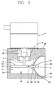
- Figure 3 is a sectional view showing an electrodeless lighting system including a resonator in accordance with the present invention.
- the electrodeless lighting system includes an microwave generator 10 for generating an microwave energy; a resonator 100 having a multi-step type resonating space part 110 for resonating the microwave generated from the microwave generator 10; an microwave feeder 30 mounted in the multi-step type resonating space part 110 of the resonator and guiding the microwave generated from the microwave generator 10 to the multi-step type resonating space part 110; an electrodeless bulb 40 positioned in the multi-step type resonating space part 110, connected to the microwave feeder 30 and generating plasma light by virtue of the resonated microwave energy; a reflector 200 for reflecting light generated from the electrodeless bulb 40 to the front side; and a transparent cover 300 mounted at a front side of the reflector 200, preventing leakage of microwave, and protecting the electrodeless bulb 40.
- the resonator 100 includes a body part 120 having a prescribed shape; a multi-step type resonating space part 110 having one side opened at the body part 120 and a section gradually widening toward the opened side; a transmission space part 130 formed at one side of the body part 120 and communicating with the multi-step type resonating space part 110; and a stub 140 formed with a certain height at an inner wall of the multi-step type resonating space part 110.
- the multi-step type resonating space part 110 includes a backward resonating space 111 having prescribed sectional shape and length; a forward resonating space 112 having certain sectional space and length greater than the size of the section shape of the backward resonating space 111; and a connection space 113 for connecting the backward resonating space 111 and the forward resonating space 112.
- the section of the backward resonating space 111 has a circular shape and the section of the forward resonating space 112 has a square shape as shown in Figure 4.
- the size of the section of the backward resonating space 111 that is, an inner diameter (O.D) of the backward resonating space 111, and the size (I.D) of the section of the microwave feeder 30 positioned in the multi-step type resonating space 110 are in the ratio of 10:1. Namely, if the inner diameter (O.D) of the backward resonating space 111 is 100mm, the size of the section of the microwave feeder 30 is equal to or smaller than 10mm.
- the backward resonating space 111 is longer than the connection space 113, and the connection space 113 is longer than the forward resonating space 112.
- the length of the connection space 113 is greater than 1/4 of a wavelength of a resonance frequency.
- a dielectric layer is coated on the inner circumferential surface of the multi-step type resonating space part 110.
- the transmission space part 130 is formed at the side where the size of the section of the multi-step type resonating space part 110 is the smallest, and communicates with the multi-step type resonating space part 110. That is, the transmission space part 130 communicates with the backward resonating space 111.
- the transmission space part 130 has a certain diameter except for an entrance side.
- the antenna 11 of the microwave generator 10 is positioned in the transmission space part 130 of the resonator and coupled with the resonator 100 therein.
- Figure 6 shows a modification of the multi-step type resonating space part 110.
- the backward resonating space 111 has a circular section and the forward resonating space 112 also has a circular section.
- the multi-step type resonating space 110 can have various shapes.
- the stub 140 is formed at the inner wall of the multi-step type resonating space 110. That is, the stub 140 is formed at an inner circumferential wall of the backward resonating space 111.
- the stub 140 can be positioned anywhere on the inner circumferential wall of the backward resonating space 111, and preferably, it is positioned at the opposite side of the transmission space part 130.
- the stub 140 has a cylindrical form in its section, and preferably, the stub 140 has a diameter equal to or smaller than 20mm and a height equal to or smaller than 15mm.
- the stub 140 can be modified to a hexahedral form with a square-shaped section.
- the stub 140 has width and length equal to or smaller than 20mm, and height equal to or smaller than 15mm.
- the stub 140 can be implemented in various forms.
- the microwave 30 includes a first conductor bar 31 having a certain length, positioned in the transmission space part 130 and connected to the antenna 11; and a second conductor bar 32 having a certain length, positioned at the center of the multi-step type resonating space part 110, and connected to the first conductor bar 31. That is, the second conductor bar 32 is positioned on the central line of the multi-step type resonating space part 110. And as mentioned above, an outer diameter of the second conductor bar 32 is smaller than 1/10 of the inner diameter of the backward resonating space 111.
- a conductor ring 70 for concentrating microwave is coupled to the transmission space unit 130, and the conductor ring 70 is positioned in the boundary region between the multi-step type resonating space part 110 and the transmission space part 130.
- the conductor ring 70 has prescribed thickness and length, and its outer diameter corresponds to the inner diameter of the transmission space part 130.
- the electrodeless bulb 40 includes a bulb portion 41 filled with gas-fill therein and a stem portion 42 extended with prescribed length and outer diameter from an outer circumferential surface of the bulb portion 41.
- the electrodeless bulb 40 is connected to the second conductor bar 32 and positioned at the same level with the second conductor bar 32.
- the reflector 200 includes a curved-surface portion 210 formed to be concave spherical surface; a fixing portion 220 formed extended with a prescribed length at an edge of the curved-surface portion 210; and an insertion portion 230 formed at the other side of the curved-surface portion 210, into which the stem portion 42 of the electrodeless bulb is inserted.
- the length of the curved-surface portion 210 corresponds to the length of the connection space of the multi-step type resonating space part 110.
- the shape of the front side of the fixing portion 220 corresponds to the shape of the forward resonating space 112 of the multi-step type resonating space part 110.
- the front side of the fixing portion 220 is formed in a circular shape
- the front side of the fixing portion 220 is formed in a rectangular shape
- the reflector 200 is inserted into the opening side of the multi-step type resonating space part 110.
- the curved-surface portion 210 is positioned in the connection space 113 and the fixing portion 220 is positioned in the forward resonating space 112.
- the stem portion 42 of the electrodeless bulb 40 is inserted into the insertion portion 230 and the bulb portion 41 is positioned at the inner side of the curved-surface portion 210.
- the cover 300 is fixedly coupled at an entrance of the fixing portion 220 of the reflector.
- the electrodeless lighting system having the resonator is operated as follows.
- the microwave is transferred to the multi-step type resonating space part 110 of the resonator through the microwave feeder 30.
- the microwave is resonated in the multi-step type resonating space part 110, a strong electric field is formed around the electrodeless bulb 40, making gas-fill filled in the electrodeless bulb 40 excited to generate plasma.
- the stub 140 positioned in the multi-step type resonating space part 110 of the resonator controls the electromagnetic field formed in the multi-step type resonating space part 110.
- Plasma generated from the electrodeless bulb 40 emits light, and the light is reflected by the reflection surface of the curved-surface portion 210 of the reflector, illuminating the front side.
- the resonating space for resonating microwave that is, the multi-step type resonating space part 110 has an enlarged opening side, so the size of the reflector 200 positioned at the opening side of the multi-step type resonating space part 110 is big and various in forms, increasing the amount of parallel light reflected by the reflector 200.
- the forward resonating space 112 of the multi-step resonating space part 110 has a rectangular shape, not only light emitted from the electrodeless bulb 40 can be effectively reflected forward together with the cover 300 but also a microwave shielding performance can be improved.
- the impedance matching and the resonance frequency are controlled by adjusting the section size, that is, the inner diameter, of the multi-step type resonating space part 110 and the outer diameter of the microwave feeder 300 positioned in the multi-step type resonating space part 110 and also adjusting the shape or position of the stub 140 formed in the multi-step type resonating space part 110.
- Difficulties in resonance designing that may be considered for the multi-step type resonating space part 110, that is, in such a structure that the size of the section form increases as it goes to the opening side, can be easily solved by the shape or installation position of the stub 140 and the microwave feeder 30.
- the electrodeless lighting system of the present invention has the following advantages.
- the reflector 200 for reflecting light since the reflector 200 for reflecting light has the enlarged size and is varied in its form to increase the amount of reflected parallel light, an illumination performance is enhanced and a utilization range of a product is extended.
- the impedance matching of the microwave exciting the gas filled in the electrodeless bulb 40 and the resonance frequency are controllable, a stronger magnetic field is formed around the electrodeless bulb 40 and a light efficiency is heightened.
Landscapes
- Physics & Mathematics (AREA)
- Engineering & Computer Science (AREA)
- Plasma & Fusion (AREA)
- Electromagnetism (AREA)
- Non-Portable Lighting Devices Or Systems Thereof (AREA)
- Discharge Lamps And Accessories Thereof (AREA)
- Circuit Arrangements For Discharge Lamps (AREA)
Applications Claiming Priority (2)
| Application Number | Priority Date | Filing Date | Title |
|---|---|---|---|
| KR1020030062738A KR100565218B1 (ko) | 2003-09-08 | 2003-09-08 | 무전극 조명기기의 공진기구조 |
| KR2003062738 | 2003-09-08 |
Publications (1)
| Publication Number | Publication Date |
|---|---|
| EP1513218A1 true EP1513218A1 (fr) | 2005-03-09 |
Family
ID=34132244
Family Applications (1)
| Application Number | Title | Priority Date | Filing Date |
|---|---|---|---|
| EP04002022A Withdrawn EP1513218A1 (fr) | 2003-09-08 | 2004-01-30 | Résonateur dans un système d' éclairage sans électrodes |
Country Status (5)
| Country | Link |
|---|---|
| US (1) | US7102276B2 (fr) |
| EP (1) | EP1513218A1 (fr) |
| JP (1) | JP2005085748A (fr) |
| KR (1) | KR100565218B1 (fr) |
| CN (1) | CN100477070C (fr) |
Families Citing this family (1)
| Publication number | Priority date | Publication date | Assignee | Title |
|---|---|---|---|---|
| KR100690675B1 (ko) * | 2005-04-21 | 2007-03-09 | 엘지전자 주식회사 | 무전극 조명기기의 임피던스 매칭 조절 장치 |
Citations (4)
| Publication number | Priority date | Publication date | Assignee | Title |
|---|---|---|---|---|
| EP0450131A1 (fr) * | 1990-04-06 | 1991-10-09 | New Japan Radio Co., Ltd. | Appareil de radiation à micro-ondes sans électrodes |
| JP2001338620A (ja) * | 2000-05-26 | 2001-12-07 | Matsushita Electric Works Ltd | 無電極放電灯点灯装置 |
| US20020141176A1 (en) * | 2001-03-28 | 2002-10-03 | Miodrag Cekic | Method of modifying the spectral distribution of high-intensity ultraviolet lamps |
| US20030020414A1 (en) * | 2000-04-07 | 2003-01-30 | Schmitkons James W. | Microwave excited ultraviolet lamp system with improved lamp cooling |
Family Cites Families (14)
| Publication number | Priority date | Publication date | Assignee | Title |
|---|---|---|---|---|
| US4743315A (en) * | 1984-09-04 | 1988-05-10 | General Electric Company | Ni3 Al alloy of improved ductility based on iron substituent |
| US4821006A (en) * | 1987-01-17 | 1989-04-11 | Murata Manufacturing Co., Ltd. | Dielectric resonator apparatus |
| US4933602A (en) * | 1987-03-11 | 1990-06-12 | Hitachi, Ltd. | Apparatus for generating light by utilizing microwave |
| JPH01104604U (fr) * | 1988-01-06 | 1989-07-14 | ||
| US4887192A (en) * | 1988-11-04 | 1989-12-12 | Fusion Systems Corporation | Electrodeless lamp having compound resonant structure |
| JPH0532889Y2 (fr) * | 1989-04-27 | 1993-08-23 | ||
| DE4236242A1 (de) * | 1992-10-27 | 1994-04-28 | Dornier Gmbh | Verfahren zur Minderung von Russpartikeln in Abgasströmen |
| US5714919A (en) * | 1993-10-12 | 1998-02-03 | Matsushita Electric Industrial Co., Ltd. | Dielectric notch resonator and filter having preadjusted degree of coupling |
| JP3202910B2 (ja) * | 1995-12-04 | 2001-08-27 | 松下電器産業株式会社 | マイクロ波放電ランプ |
| US5786667A (en) * | 1996-08-09 | 1998-07-28 | Fusion Lighting, Inc. | Electrodeless lamp using separate microwave energy resonance modes for ignition and operation |
| JP2001338788A (ja) * | 2000-05-26 | 2001-12-07 | Matsushita Electric Works Ltd | 無電極放電灯を光源とする照明器具 |
| US6737810B2 (en) * | 2000-10-30 | 2004-05-18 | Matsushita Electric Industrial Co., Ltd. | Electrodeless discharge lamp apparatus with adjustable exciting electrodes |
| JP3927387B2 (ja) * | 2001-08-29 | 2007-06-06 | 株式会社オーク製作所 | 無電極ランプシステム |
| KR100390516B1 (ko) * | 2001-09-27 | 2003-07-04 | 엘지전자 주식회사 | 마이크로파를 이용한 무전극 방전 램프장치용 일체형 벌브및 그 제조방법 |
-
2003
- 2003-09-08 KR KR1020030062738A patent/KR100565218B1/ko not_active Expired - Fee Related
-
2004
- 2004-01-14 US US10/756,359 patent/US7102276B2/en not_active Expired - Fee Related
- 2004-01-30 EP EP04002022A patent/EP1513218A1/fr not_active Withdrawn
- 2004-02-09 JP JP2004032132A patent/JP2005085748A/ja active Pending
- 2004-02-24 CN CNB2004100066062A patent/CN100477070C/zh not_active Expired - Fee Related
Patent Citations (4)
| Publication number | Priority date | Publication date | Assignee | Title |
|---|---|---|---|---|
| EP0450131A1 (fr) * | 1990-04-06 | 1991-10-09 | New Japan Radio Co., Ltd. | Appareil de radiation à micro-ondes sans électrodes |
| US20030020414A1 (en) * | 2000-04-07 | 2003-01-30 | Schmitkons James W. | Microwave excited ultraviolet lamp system with improved lamp cooling |
| JP2001338620A (ja) * | 2000-05-26 | 2001-12-07 | Matsushita Electric Works Ltd | 無電極放電灯点灯装置 |
| US20020141176A1 (en) * | 2001-03-28 | 2002-10-03 | Miodrag Cekic | Method of modifying the spectral distribution of high-intensity ultraviolet lamps |
Non-Patent Citations (2)
| Title |
|---|
| PATENT ABSTRACTS OF JAPAN vol. 1999, no. 07 31 March 1999 (1999-03-31) * |
| PATENT ABSTRACTS OF JAPAN vol. 2002, no. 04 4 August 2002 (2002-08-04) * |
Also Published As
| Publication number | Publication date |
|---|---|
| KR20050025804A (ko) | 2005-03-14 |
| US20050052115A1 (en) | 2005-03-10 |
| JP2005085748A (ja) | 2005-03-31 |
| US7102276B2 (en) | 2006-09-05 |
| CN100477070C (zh) | 2009-04-08 |
| KR100565218B1 (ko) | 2006-03-30 |
| CN1596055A (zh) | 2005-03-16 |
Similar Documents
| Publication | Publication Date | Title |
|---|---|---|
| US8089203B2 (en) | Light source | |
| CA2742819C (fr) | Source de lumiere hyperfrequence a guide d'ondes dielectrique solide | |
| US7161304B2 (en) | Electrodeless lighting system | |
| JP5443595B2 (ja) | マイクロ波で駆動される光源 | |
| EP1458011B1 (fr) | Système de lampe sans électrodes | |
| US8461761B2 (en) | Lucent plasma crucible | |
| US20050047139A1 (en) | Electrodeless lighting system | |
| US7102276B2 (en) | Resonator of electrodeless lighting system | |
| JPS637427B2 (fr) | ||
| US7081707B2 (en) | Waveguide system for electrodeless lighting device | |
| US20110309744A1 (en) | Light source | |
| JP4259274B2 (ja) | マイクロ波無電極放電灯装置 | |
| EP2731124B1 (fr) | Appareil d'éclairage | |
| KR100556788B1 (ko) | 플라즈마 램프 시스템의 전구 | |
| KR100393818B1 (ko) | 마이크로파를 이용한 조명시스템 | |
| JPS5923613B2 (ja) | 高周波放電光源装置 | |
| JP3178368B2 (ja) | 高周波無電極放電ランプ光反射器と高周波無電極放電ランプ装置 | |
| JPS6326881Y2 (fr) | ||
| KR100556781B1 (ko) | 플라즈마 램프 시스템의 전구 | |
| KR101376620B1 (ko) | 무전극 조명기기 | |
| KR20020059536A (ko) | 마그네트론 일체형 마이크로파 조명 장치 | |
| KR20080071423A (ko) | 마이크로웨이브 램프 시스템 |
Legal Events
| Date | Code | Title | Description |
|---|---|---|---|
| PUAI | Public reference made under article 153(3) epc to a published international application that has entered the european phase |
Free format text: ORIGINAL CODE: 0009012 |
|
| AK | Designated contracting states |
Kind code of ref document: A1 Designated state(s): AT BE BG CH CY CZ DE DK EE ES FI FR GB GR HU IE IT LI LU MC NL PT RO SE SI SK TR |
|
| AX | Request for extension of the european patent |
Extension state: AL LT LV MK |
|
| 17P | Request for examination filed |
Effective date: 20050324 |
|
| AKX | Designation fees paid |
Designated state(s): DE GB IT |
|
| 17Q | First examination report despatched |
Effective date: 20070327 |
|
| STAA | Information on the status of an ep patent application or granted ep patent |
Free format text: STATUS: THE APPLICATION HAS BEEN WITHDRAWN |
|
| 18W | Application withdrawn |
Effective date: 20070806 |