EP0450243A2 - Elektromagnetischer Positions- und Orientationssensor - Google Patents
Elektromagnetischer Positions- und Orientationssensor Download PDFInfo
- Publication number
- EP0450243A2 EP0450243A2 EP90403349A EP90403349A EP0450243A2 EP 0450243 A2 EP0450243 A2 EP 0450243A2 EP 90403349 A EP90403349 A EP 90403349A EP 90403349 A EP90403349 A EP 90403349A EP 0450243 A2 EP0450243 A2 EP 0450243A2
- Authority
- EP
- European Patent Office
- Prior art keywords
- coils
- sensor
- transmitter
- calculation means
- signal
- Prior art date
- Legal status (The legal status is an assumption and is not a legal conclusion. Google has not performed a legal analysis and makes no representation as to the accuracy of the status listed.)
- Granted
Links
Images
Classifications
-
- F—MECHANICAL ENGINEERING; LIGHTING; HEATING; WEAPONS; BLASTING
- F41—WEAPONS
- F41G—WEAPON SIGHTS; AIMING
- F41G3/00—Aiming or laying means
- F41G3/005—Aiming or laying means with means for correcting the parallax between the sighting means and the muzzle axis
-
- F—MECHANICAL ENGINEERING; LIGHTING; HEATING; WEAPONS; BLASTING
- F41—WEAPONS
- F41G—WEAPON SIGHTS; AIMING
- F41G3/00—Aiming or laying means
- F41G3/22—Aiming or laying means for vehicle-borne armament, e.g. on aircraft
- F41G3/225—Helmet sighting systems
-
- G—PHYSICS
- G01—MEASURING; TESTING
- G01B—MEASURING LENGTH, THICKNESS OR SIMILAR LINEAR DIMENSIONS; MEASURING ANGLES; MEASURING AREAS; MEASURING IRREGULARITIES OF SURFACES OR CONTOURS
- G01B7/00—Measuring arrangements characterised by the use of electric or magnetic techniques
- G01B7/004—Measuring arrangements characterised by the use of electric or magnetic techniques for measuring coordinates of points
Definitions
- the present invention relates to an electromagnetic detector designed to identify the position and orientation of a movable body in a given space and in particular to identify the exact position, in an airplane, of the helmet, equipped with a helmet sight, which is worn the pilot.
- An electromagnetic position and orientation detector generally comprises a fixed transmitter with three coils excited alternately by a generator and a mobile sensor with three coils, to supply, by each of its coils, an induced signal relating to the excitation of each of the transmitter coils; calculation means coupled to the sensor coils make it possible to determine, as a function of the induced signals, the position and orientation of the sensor.
- the cabin of the airplane constitutes the given space and the helmet the mobile body.
- Such detectors are described, for example in French patents 2 458 838 and US 4 396 885.
- the transmitter occupies a fixed place in space and the sensor is attached to the movable body.
- the sensor For each position of the body correspond, for each coil of the sensor, three signals which are induced respectively by the three coils of the transmitter; in total these are nine induced signals which are used to calculate the position and direction of the body.
- the object of the present invention is to avoid or at least reduce the drawbacks of these detectors.
- the subject of the present invention is a fixed sensor, the signal of which serves as a reference signal for, during calculations, correcting the errors brought about by the nine induced signals, as defined by claim 1.
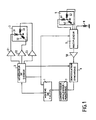
- the electromagnetic position and orientation detector according to the invention is produced from a known detector; the operation of such a detector is recalled below, with the help of FIG. 1, but without taking account for the moment of the element 8 which is specific to the invention.
- the transmitter 3 and the sensor 4 are most often produced using triplets 31, 32, 33 and 41, 42, 43 of coils orthogonal to each other, arranged along the axes, not shown of a reference trihedron.
- the processing device generally comprises, in series from the outputs of the sensor 4: a multiplexer, 5, an amplifier, 50, a synchronous demodulator, 6, an analog-digital converter, 7 and calculation means, 1 , formed from a microprocessor.
- the calculation means trigger the signal generator 2 which supplies an excitation signal to supply one after the other and separately the coils 31, 32, 33 of the transmitter, during successive supply cycles.
- a cycle partition signal formed by a cycle start pulse followed by nine pulses regularly distributed over the duration of a cycle, is supplied by the generator 2 on a control input of the multiplexer 5; the latter can thus separately and successively connect the three coils 41, 42, 43 of the sensor 4, to the input of the amplifier 50 during the time, where a coil of the transmitter is supplied during a cycle; during a cycle the multiplexer 5 thus delivers nine signals corresponding to the signals successively induced by the three coils of the transmitter 3 in each of the three coils of the sensor 4.
- the synchronous demodulator 6 performs a demodulation of the signals supplied by the amplifier 50, by virtue of the excitation signal which is permanently supplied to it, as soon as it is triggered, the generator 2.
- the partition signal is also supplied to the calculation means 1 to enable them to recognize the source of the signals which reach them through the converter 7.
- the first method uses the laws of electromagnetism which give formulas for predicting fields created at all points.
- Characteristic values which do not depend on the rotation of the sensor but only on its position, are calculated from the nine field measurements made in the reference frame that constitutes the sensor. Thanks to these six parameters and the laws of electromagnetism, the position of the sensor relative to the transmitter is calculated.
- the nine components of the fields are calculated in the reference frame of the transmitter.
- the comparison of these nine components to those seen by the sensor gives the relative rotation of the sensor relative to the transmitter.
- the second method uses a preliminary experimental survey of the fields in space, with a sensor having a defined orientation, which makes it possible to get rid of the distortions due either to the metallic masses present in the vicinity, or to the imperfections of the emitter and sensor compared to electromagnetic theory.
- the detectors described below make it possible to overcome this drawback and can be used with one or the other of the two methods of extracting position and orientation previously mentioned. They simply require that the differences in constitution between the receiver coils and the reference coil be negligible or be measured and known elsewhere.
- the detector differs from a conventional detector by the addition of a fixed sensor 8 produced using a coil whose position and orientation are known with precision in the reference trihedron of the transmitter 3.
- the coil of the fixed sensor 8 is treated in the same way as the coils 41, 42, 43 of the mobile sensor 4, that is to say that its induced signal is supplied to the multiplexer 5.
- the multiplexer 5 therefore has an input of signal more than the corresponding multiplexer of a conventional detector; the partition signal which it receives from the signal generator 2 is then formed by a cycle start pulse followed, not by nine, but by twelve pulses regularly distributed over the duration of a cycle, since each time that one of the three coils of the transmitter 3 is energized, the signals induced in the four coils of sensors must be successively taken into account.
- the measurement of the signal induced in the fixed sensor 8 compared with the theoretical value that this signal should have because of its position and its orientation in the first method of determining the position and the orientation described above, or compared with the value of the signal induced in the sensor 8 during the experimental survey of the fields in the second method described above, makes it possible to correct, in the nine measurements made per cycle with mobile sensor, the errors due to the emission chains, reception and measurement; the procedure for making these corrections is described below, considering two cases.
- the first case is that where the detector according to FIG. 1 is linear both in its three transmission channels and in its measurement channel and where, at the time of measurement, the reception channel exhibits a gain error Gr and each transmission channel gain error Gej, where j is the reference of the transmitter coil of the channel considered reduced by 30.
- M′ij Mij.M′4d / M4j
- M′ij can therefore be calculated since Mij and M4j are calculated and that, in the first determination method described above, M′4j will be the theoretical value of the coupling calculated for the sensor 8, while, in the second method, this will be the value recorded during the experimental measurement of the fields.
- the second case to consider is that where the detector is not linear in its emission and measurement channels.
- ej is the level commanded on the coil j of the transmitter
- ri is the level actually received on the coil i of the sensor 8
- the coefficients of order 1 of the functions hij and h4j that is to say kij and k4j, are determined.
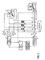
- FIG. 2 is a diagram of a detector according to the invention in which the measurement reference, instead of being given by a fixed sensor in free field such as the sensor 8 in FIG. 1, is given by three transformers 9a , 9b, 9c; the primary windings of these transformers are connected in series with the coils of a transmitter 3 similar to that of the Figure 1, for example the primary winding of the transformer 9a with the coil 31; the secondary windings of these transformers are connected in series between the output of a multiplexer 5 and the input of an amplifier 50; these two circuits are similar to circuits 5 and 50 of FIG. 1 with the difference that the multiplexer requires only three signal inputs.
- Switches 91, 92, 93 are mounted in parallel respectively on the secondary windings of these transformers and are controlled using the partition signal which has already been discussed in the description of Figure 1. For the rest of the circuit Figure 2 is identical to Figure 1.
- the partition signal is formed by a cycle start pulse followed no longer by twelve but by eighteen pulses regularly distributed over the duration of the cycle; in these eighteen successive pulses, the pulses of odd rank are used, by the multiplexer 5, as in the case of a conventional detector having no other electromagnetic coupling than that between the transmitter 3 and the mobile sensor 4, that is to say that they serve for the time multiplexing of the signals induced in each of the coils of the mobile sensor 4 by each of the coils of the transmitter 3; as for the nine pulses of even rank, they are used by a decoder 10 to control the opening of one and only one of the switches 9a, 9b, 9c; this opening of a switch takes place during half the duration of taking into account each of the three induced signals created by the excitation signal applied to the coil of the transmitter 3 which is in series with the transformer primary on the secondary of which the switch in question is mounted.
- the present invention is not limited to the examples described, this is how, in particular, the assembly according to FIG. 2 can be modified by placing the secondary of the transformers 9a, 9b, 9c not in series on the output of the multiplexer 5 but by connecting them each to an input of a multiplexer 5 which would have six signal inputs.
- the partition signal should then comprise, per cycle, one cycle start pulse and twelve pulses regularly distributed over the duration of the cycle so that, while one of the coils of the transmitter 3 receives the excitation signal from the generator 2, the signals induced in the three coils of the movable sensor 4 and in the secondary of the transformer are successively taken into account, the primary of which receives the excitation signal, i.e. the primary of which is in series with that of the transmitter coils which is energized.
Landscapes
- Engineering & Computer Science (AREA)
- General Engineering & Computer Science (AREA)
- Physics & Mathematics (AREA)
- General Physics & Mathematics (AREA)
- Aviation & Aerospace Engineering (AREA)
- Measurement Of Length, Angles, Or The Like Using Electric Or Magnetic Means (AREA)
- Position Fixing By Use Of Radio Waves (AREA)
Applications Claiming Priority (2)
| Application Number | Priority Date | Filing Date | Title |
|---|---|---|---|
| FR8915881 | 1989-12-01 | ||
| FR8915881A FR2655415B1 (fr) | 1989-12-01 | 1989-12-01 | Detecteur electromagnetique de position et d'orientation. |
Publications (3)
| Publication Number | Publication Date |
|---|---|
| EP0450243A2 true EP0450243A2 (de) | 1991-10-09 |
| EP0450243A3 EP0450243A3 (en) | 1991-10-23 |
| EP0450243B1 EP0450243B1 (de) | 1993-12-29 |
Family
ID=9388039
Family Applications (1)
| Application Number | Title | Priority Date | Filing Date |
|---|---|---|---|
| EP90403349A Expired - Lifetime EP0450243B1 (de) | 1989-12-01 | 1990-11-27 | Elektromagnetischer Positions- und Orientationssensor |
Country Status (7)
| Country | Link |
|---|---|
| US (1) | US5109194A (de) |
| EP (1) | EP0450243B1 (de) |
| JP (1) | JPH03235019A (de) |
| CA (1) | CA2031133A1 (de) |
| DE (1) | DE69005614T2 (de) |
| FR (1) | FR2655415B1 (de) |
| HK (1) | HK83696A (de) |
Families Citing this family (80)
| Publication number | Priority date | Publication date | Assignee | Title |
|---|---|---|---|---|
| FR2652928B1 (fr) | 1989-10-05 | 1994-07-29 | Diadix Sa | Systeme interactif d'intervention locale a l'interieur d'une zone d'une structure non homogene. |
| DE4224225C2 (de) * | 1992-07-22 | 1996-03-14 | Walter Dr Mehnert | Schaltungsanordnung für einen induktiven Stellungsgeber |
| US5913820A (en) | 1992-08-14 | 1999-06-22 | British Telecommunications Public Limited Company | Position location system |
| US5453686A (en) * | 1993-04-08 | 1995-09-26 | Polhemus Incorporated | Pulsed-DC position and orientation measurement system |
| US5558091A (en) * | 1993-10-06 | 1996-09-24 | Biosense, Inc. | Magnetic determination of position and orientation |
| US6327381B1 (en) | 1994-12-29 | 2001-12-04 | Worldscape, Llc | Image transformation and synthesis methods |
| US6690963B2 (en) | 1995-01-24 | 2004-02-10 | Biosense, Inc. | System for determining the location and orientation of an invasive medical instrument |
| US5640170A (en) * | 1995-06-05 | 1997-06-17 | Polhemus Incorporated | Position and orientation measuring system having anti-distortion source configuration |
| US5592939A (en) | 1995-06-14 | 1997-01-14 | Martinelli; Michael A. | Method and system for navigating a catheter probe |
| US6054951A (en) * | 1995-08-28 | 2000-04-25 | Sypniewski; Jozef | Multi-dimensional tracking sensor |
| CA2188246A1 (en) * | 1995-10-20 | 1997-04-21 | James V. Raso | Feedback system for monitoring position and orientation |
| US6226548B1 (en) | 1997-09-24 | 2001-05-01 | Surgical Navigation Technologies, Inc. | Percutaneous registration apparatus and method for use in computer-assisted surgical navigation |
| US6104944A (en) * | 1997-11-17 | 2000-08-15 | Martinelli; Michael A. | System and method for navigating a multiple electrode catheter |
| US6021343A (en) | 1997-11-20 | 2000-02-01 | Surgical Navigation Technologies | Image guided awl/tap/screwdriver |
| US6348058B1 (en) | 1997-12-12 | 2002-02-19 | Surgical Navigation Technologies, Inc. | Image guided spinal surgery guide, system, and method for use thereof |
| US6477400B1 (en) | 1998-08-20 | 2002-11-05 | Sofamor Danek Holdings, Inc. | Fluoroscopic image guided orthopaedic surgery system with intraoperative registration |
| US6470207B1 (en) | 1999-03-23 | 2002-10-22 | Surgical Navigation Technologies, Inc. | Navigational guidance via computer-assisted fluoroscopic imaging |
| US6491699B1 (en) * | 1999-04-20 | 2002-12-10 | Surgical Navigation Technologies, Inc. | Instrument guidance method and system for image guided surgery |
| US8239001B2 (en) | 2003-10-17 | 2012-08-07 | Medtronic Navigation, Inc. | Method and apparatus for surgical navigation |
| US7366562B2 (en) | 2003-10-17 | 2008-04-29 | Medtronic Navigation, Inc. | Method and apparatus for surgical navigation |
| US6381485B1 (en) | 1999-10-28 | 2002-04-30 | Surgical Navigation Technologies, Inc. | Registration of human anatomy integrated for electromagnetic localization |
| US6499488B1 (en) | 1999-10-28 | 2002-12-31 | Winchester Development Associates | Surgical sensor |
| US6493573B1 (en) | 1999-10-28 | 2002-12-10 | Winchester Development Associates | Method and system for navigating a catheter probe in the presence of field-influencing objects |
| US6379302B1 (en) | 1999-10-28 | 2002-04-30 | Surgical Navigation Technologies Inc. | Navigation information overlay onto ultrasound imagery |
| US8644907B2 (en) | 1999-10-28 | 2014-02-04 | Medtronic Navigaton, Inc. | Method and apparatus for surgical navigation |
| US6474341B1 (en) | 1999-10-28 | 2002-11-05 | Surgical Navigation Technologies, Inc. | Surgical communication and power system |
| US11331150B2 (en) | 1999-10-28 | 2022-05-17 | Medtronic Navigation, Inc. | Method and apparatus for surgical navigation |
| US6725080B2 (en) | 2000-03-01 | 2004-04-20 | Surgical Navigation Technologies, Inc. | Multiple cannula image guided tool for image guided procedures |
| US6535756B1 (en) | 2000-04-07 | 2003-03-18 | Surgical Navigation Technologies, Inc. | Trajectory storage apparatus and method for surgical navigation system |
| US7085400B1 (en) | 2000-06-14 | 2006-08-01 | Surgical Navigation Technologies, Inc. | System and method for image based sensor calibration |
| JP2002054928A (ja) * | 2000-08-14 | 2002-02-20 | Reideikku:Kk | 方位測定方法及び測定装置 |
| US6636757B1 (en) | 2001-06-04 | 2003-10-21 | Surgical Navigation Technologies, Inc. | Method and apparatus for electromagnetic navigation of a surgical probe near a metal object |
| US7239345B1 (en) | 2001-10-12 | 2007-07-03 | Worldscape, Inc. | Camera arrangements with backlighting detection and methods of using same |
| US6947786B2 (en) | 2002-02-28 | 2005-09-20 | Surgical Navigation Technologies, Inc. | Method and apparatus for perspective inversion |
| US6990368B2 (en) | 2002-04-04 | 2006-01-24 | Surgical Navigation Technologies, Inc. | Method and apparatus for virtual digital subtraction angiography |
| US7998062B2 (en) | 2004-03-29 | 2011-08-16 | Superdimension, Ltd. | Endoscope structures and techniques for navigating to a target in branched structure |
| US6892090B2 (en) | 2002-08-19 | 2005-05-10 | Surgical Navigation Technologies, Inc. | Method and apparatus for virtual endoscopy |
| US7599730B2 (en) | 2002-11-19 | 2009-10-06 | Medtronic Navigation, Inc. | Navigation system for cardiac therapies |
| US7697972B2 (en) | 2002-11-19 | 2010-04-13 | Medtronic Navigation, Inc. | Navigation system for cardiac therapies |
| US7542791B2 (en) | 2003-01-30 | 2009-06-02 | Medtronic Navigation, Inc. | Method and apparatus for preplanning a surgical procedure |
| US7660623B2 (en) | 2003-01-30 | 2010-02-09 | Medtronic Navigation, Inc. | Six degree of freedom alignment display for medical procedures |
| US7570791B2 (en) | 2003-04-25 | 2009-08-04 | Medtronic Navigation, Inc. | Method and apparatus for performing 2D to 3D registration |
| US7313430B2 (en) * | 2003-08-28 | 2007-12-25 | Medtronic Navigation, Inc. | Method and apparatus for performing stereotactic surgery |
| EP1667749B1 (de) | 2003-09-15 | 2009-08-05 | Super Dimension Ltd. | System aus zubehör zur verwendung mit bronchoskopen |
| EP2316328B1 (de) | 2003-09-15 | 2012-05-09 | Super Dimension Ltd. | Umhüllungsvorrichtung zur Fixierung von Bronchoskopen |
| US7835778B2 (en) | 2003-10-16 | 2010-11-16 | Medtronic Navigation, Inc. | Method and apparatus for surgical navigation of a multiple piece construct for implantation |
| US7840253B2 (en) | 2003-10-17 | 2010-11-23 | Medtronic Navigation, Inc. | Method and apparatus for surgical navigation |
| US8764725B2 (en) | 2004-02-09 | 2014-07-01 | Covidien Lp | Directional anchoring mechanism, method and applications thereof |
| US7567834B2 (en) | 2004-05-03 | 2009-07-28 | Medtronic Navigation, Inc. | Method and apparatus for implantation between two vertebral bodies |
| US7636595B2 (en) | 2004-10-28 | 2009-12-22 | Medtronic Navigation, Inc. | Method and apparatus for calibrating non-linear instruments |
| JPWO2006049239A1 (ja) * | 2004-11-04 | 2008-05-29 | 株式会社フィアモ | 試験対象液中の超微量金属元素をリアルタイム・インラインで検出する方法及びその装置 |
| US7835784B2 (en) | 2005-09-21 | 2010-11-16 | Medtronic Navigation, Inc. | Method and apparatus for positioning a reference frame |
| US9168102B2 (en) | 2006-01-18 | 2015-10-27 | Medtronic Navigation, Inc. | Method and apparatus for providing a container to a sterile environment |
| US8112292B2 (en) | 2006-04-21 | 2012-02-07 | Medtronic Navigation, Inc. | Method and apparatus for optimizing a therapy |
| US8660635B2 (en) | 2006-09-29 | 2014-02-25 | Medtronic, Inc. | Method and apparatus for optimizing a computer assisted surgical procedure |
| US8905920B2 (en) | 2007-09-27 | 2014-12-09 | Covidien Lp | Bronchoscope adapter and method |
| US9575140B2 (en) | 2008-04-03 | 2017-02-21 | Covidien Lp | Magnetic interference detection system and method |
| EP2297673B1 (de) | 2008-06-03 | 2020-04-22 | Covidien LP | Registrationsverfahren auf merkmalbasis |
| US8218847B2 (en) | 2008-06-06 | 2012-07-10 | Superdimension, Ltd. | Hybrid registration method |
| US8932207B2 (en) | 2008-07-10 | 2015-01-13 | Covidien Lp | Integrated multi-functional endoscopic tool |
| US8165658B2 (en) | 2008-09-26 | 2012-04-24 | Medtronic, Inc. | Method and apparatus for positioning a guide relative to a base |
| US8175681B2 (en) | 2008-12-16 | 2012-05-08 | Medtronic Navigation Inc. | Combination of electromagnetic and electropotential localization |
| US8611984B2 (en) | 2009-04-08 | 2013-12-17 | Covidien Lp | Locatable catheter |
| US8494613B2 (en) | 2009-08-31 | 2013-07-23 | Medtronic, Inc. | Combination localization system |
| US8494614B2 (en) | 2009-08-31 | 2013-07-23 | Regents Of The University Of Minnesota | Combination localization system |
| US10582834B2 (en) | 2010-06-15 | 2020-03-10 | Covidien Lp | Locatable expandable working channel and method |
| US10952593B2 (en) | 2014-06-10 | 2021-03-23 | Covidien Lp | Bronchoscope adapter |
| US10426555B2 (en) | 2015-06-03 | 2019-10-01 | Covidien Lp | Medical instrument with sensor for use in a system and method for electromagnetic navigation |
| US9962134B2 (en) | 2015-10-28 | 2018-05-08 | Medtronic Navigation, Inc. | Apparatus and method for maintaining image quality while minimizing X-ray dosage of a patient |
| US10478254B2 (en) | 2016-05-16 | 2019-11-19 | Covidien Lp | System and method to access lung tissue |
| US10638952B2 (en) | 2016-10-28 | 2020-05-05 | Covidien Lp | Methods, systems, and computer-readable media for calibrating an electromagnetic navigation system |
| US10615500B2 (en) | 2016-10-28 | 2020-04-07 | Covidien Lp | System and method for designing electromagnetic navigation antenna assemblies |
| US10792106B2 (en) | 2016-10-28 | 2020-10-06 | Covidien Lp | System for calibrating an electromagnetic navigation system |
| US10446931B2 (en) | 2016-10-28 | 2019-10-15 | Covidien Lp | Electromagnetic navigation antenna assembly and electromagnetic navigation system including the same |
| US10722311B2 (en) | 2016-10-28 | 2020-07-28 | Covidien Lp | System and method for identifying a location and/or an orientation of an electromagnetic sensor based on a map |
| US10751126B2 (en) | 2016-10-28 | 2020-08-25 | Covidien Lp | System and method for generating a map for electromagnetic navigation |
| US10418705B2 (en) | 2016-10-28 | 2019-09-17 | Covidien Lp | Electromagnetic navigation antenna assembly and electromagnetic navigation system including the same |
| US10517505B2 (en) | 2016-10-28 | 2019-12-31 | Covidien Lp | Systems, methods, and computer-readable media for optimizing an electromagnetic navigation system |
| US11219489B2 (en) | 2017-10-31 | 2022-01-11 | Covidien Lp | Devices and systems for providing sensors in parallel with medical tools |
| US12089902B2 (en) | 2019-07-30 | 2024-09-17 | Coviden Lp | Cone beam and 3D fluoroscope lung navigation |
Family Cites Families (11)
| Publication number | Priority date | Publication date | Assignee | Title |
|---|---|---|---|---|
| US4054881A (en) * | 1976-04-26 | 1977-10-18 | The Austin Company | Remote object position locater |
| FR2458838A1 (fr) * | 1979-06-06 | 1981-01-02 | Thomson Csf | Dispositif de mesure de l'orientation relative de deux corps et systeme de reperage de direction correspondant |
| US4394831A (en) * | 1981-02-12 | 1983-07-26 | Honeywell Inc. | Helmet metal mass compensation for helmet-mounted sighting system |
| JPS59672A (ja) * | 1982-06-27 | 1984-01-05 | Tsutomu Jinno | 測距センサ |
| US4613866A (en) * | 1983-05-13 | 1986-09-23 | Mcdonnell Douglas Corporation | Three dimensional digitizer with electromagnetic coupling |
| US4642786A (en) * | 1984-05-25 | 1987-02-10 | Position Orientation Systems, Ltd. | Method and apparatus for position and orientation measurement using a magnetic field and retransmission |
| US4737794A (en) * | 1985-12-09 | 1988-04-12 | Mcdonnell Douglas Corporation | Method and apparatus for determining remote object orientation and position |
| US4849692A (en) * | 1986-10-09 | 1989-07-18 | Ascension Technology Corporation | Device for quantitatively measuring the relative position and orientation of two bodies in the presence of metals utilizing direct current magnetic fields |
| US4945305A (en) * | 1986-10-09 | 1990-07-31 | Ascension Technology Corporation | Device for quantitatively measuring the relative position and orientation of two bodies in the presence of metals utilizing direct current magnetic fields |
| GB8625365D0 (en) * | 1986-10-23 | 1986-11-26 | Radiodetection Ltd | Positional information systems |
| US4829250A (en) * | 1988-02-10 | 1989-05-09 | Honeywell, Inc. | Magnetic direction finding device with improved accuracy |
-
1989
- 1989-12-01 FR FR8915881A patent/FR2655415B1/fr not_active Expired - Fee Related
-
1990
- 1990-11-27 DE DE69005614T patent/DE69005614T2/de not_active Expired - Fee Related
- 1990-11-27 EP EP90403349A patent/EP0450243B1/de not_active Expired - Lifetime
- 1990-11-29 CA CA002031133A patent/CA2031133A1/fr not_active Abandoned
- 1990-11-30 JP JP2336905A patent/JPH03235019A/ja active Pending
- 1990-12-03 US US07/620,650 patent/US5109194A/en not_active Expired - Fee Related
-
1996
- 1996-05-09 HK HK83696A patent/HK83696A/xx not_active IP Right Cessation
Also Published As
| Publication number | Publication date |
|---|---|
| EP0450243A3 (en) | 1991-10-23 |
| DE69005614D1 (de) | 1994-02-10 |
| CA2031133A1 (fr) | 1991-06-02 |
| EP0450243B1 (de) | 1993-12-29 |
| HK83696A (en) | 1996-05-17 |
| FR2655415A1 (fr) | 1991-06-07 |
| DE69005614T2 (de) | 1994-06-16 |
| JPH03235019A (ja) | 1991-10-21 |
| FR2655415B1 (fr) | 1992-02-21 |
| US5109194A (en) | 1992-04-28 |
Similar Documents
| Publication | Publication Date | Title |
|---|---|---|
| EP0450243B1 (de) | Elektromagnetischer Positions- und Orientationssensor | |
| EP0021906B1 (de) | Vorrichtung zur Messung der relativen Orientierung zweier Körper und entsprechendes System zur Richtungsbestimmung | |
| EP0745827B1 (de) | Verfahren zur Bestimmung der Position und Orientierung eines beweglichen Objektes, insbesondere der Blickrichtung eines Helmsichtgeräts | |
| EP0478420B1 (de) | Systeme zur elektromagnetischen Bestimmung von Position und Lage eines beweglichen Körpers | |
| WO2001055746A1 (en) | Optical distance measurement | |
| EP1601929B1 (de) | Verfahren und vorrichtung zur magnetischen messung der lage und orientierung eines, relativ zu einer feststehenden struktur, bewegbaren objekts | |
| US20030139895A1 (en) | Magnetic device, and method for determining orientation | |
| EP0267840A1 (de) | Verfahren und Gerät zur Positionsbestimmung von Unterwasserobjekten mit Bezug auf das sie ziehende Schiff | |
| EP1387505A2 (de) | Intensitätsrauschverminderung mit einem Kalmanfilter in heterodynen optischen Empfängern | |
| EP1272863A1 (de) | Anordnung und verfahren zur magnetfeldmessung mit superponiertem kalibration und korrespondierenden anwendungen | |
| US9374158B2 (en) | Electronic wavefront correction for free-space optical communications | |
| WO1993013435A1 (fr) | Dispositif electronique de multiplexage de plusieurs charges excitees en courant alternatif | |
| EP0055636B1 (de) | Abweichungsempfänger für Sekundärradar | |
| EP3710869B1 (de) | Verfahren zur kompensation eines magnetischen lokalisators, lokalisator und computerprogramm | |
| FR2815416A1 (fr) | Mesure vectorielle amelioree d'un champ magnetique | |
| GB2533124A (en) | Underwater detection | |
| CA2164381A1 (fr) | Restitution de pointage en elevation, notamment pour radar a synthese d'ouverture | |
| EP0169758A1 (de) | Verfahren und Vorrichtung zur Bestimmung der Ortung eines Objektes im Raum und Anwendung bei der Schusssimulation | |
| EP0053963A1 (de) | Quantifizierungsanordnung für Pulssignale für Sekundärradar | |
| Bekhtin et al. | Tuning Parameters of IR-sensor in Control Systems | |
| Ramon | Verification of the Complex Internal Calibration Approach Operated for the Sentinel-1A C-SAR Instrument | |
| FR2831258A1 (fr) | Procede et dispositif de mesure magnetique de la position et de l'orientation d'un objet mobile par rapport a une structure fixe | |
| FR2505508A1 (fr) | Dispositif de detection d'objets metalliques | |
| CN118259299A (zh) | 数据处理装置、深度检测装置与数据处理方法 | |
| EP0078198A1 (de) | Verfahren zum Ermitteln von Fehlern in einem metallischen Werkstoff mittels Wirbelströmen |
Legal Events
| Date | Code | Title | Description |
|---|---|---|---|
| PUAI | Public reference made under article 153(3) epc to a published international application that has entered the european phase |
Free format text: ORIGINAL CODE: 0009012 |
|
| PUAL | Search report despatched |
Free format text: ORIGINAL CODE: 0009013 |
|
| AK | Designated contracting states |
Kind code of ref document: A2 Designated state(s): BE CH DE FR GB IT LI NL SE |
|
| AK | Designated contracting states |
Kind code of ref document: A3 Designated state(s): BE CH DE FR GB IT LI NL SE |
|
| 17P | Request for examination filed |
Effective date: 19920213 |
|
| 17Q | First examination report despatched |
Effective date: 19930420 |
|
| GRAA | (expected) grant |
Free format text: ORIGINAL CODE: 0009210 |
|
| AK | Designated contracting states |
Kind code of ref document: B1 Designated state(s): BE CH DE FR GB IT LI NL SE |
|
| ITF | It: translation for a ep patent filed | ||
| REF | Corresponds to: |
Ref document number: 69005614 Country of ref document: DE Date of ref document: 19940210 |
|
| GBT | Gb: translation of ep patent filed (gb section 77(6)(a)/1977) |
Effective date: 19940307 |
|
| PLBE | No opposition filed within time limit |
Free format text: ORIGINAL CODE: 0009261 |
|
| STAA | Information on the status of an ep patent application or granted ep patent |
Free format text: STATUS: NO OPPOSITION FILED WITHIN TIME LIMIT |
|
| 26N | No opposition filed | ||
| EAL | Se: european patent in force in sweden |
Ref document number: 90403349.5 |
|
| PGFP | Annual fee paid to national office [announced via postgrant information from national office to epo] |
Ref country code: CH Payment date: 19981013 Year of fee payment: 9 |
|
| PGFP | Annual fee paid to national office [announced via postgrant information from national office to epo] |
Ref country code: NL Payment date: 19981015 Year of fee payment: 9 |
|
| PGFP | Annual fee paid to national office [announced via postgrant information from national office to epo] |
Ref country code: SE Payment date: 19981016 Year of fee payment: 9 Ref country code: DE Payment date: 19981016 Year of fee payment: 9 |
|
| PGFP | Annual fee paid to national office [announced via postgrant information from national office to epo] |
Ref country code: GB Payment date: 19981019 Year of fee payment: 9 |
|
| PGFP | Annual fee paid to national office [announced via postgrant information from national office to epo] |
Ref country code: BE Payment date: 19981109 Year of fee payment: 9 |
|
| PGFP | Annual fee paid to national office [announced via postgrant information from national office to epo] |
Ref country code: FR Payment date: 19981125 Year of fee payment: 9 |
|
| PG25 | Lapsed in a contracting state [announced via postgrant information from national office to epo] |
Ref country code: GB Free format text: LAPSE BECAUSE OF NON-PAYMENT OF DUE FEES Effective date: 19991127 |
|
| PG25 | Lapsed in a contracting state [announced via postgrant information from national office to epo] |
Ref country code: SE Free format text: LAPSE BECAUSE OF NON-PAYMENT OF DUE FEES Effective date: 19991128 |
|
| PG25 | Lapsed in a contracting state [announced via postgrant information from national office to epo] |
Ref country code: LI Free format text: LAPSE BECAUSE OF NON-PAYMENT OF DUE FEES Effective date: 19991130 Ref country code: CH Free format text: LAPSE BECAUSE OF NON-PAYMENT OF DUE FEES Effective date: 19991130 Ref country code: BE Free format text: LAPSE BECAUSE OF NON-PAYMENT OF DUE FEES Effective date: 19991130 |
|
| BERE | Be: lapsed |
Owner name: SEXTANT AVIONIQUE Effective date: 19991130 |
|
| PG25 | Lapsed in a contracting state [announced via postgrant information from national office to epo] |
Ref country code: NL Free format text: LAPSE BECAUSE OF NON-PAYMENT OF DUE FEES Effective date: 20000601 |
|
| REG | Reference to a national code |
Ref country code: CH Ref legal event code: PL |
|
| EUG | Se: european patent has lapsed |
Ref document number: 90403349.5 |
|
| GBPC | Gb: european patent ceased through non-payment of renewal fee |
Effective date: 19991127 |
|
| PG25 | Lapsed in a contracting state [announced via postgrant information from national office to epo] |
Ref country code: FR Free format text: LAPSE BECAUSE OF NON-PAYMENT OF DUE FEES Effective date: 20000731 |
|
| NLV4 | Nl: lapsed or anulled due to non-payment of the annual fee |
Effective date: 20000601 |
|
| PG25 | Lapsed in a contracting state [announced via postgrant information from national office to epo] |
Ref country code: DE Free format text: LAPSE BECAUSE OF NON-PAYMENT OF DUE FEES Effective date: 20000901 |
|
| REG | Reference to a national code |
Ref country code: FR Ref legal event code: ST |
|
| PG25 | Lapsed in a contracting state [announced via postgrant information from national office to epo] |
Ref country code: IT Free format text: LAPSE BECAUSE OF NON-PAYMENT OF DUE FEES Effective date: 20051127 |