EP0450544A2 - Procédé et appareillage pour le dégazage sous vide par aspiration - Google Patents
Procédé et appareillage pour le dégazage sous vide par aspiration Download PDFInfo
- Publication number
- EP0450544A2 EP0450544A2 EP91105145A EP91105145A EP0450544A2 EP 0450544 A2 EP0450544 A2 EP 0450544A2 EP 91105145 A EP91105145 A EP 91105145A EP 91105145 A EP91105145 A EP 91105145A EP 0450544 A2 EP0450544 A2 EP 0450544A2
- Authority
- EP
- European Patent Office
- Prior art keywords
- melt
- porous member
- vacuum
- gas
- porous
- Prior art date
- Legal status (The legal status is an assumption and is not a legal conclusion. Google has not performed a legal analysis and makes no representation as to the accuracy of the status listed.)
- Withdrawn
Links
Images


Classifications
-
- C—CHEMISTRY; METALLURGY
- C21—METALLURGY OF IRON
- C21C—PROCESSING OF PIG-IRON, e.g. REFINING, MANUFACTURE OF WROUGHT-IRON OR STEEL; TREATMENT IN MOLTEN STATE OF FERROUS ALLOYS
- C21C7/00—Treating molten ferrous alloys, e.g. steel, not covered by groups C21C1/00 - C21C5/00
- C21C7/10—Handling in a vacuum
-
- C—CHEMISTRY; METALLURGY
- C22—METALLURGY; FERROUS OR NON-FERROUS ALLOYS; TREATMENT OF ALLOYS OR NON-FERROUS METALS
- C22B—PRODUCTION AND REFINING OF METALS; PRETREATMENT OF RAW MATERIALS
- C22B9/00—General processes of refining or remelting of metals; Apparatus for electroslag or arc remelting of metals
- C22B9/04—Refining by applying a vacuum
Definitions
- the present invention relates to a vacuum-suction degassing method and an apparatus therefor, in which gas-forming solute ingredients are removed or recovered from a melt, such as a molten metal, matte, or slag, through a porous member.
- a melt such as a molten metal, matte, or slag
- the RH method, DH method, and other degassing methods are used to remove gas-forming solute ingredients from a melt, such as a molten metal, matte, or slag.
- a melt such as a molten metal, matte, or slag.
- argon gas is blown into the melt, the surface of which is kept at a vacuum or at reduced pressure so that the partial pressure of the gas-forming ingredients is lowered, thereby removing these ingredients.
- the object of the present invention is to provide a vacuum-suction degassing method and an apparatus therefor, in which gas-forming ingredients can be easily removed from a melt without using a large quantity of argon gas, so that the melt can be degassed at low cost by means of a simple apparatus.
- a vacuum-suction degassing method comprises steps of dividing a melt from the outside by means of a porous member permeable to gas and impermeable to melts, and removing gas-forming ingredients from the melt by keeping the outside region at a vacuum or at reduced pressure.
- a vacuum-suction degassing apparatus In a vacuum-suction degassing apparatus according to the present invention, (1) part of a melt vessel . (2) a bottomed cylindrical partitioning member immersed in a melt in the vessel, (3) part of a circulating vessel through which the melt circulates, or (4) a dam disposed in the course of circulation of the melt in the melt circulating vessel, are formed from a porous member which is permeable to gas and impermeable to melts.
- Suction means is used to suck gas from the melt or gas produced by a reaction at the interface between the melt and the porous member through the porous member to the side of that surface of the porous member which is not in contact with the melt and kept at a vacuum or at reduced pressure.
- the melt is divided from the outside by means of the porous member which is permeable to gas and impermeable to melts, and the pressure at the interface between the melt and the porous member is lowered by keeping the outside region at a vacuum or at reduced pressure.
- a space which is in a vacuum or at reduced pressure can be easily created in the melt, and solute ingredients of the melt nucleate easily to form gaseous substances, so that the gaseous substances are sucked into said space and removed from the melt.
- the surface area of the porous member to come into contact with the melt can be increased as required, so that the concentration of the solute ingredients in the melt can be lowered to a very low level.
- the equipment cost and running cost can be reduced to a a diagram for illustrating the principle of the present invention
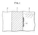
- porous member 1 is formed of a porous material which is permeable to gas only, that is, impermeable to melts, such as a molten metal, matte, and slag. If melt 2 is brought into contact with one side of porous member 1, and if the other side of member 1 is kept at a vacuum or at reduced pressure 3, the pressure on the wall surface in contact with the melt drops without regard to the static pressure of the melt.
- gas-forming ingredients can be removed from the melt on the basis of the principle described above, and brought the present invention to completion.
- the impurities in the melt may react with the ingredients of the porous member, to form gases, and then they may be removed through the porous member.
- porous member is an oxide (M X O Y )
- the impurities such as N, H, O, and S
- the valuable components are sucked and removed or recovered from the melt.
- porous member 1 Various materials may be used for porous member 1, including metal oxides or other metallic compounds (non-oxides) and mixtures thereof and metal, such as Al2O3, MgO, CaO, SiO2, FeO, Cr2O3, BN, Si3N4, etc.
- the material used should not react with the principal ingredient of melt 2 so that porous member 1 in contact with melt 2 can be prevented from erosion loss and melt 2 can be kept clean.
- porous member 1 In order to make porous member 1 permeable to gas only and impermeable to melts, its porosity is preferably restricted to 40% or less, and its diameter is preferably about 200 ⁇ m or less. The porosity and pore diameter are controlled according to the wettability of the porous member 1.
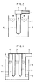
- Fig. 2 is in schematic sectional view showing a first embodiment of the invention.
- This embodiment is a batch-type vacuum degassing apparatus.
- Melt 2 is stored in vessel 5, and the lower half of degassing member 6 is immersed in melt 2.
- Degassing member 6 is in the form of a cylinder closed at the bottom, and its lower half immersed in melt 2 is formed of porous member 6a.
- Member 6a is formed of a porous material which, having fine pores, is permeable to gas, but is impermeable to melts, such as a molten metal, slag, and matte.
- the upper half of degassing member 6 is formed of nonporous member 6b which is impermeable to gas.
- Porous and nonporous members 6a and 6b may be joined together after being separately prepared.
- that portion of degassing member 6 which is to form nonporous member 6b may be made impermeable to gas by, for example, being coated with a gas- impermeable nonporous material, after the whole degassing member is formed from a porous material.
- a connecting member 7 is fixed to the upper end portion of gas-impermeable nonporous member 6b which is exposed to an atmosphere. Also, pipe 8, which is connected to a suitable vacuum-suction pump (not shown). is coupled to connecting member 7 so as to communicate with degassing member 6.
- Degassing member 9 comprises cylindrical housing 10, having a top wall, and bottomed cylindrical porous members 11 therein. Housing 10, which is open at the bottom end, is set so that its bottom opening portion is immersed in melt 2.
- Pipe 8 is connected to the top end of housing 10. The inside of housing 10 is evacuated or decompressed by suction through pipe 8 by means of a suitable vacuum pump (not shown).
- a plurality of porous members 11 are suspended from the top wall of housing 10.
- Members 11 are formed entirely of a porous material which is permeable to gas but is impermeable to melts.
- Hole 13 through which the gas passes is formed at the upper end portion of each porous member 11.
- each porous member 11 is brought into contact with melt 2. Then, the gas-forming ingredients in melt 2 are sucked and removed in the form of gases from the melt through porous member 11.
- melt 2 touches a very wide region of each porous member 11, so that the gas-forming ingredients can be removed from the melt with very high efficiency.
- a vacuum degassing apparatus according to a third embodiment of the present invention will be described.
- This embodiment is a continuous vacuum degassing apparatus.
- Cylindrical melt circulating pipe 15 penetrates a vacuum vessel 14.
- the inside of vessel 14, which is connected to a suitable vacuum pump (not shown), is kept at a vacuum.
- At least that part of circulating pipe 15 which is situated in vessel 14 is formed of a porous member which has the aforementioned properties.
- Melt 2 is allowed to circulate through pipe 15.
- melt 2 which is in contact with circulating pipe 15 is exposed to the vacuum through the porous circulating pipe when the melt circulates through pipe 15 and flows in vacuum vessel 14. While melt 2 is flowing in vessel 14, therefore, its gas-forming ingredients are sucked and removed. Thus, the gas-forming ingredients can be continuously removed from melt 2.
- Fig. 5A is a plan view showing a vacuum degassing apparatus according to this fourth embodiment
- Fig. 5B is a vertical sectional view of the apparatus.
- a plurality of planar dams 17 (three in number according to the example illustrated) are arranged parallel to one another at suitable intervals in open-topped box-shaped vessel 16.
- a plurality of melt passage holes 18 are bored through one end portion of each dam 17 in the thickness direction thereof, so as to be arranged in the height direction of dam 17.
- a plurality of gas suction holes 19 (five in number according to the example illustrated) are bored through each dam 17 in the height direction thereof, so as to be arranged in the width direction of dam 17.
- vessel 18 has inlet 20 and outlet 21 for melt 2.
- Dams are formed of a porous member having the aforementioned properties.
- melt 2 enters vessel 16 via inlet 20, and its course of circulation is regulated by means of dams 17.
- Melt 2 passes through melt passage holes 18 of dams 17 and circulates in zigzags in vessel 18, as indicated by arrows in the plan view of Fig. 5A.
- gas suction holes 19 of dams 17 are kept in a vacuum by suction through pipe 8, so that melt 2 is exposed to the vacuum through dams 17 while it is circulating through its course regulated by the dams.
- gas-forming ingredients are sucked and removed from melt 2.
- melt 2 can be continuously degassed, and the area of the porous member which touches the melt is wider than in the case of the embodiment shown in Fig. 4. Accordingly, the gas-forming ingredients can be removed from melt 2 with higher efficiency.
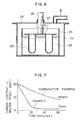
- Fig. 6 is a vertical sectional view showing a vacuum degassing apparatus according to a fifth embodiment of the invention.
- Vacuum vessel 22 is hermetically sealed by means of lid 23.
- Pipe 8 is connected to lid 23, and the inside of vacuum vessel 22 is kept at a vacuum by suction through pipe 8 by means of a suitable vacuum pump (not shown).
- Melt vessel 24 is disposed in vacuum vessel 22, and melt 2 is stored in vessel 24.
- a plurality of bottomed cylindrical porous members 25 are suspended from horizontal supporting plate 27.
- Supporting shaft 26 is fixed to the center of plate 27 so as to extend vertically to the outside through lid 23.
- Shaft 26 is rotated by means of a motor (not shown) which is located outside vacuum vessel 22. As shaft 26 rotates in this manner, porous members 25 move around shaft 26.
- melt 2 is loaded into melt vessel 24, porous member 25 is immersed in melt 2,and lid 23 is put on vacuum vessel 22, Thereafter, vessel 22 is evacuated through pipe 8. Then, member 25 is rotated by means of supporting shaft 26. Thereupon, melt 2 is exposed to the vacuum through porous member 25, and is stirred as member 25 rotates. Accordingly, melt 2 in vessel 24 is uniformly exposed to the vacuum, so that the gas-forming ingredients of melt 2 uniformly gasify on the surface of porous member 25, or uniformly react with member 25, thereby producing gases as reaction products. These gases are sucked and removed from melt 2 through porous member.
- degassing can be effected with very high efficiency.
- Fig. 7 is a graph comparatively showing the efficiencies for the respective cases of the embodiment using the porous pipe and the comparative example using no porous pipe.
- the axes of abscissa and ordinate represent the time and the carbon concentration of the molten iron.
- the present invention can be very effectively applied to the removal or recovery of gas-forming solute ingredients from melts.
- FIG. 8 A comparison between a case where non-porous porcelain pipe is used and a case where a porous pipe is used, both for decarburization of molten iron, is shown in Fig. 8. Also, a case, where a porous pipe is immersed with normal pressure in it, is shown for comparison.
- This graph shows that a decarburizing rate in a case where a non-porous porcelain pipe is used is almost the same as that in a case where a porous pipe is used with the inside of the pipe kept at normal pressure, which suggests that pressure reduction in a non-porous pipe gives almost no effect, and that, when pressure is reduced in a porous pipe, the decarburizing rate is largely increases. Note that the conditions for the testing, excluding composition of the immersion pipe, are the same as those in the previous experiment (see Fig. 7).
- a reaction rate constant on a surface of an immersion pipe can be obtained through the following equation.
- [ppm C] is the carbon content in the molten iron
- k is the reaction rate constant.
- A is the area of the reaction interface
- V is the volume of the molten iron
- t is time
- ppm C]0 indicates the initial carbon content
- subscripts C and t indicate the interface between the crucible and molten iron and the interface between the immersion pipe and molted iron, respectively.
- a mullite Al2O3:SiO2
- Al As mullite easily reacts and gets wet with Al, Al easily comes into minute holes, so that there is no way for use, but to use a non-porous porcelain pipe.
- a porous pipe is used to make use of the fact, when a material which hardly gets wet with molten material is used, the molten material does not come into minute holes, which is a feature of this method.
- a mechanism to remove generated gas in the locally depressurized dissolution method is based on diffusion because the pipe is non-porous, while a mechanism in the vacuum suction degassing method is based on vacuum suction, so the mechanism in these two methods are completely different.
Landscapes
- Chemical & Material Sciences (AREA)
- Engineering & Computer Science (AREA)
- Materials Engineering (AREA)
- Metallurgy (AREA)
- Organic Chemistry (AREA)
- Manufacturing & Machinery (AREA)
- Mechanical Engineering (AREA)
- Manufacture And Refinement Of Metals (AREA)
- Treatment Of Steel In Its Molten State (AREA)
- Degasification And Air Bubble Elimination (AREA)
Applications Claiming Priority (2)
| Application Number | Priority Date | Filing Date | Title |
|---|---|---|---|
| JP87772/90 | 1990-04-02 | ||
| JP2087772A JPH0830223B2 (ja) | 1990-04-02 | 1990-04-02 | 真空吸引式脱ガス方法及び装置 |
Publications (2)
| Publication Number | Publication Date |
|---|---|
| EP0450544A2 true EP0450544A2 (fr) | 1991-10-09 |
| EP0450544A3 EP0450544A3 (en) | 1992-05-06 |
Family
ID=13924268
Family Applications (1)
| Application Number | Title | Priority Date | Filing Date |
|---|---|---|---|
| EP19910105145 Withdrawn EP0450544A3 (en) | 1990-04-02 | 1991-04-02 | A vacuum-suction degassing method and an apparatus therefor |
Country Status (4)
| Country | Link |
|---|---|
| US (1) | US5167698A (fr) |
| EP (1) | EP0450544A3 (fr) |
| JP (1) | JPH0830223B2 (fr) |
| CA (1) | CA2039598C (fr) |
Cited By (1)
| Publication number | Priority date | Publication date | Assignee | Title |
|---|---|---|---|---|
| US5415680A (en) * | 1992-11-09 | 1995-05-16 | Eckert; C. Edward | Molten metal vacuum treatment and apparatus |
Families Citing this family (3)
| Publication number | Priority date | Publication date | Assignee | Title |
|---|---|---|---|---|
| US6484783B1 (en) | 2000-05-23 | 2002-11-26 | Thermwood Corporation | Workpiece holding apparatus and method thereof |
| US7526917B1 (en) * | 2008-08-11 | 2009-05-05 | Hoffman John C | Gas diffusion vacuum device |
| US9145597B2 (en) | 2013-02-22 | 2015-09-29 | Almex Usa Inc. | Simultaneous multi-mode gas activation degassing device for casting ultraclean high-purity metals and alloys |
Family Cites Families (7)
| Publication number | Priority date | Publication date | Assignee | Title |
|---|---|---|---|---|
| DE1051008B (de) * | 1959-02-19 | Aluminium-Industrie-Aktiengesellschaft, Chippis (Schweiz) | Verfahren und Vorrichtung zur Entgasung und zur Gasgehaltsbestimmung von Flüssigkeiten, insbesondere Metallschmelzen | |
| US2809107A (en) * | 1953-12-22 | 1957-10-08 | Aluminum Co Of America | Method of degassing molten metals |
| DE1032553B (de) * | 1955-08-09 | 1958-06-19 | Fischer Ag Georg | Verfahren zur Entgasung von fluessigen Schmelzen und Vorrichtung zur Durchfuehrung des Verfahrens |
| US2859262A (en) * | 1955-09-05 | 1958-11-04 | Hoerder Huettenunion Ag | Apparatus for degasifying liquid metal |
| DE2158866A1 (de) * | 1971-11-27 | 1973-05-30 | Engstfeld Wilh Fa | Vorrichtung zum entgasen von metallschmelzen |
| JPS5278602A (en) * | 1975-12-25 | 1977-07-02 | Toyota Motor Corp | Vacuum degassing of molten metal |
| JP2585622B2 (ja) * | 1987-08-27 | 1997-02-26 | 大塚工機株式会社 | 足踏み式パ−キングブレ−キ装置 |
-
1990
- 1990-04-02 JP JP2087772A patent/JPH0830223B2/ja not_active Expired - Lifetime
-
1991
- 1991-04-02 CA CA002039598A patent/CA2039598C/fr not_active Expired - Fee Related
- 1991-04-02 EP EP19910105145 patent/EP0450544A3/en not_active Withdrawn
- 1991-04-02 US US07/679,219 patent/US5167698A/en not_active Expired - Fee Related
Cited By (1)
| Publication number | Priority date | Publication date | Assignee | Title |
|---|---|---|---|---|
| US5415680A (en) * | 1992-11-09 | 1995-05-16 | Eckert; C. Edward | Molten metal vacuum treatment and apparatus |
Also Published As
| Publication number | Publication date |
|---|---|
| EP0450544A3 (en) | 1992-05-06 |
| JPH03287730A (ja) | 1991-12-18 |
| JPH0830223B2 (ja) | 1996-03-27 |
| US5167698A (en) | 1992-12-01 |
| CA2039598A1 (fr) | 1991-10-03 |
| CA2039598C (fr) | 1996-12-10 |
Similar Documents
| Publication | Publication Date | Title |
|---|---|---|
| US7682556B2 (en) | Degassing of molten alloys with the assistance of ultrasonic vibration | |
| US5037471A (en) | Method for manufacturing oxygen-free copper | |
| EP3470149A1 (fr) | Appareil et procédé de traitement de masse fondue | |
| US5167698A (en) | Vacuum-suction degassing method and an apparatus therefor | |
| EP0462536A1 (fr) | Procédé et appareil pour le dégazage par traitement sous vide | |
| EP0462537A1 (fr) | Appareil pour dégazer sous vide | |
| US5324487A (en) | Vacuum-suction degassing apparatus | |
| US4817918A (en) | Apparatus for filtering molten scraps of metal for regeneration | |
| US5346185A (en) | Vacuum-suction degassing apparatus | |
| EP0462538B1 (fr) | Dispositif de dégazage continu sous vide | |
| JP3654181B2 (ja) | 溶融金属の精錬方法 | |
| JPH0830226B2 (ja) | 真空吸引式脱ガス装置 | |
| Miyata et al. | Deoxidation of molten copper with a rotating graphite cylinder | |
| JPS61288008A (ja) | 二次精錬方法及び装置 | |
| GB2057904A (en) | Purifying molten copper | |
| JPH0830225B2 (ja) | 真空吸引式脱ガス方法 | |
| JP6459643B2 (ja) | 非金属介在物の除去方法および吸着体 | |
| JPS596313A (ja) | 溶鋼中介在物の除去方法 | |
| JPH06212244A (ja) | 極低窒素鋼の溶製方法 | |
| JP2000178636A (ja) | Rh真空脱ガス装置における清浄鋼の製造方法 | |
| JPH0753893B2 (ja) | 脱ガス方法及び装置 | |
| JPH0317235A (ja) | 溶融金属の小ロット真空精錬方法 | |
| JPH11269566A (ja) | 複合材溶湯の脱ガス撹拌装置 | |
| JPH02141520A (ja) | 溶鋼の清浄化方法 | |
| JPH06114502A (ja) | 鋳型付金属溶湯保持炉における溶湯保持法および鋳型付金属溶湯保持炉 |
Legal Events
| Date | Code | Title | Description |
|---|---|---|---|
| PUAI | Public reference made under article 153(3) epc to a published international application that has entered the european phase |
Free format text: ORIGINAL CODE: 0009012 |
|
| AK | Designated contracting states |
Kind code of ref document: A2 Designated state(s): AT DE ES FR GB IT |
|
| PUAL | Search report despatched |
Free format text: ORIGINAL CODE: 0009013 |
|
| AK | Designated contracting states |
Kind code of ref document: A3 Designated state(s): AT DE ES FR GB IT |
|
| 17P | Request for examination filed |
Effective date: 19920529 |
|
| 17Q | First examination report despatched |
Effective date: 19940228 |
|
| APAB | Appeal dossier modified |
Free format text: ORIGINAL CODE: EPIDOS NOAPE |
|
| APAD | Appeal reference recorded |
Free format text: ORIGINAL CODE: EPIDOS REFNE |
|
| APAB | Appeal dossier modified |
Free format text: ORIGINAL CODE: EPIDOS NOAPE |
|
| STAA | Information on the status of an ep patent application or granted ep patent |
Free format text: STATUS: THE APPLICATION HAS BEEN WITHDRAWN |
|
| 18W | Application withdrawn |
Withdrawal date: 19990618 |
|
| APAF | Appeal reference modified |
Free format text: ORIGINAL CODE: EPIDOSCREFNE |