EP0450806B1 - Détection et isolation de défauts dans un faisceau de câbles d'automobile - Google Patents
Détection et isolation de défauts dans un faisceau de câbles d'automobile Download PDFInfo
- Publication number
- EP0450806B1 EP0450806B1 EP91302433A EP91302433A EP0450806B1 EP 0450806 B1 EP0450806 B1 EP 0450806B1 EP 91302433 A EP91302433 A EP 91302433A EP 91302433 A EP91302433 A EP 91302433A EP 0450806 B1 EP0450806 B1 EP 0450806B1
- Authority
- EP
- European Patent Office
- Prior art keywords
- test line
- termination
- test
- connector
- dedicated
- Prior art date
- Legal status (The legal status is an assumption and is not a legal conclusion. Google has not performed a legal analysis and makes no representation as to the accuracy of the status listed.)
- Expired - Lifetime
Links
Images


Classifications
-
- G—PHYSICS
- G01—MEASURING; TESTING
- G01R—MEASURING ELECTRIC VARIABLES; MEASURING MAGNETIC VARIABLES
- G01R31/00—Arrangements for testing electric properties; Arrangements for locating electric faults; Arrangements for electrical testing characterised by what is being tested not provided for elsewhere
- G01R31/005—Testing of electric installations on transport means
- G01R31/006—Testing of electric installations on transport means on road vehicles, e.g. automobiles or trucks
-
- G—PHYSICS
- G01—MEASURING; TESTING
- G01R—MEASURING ELECTRIC VARIABLES; MEASURING MAGNETIC VARIABLES
- G01R31/00—Arrangements for testing electric properties; Arrangements for locating electric faults; Arrangements for electrical testing characterised by what is being tested not provided for elsewhere
- G01R31/08—Locating faults in cables, transmission lines, or networks
- G01R31/11—Locating faults in cables, transmission lines, or networks using pulse reflection methods
Definitions
- the present invention relates in general to the detection and isolation of interconnect faults in an automotive wiring system, and more specifically to the application of pulse signals to a dedicated test line included in the wiring harness and the monitoring of reflections of the pulse signals from impedances in the test line to determine the existence and/or location of improperly connected connectors.
- the electrical interconnect system of an automobile takes the form of a wiring harness which is normally partitioned into segments. Each segment includes a number of individual conductors. Individual segments are joined by electrical connectors at either end. Furthermore, an individual conductor or conductors may leave the main bundle of wires in a particular segment to form a subsegment which extends to another connector.
- the shape of the wiring system is irregular and cannot normally be classified as a star, ring or other regular configuration.
- point-to-point connections between the electrical system load devices interconnected in the wiring system normally include many connectors and conductor segments. These connectors include expansion connectors, termination connectors, and junction blocks.
- An expansion connector interconnects the partitioned segments of the wiring harness, i.e., expands the wiring harness.
- Termination connectors interconnect the electrical devices of the vehicle with the wiring harness system, i.e., at -terminations of the wiring harness segments. Thus, the electrical devices are referred to as termination devices.
- a junction block is a device for cross-connecting wiring harness segments, electrical system devices, individual wiring harness conductor wires, and other junction blocks.
- the conductors and connectors of the wiring harness system can be either electrical, optical, or both.
- Improperly connected or nonconnected connectors result in the partial or complete failure of an electrical device or devices connected to the electrical system. Failure of a critical electrical system component may cause the vehicle to quit (i.e., lose drivability) which often requires the vehicle to be towed in for service. Interconnect problems that may inadvertently be present include both complete failures to properly interconnect connectors and partial interconnect failures such as when connectors are not fully inserted to their snap-lock position. These interconnect problems may not become apparent until extended use of the electrical system causes damage to an improperly connected device or until vibrations cause a partially connected connector to separate.
- U.S. patent 4,689,551 discloses a wiring harness testing apparatus which tests for proper assembly of the wiring harness itself, i.e., before the prefabricated harness is installed into a vehicle and before the termination connectors of the harness are connected to the vehicle electrical components.
- the termination connectors of the harness must be plugged into the testing apparatus or to a special adapter for testing.
- Each wire in the harness being tested is connected at one end to a current source and at the other end to ground by switches in the testing apparatus that are connected to each wire. Since the testing apparatus must be connected to the termination connectors of the wiring harness, the tests are not possible after the wiring harness is connected into the vehicle electrical system.
- European patent application 164570 in the name of Goto et al, discloses a wiring harness checker wherein a checker connects to each termination connector of the wiring harness being tested.
- the checker is connected to the harness on a test table and checks the conduction of individual conductors in the harness in both or either direction.
- the checker is useful only for testing before final assembly since there is no ability to check the harness after it is connected to the electrical components in the vehicle.
- U.S. patent 4,271,388, issued to Schaling discloses another testing apparatus requiring direct connection of the tester to the conductors and connectors of the cable set being tested. Shift registers are connected to one end of each conductor or connector to be tested. Light emitting diodes and logic circuits connected to the other end of each conductor or connector monitors signals received from the shift registers and indicate the correct or incorrect assembly of the wiring harness itself. Thus, the tester is suitable for testing only before final assembly with the electrical system components of the vehicle.
- U.S. patent 3,718,859 discloses a test element in the form of a connector insert which allows monitoring of individual conductors while a wiring harness is interconnected and in operation.
- the test element plugs into and interconnects the pins of a pair of connectors.
- the test element includes terminals on its outer surface, each terminal being electrically connected to one of the connector pins and thus to one of the individual conductors of the wiring harness.
- the terminals may be contacted by a meter to monitor a signal on the corresponding individual conductor. Therefore, the individual conductor can only be tested when the corresponding electrical device is energised. Furthermore, the failure to monitor an expected signal from a conductor does not reveal the location or reason for the occurrence of the fault.
- an automotive electrical system comprising, the features of claim 1.
- test signal pulse As the test signal pulse travels down the test line, pulse energy is reflected back toward the first end when an increase in test line impedance is encountered (such as at an unconnected connector). The time between the application of the pules to the test line and any reflected signal is measured. The reception of a pulse indicates the present of a disconnected connector and the time at which the reflected signal appears indicates the location of the fault (except the pulse reflection from the actual end of the test line). Since the dedicated test line is not loaded by any vehicle devices, it is a high impedance line and is compatible with time-domain reflectometry techniques.
- the magnitude of reflection corresponding to a particular time delay can also be measured to indicate the state of a corresponding connector in the test line. Changes in this measurement over time can be used to detect any changes or deterioration in a connector.
- Figure 1 is a diagram representing a portion of an automotive electrical system including a wiring harness system and termination devices.
- Figure 2 is a diagram representing a portion of an automotive electrical system having a dedicated test line incorporated therein.
- Figure 3 is a diagram showing the addition of a dedicated test line to the electrical system shown in Figure 1.
- Figure 4 is a cross-sectional view of an expansion connector containing a dedicated test line according to the present invention.
- Figure 5 is a cross-sectional view of a termination connector containing a dedicated test line according to the present invention.
- Figure 6 is a plan view of a junction block containing a dedicated test line according to the present invention.
- Figure 7 is a diagram showing a test apparatus of the present invention connected to a dedicated test line.
- Figure 8 is a waveform diagram of a transmitted test pulse and received signal reflections.
- Figure 9 is a schematic diagram showing an embodiment of the test apparatus in greater detail.
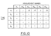
- Figure 10 is table showing the magnitude of reflected signal from a particular connector which changes over time.
- Figure 1 represents an automotive electrical system 20 including electrical system loads or supplies 21, 22, and 23, generally illustrative of various electrical components such as a radio, vehicle lighting, electric motors, or a voltage regulator. Since devices 21-23 are connected to the vehicle wiring harness through respective termination connectors 26-1, 26-2, and 26-3, each device is referred to as a termination device.
- a wiring harness interconnects devices 21-23 and other devices (not shown for clarity of the drawing).
- the wiring harness includes a plurality of harness segments each comprised of a wire bundle, some of which are indicated at 28. Segments 28 are interconnected using expansion connectors 25.
- Termination connectors 26 interconnect the wiring harness with the termination devices of the electrical system. For example, a termination connector 26-1 interconnects termination device 21 with the wiring harness.
- the wiring harness further includes a junction block 27 which connects through expansion connectors to harness segments 28 and which connects directly to some termination devices as shown. Segments 28 are shown as single lines although each contain a plurality of individual wires, some of which may leave the wire bundle at the several junction points.
- FIG. 2 represents a portion of an automotive electrical system 29 including a wiring harness 30 and a dedicated test line 31 according to the present invention.
- Dedicated test line 31 includes a first test point 32 connected to a first harness conductor 33 which enters wiring harness 30 and interconnects with an expansion connector 34.
- Dedicated test line 31 has corresponding connection pins mating in expansion connector 34 and continues with harness conductor 35.
- a termination connector 36 receives conductor 35 and provides a feed-through of the dedicated test line 31 to a harness conductor 37 when the termination device at termination connector 36 is properly interconnected. Harness conductor 37 feeds through another termination connector 38 only when its termination device is correctly interconnected.
- Dedicated test line 31 continues in a similar manner through a harness conductor 40, an expansion connector 41, a harness conductor 42, and a termination connector 43. After feeding through termination connector 43, dedicated test line 31 includes a harness conductor 44 extending to a second test point 45. Thus, there is a continuous electrical path from test point 32 to test point 45 only when each connector having dedicated test line 31 passing therethrough is properly interconnected.
- the proper interconnection of the electrical system can be tested by monitoring an electrical characteristic, such as continuity, of dedicated test line 31.
- an electrical characteristic such as continuity
- the portion of wiring harness 30 which includes dedicated test line 31 corresponds to the portions of the electrical system which are considered critical to operation of the vehicle and failure of which would cause the vehicle to quit or operate in an unacceptable manner.
- FIG. 3 illustrates the inclusion of a dedicated test line 55 into the electrical system of Figure 1.
- dedicated test line 55 may extend from a first test point 56 and through critical electrical system components, including expansion connector 25-6, termination connector 26-1, expansion connector 25-5, expansion connector 25-4, termination connector 26-3, expansion connector 25-3, termination connector 26-8, expansion connector 25-2, and expansion connector 25-1, to a second test point 57.
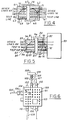
- FIG. 4 shows one embodiment of a pin and socket expansion connector useful in the present invention.
- An expansion connector 60 includes a first end 61 and a second end 62.
- First end 61 receives a test line harness conductor 63 which is connected to a terminal pin 64.
- Standard device lines 65 of the wiring harness are connected to terminal pins 66.
- Second end 62 is connected to a test line harness conductor 67 which is joined to a terminal socket 68.
- Device lines 70 are connected to terminal sockets 71. Insertion of expansion connector ends 61 and 62 results in interconnection of the corresponding pins and sockets.
- expansion connector ends 61 and 62 are interlocked by means of projections 72 and 73 on first end 61 being received by locking tabs 74 and 75 on second end 62.
- FIG. 5 shows a termination connector according to one embodiment of the present invention.
- a pin and socket termination connector 80 includes a first end 81 at the harness end of the connector and a second end 82 which is at the device end of the connector and which is integral with a termination device 83.
- a harness conductor 84 provides a dedicated test line into termination connector 80 and is connected to a terminal pin 86.
- a harness conductor 85 provides a dedicated test line out of termination connector 80 and is connected to a terminal pin 87.
- Device lines 88 from the wiring harness are connected to terminal pins 89.
- a terminal socket 90 and a terminal socket 91 in second connector end 82 are joined by a termination conductor 92 for feeding through the dedicated test line between harness conductors 84 and 85 when termination conductor 80 is properly interconnected.
- the connector is locked by means of projections 94 and 95 on first connector end 81 and locking tabs 96 and 97 on second connector end 82.
- FIG. 6 shows a junction block 100 which may be included in the electrical system of the present invention.
- Junction block 100 is comprised of an integral moulded block including conductors and interconnection points 101.
- Junction block 100 also includes a plurality of expansion connectors 102.
- termination devices 103 and 104 are connected directly to junction block 100.
- Junction block 100 further includes a dedicated test line 105 passing therethrough.
- Dedicated test line 105 is included in expansion connector 106 and passes into junction block 100.
- dedicated test line 105 passes into an expansion connector 107 and through termination connector 109 including a termination device 108.
- Dedicated test line 105 re-enters junction block 100 through expansion connector 107 and passes through termination device 104 before exiting junction block 100 through an expansion connector 110.
- a time-domain reflectometry fault detection and isolation system of the present invention is shown in Figure 7.
- a dedicated test line 115 extends between a first test point 116 and a test line termination 117. From test point 116, dedicated test line 115 enters a wiring harness 118 and passes through an expansion connector 120, a termination connector 121, a termination connector 124, an expansion connector 127, and a termination connector 130 in the manner previously described.
- a time-domain reflectometer 135 is connected to test point 116 through a test probe 136.
- a time-domain reflectometer is a known device which typically displays a test signal pulse and the time-delayed reflected components of the test signal on a time-calibrated oscilloscope. The magnitude of the reflected signal depends on the impedance of the dedicated test line at each successive point. Since the impedance of the dedicated test line is very low, except at the site of a disconnected connector, a significant reflected signal is received only from a disconnected connector or from the end of the dedicated test line if there are no unconnected connectors.
- Figure 8 shows a test pulse 140 occurring at a time t0 and having a voltage magnitude greater than a threshold voltage v th shown extending across the diagram at dashed line 141.
- the time-domain reflectometer After transmission of the test pulse signal, the time-domain reflectometer applies a time dependent gain to the signal received from the dedicated test line in order to compensate for the signal decay due to the impedance of the conductor line itself.
- variations in the received signal correspond substantially only to undesired impedances (e.g., discontinuities) in the dedicated test line.
- a reflected signal 142 is received at a time t1 which exceeds threshold voltage v th .
- a signal reflection 143 at a time t2, a signal reflection 144 at a time t3, and a signal reflection 145 at a time t4 correspond to the possible disconnection of other connectors that may be included in the dedicated test line.
- the complete disconnection of any single connector causes a zero received reflection from any subsequent connectors in the dedicated test line.
- each delay time t1 to t5 defines a respective time slot or range which is correlated with a respective connector.
- time-domain reflectometer 135 not employing an oscilloscope is shown in Figure 9.
- a microcontroller 150 is connected to a pulse generator 151 and to a receiver and comparator circuit 156.
- Microcontroller 150 is programmed to conduct test sequences and to analyse results of test sequences.
- Reflectometer 135 can be provided as a separate test device connected to the dedicated test line only during testing which is conducted after final assembly or during vehicle service.
- reflectometer 135 employing microcontroller 150 could be provided as a permanent part of a vehicle to provide testing during vehicle usage.
- Pulse generator 151 has an output connected to a series pair of resistors 152 and 153 connected to ground 154. Junction 155 between resistors 152 and 153 is connected to the dedicated test line and to an input of receiver and comparator circuit 156.
- pulse generator 151 To initiate a test sequence, pulse generator 151 generates a test pulse signal in response to a command signal from microcontroller 150.
- a test pulse signal travels from junction 155 down the dedicated test line and is reflected back to junction 155 by any discontinuities or jumps in test line impedance.
- Received signal reflections are time-gain amplified by receiver and comparator circuit 156 (i.e., the input signal from the test line is applied to an amplifier having a gain which increases with time to compensate for signal losses due to the increased distance travelled by later signals).
- the time-gain amplified signal is compared to a threshold voltage and the reception of a signal reflection greater than the threshold voltage is indicated to microcontroller 150.
- the time delay between the generation of the test pulse signal and the reception of a reflection having a magnitude greater than the threshold voltage is measured by microcontroller 150 and compared to the known time ranges corresponding to each respective connector or end of the dedicated test line.
- a signal reflection corresponding to a disconnected connector causes microcontroller 150 to indicate a fault by illuminating a warning light, for example.
- the identity of the failed connector can also be displayed and/or stored for later retrieval.
- receiver and comparator 156 continuously monitors the magnitude of the received signal reflection, that magnitude being further provided in a digital format to microcontroller 150.
- microcontroller 150 is able to estimate the impedance occurring at any point along the dedicated test line by determining the magnitude of signal reflection at a particular delay time.
- microcontroller 150 can determine any changes in impedance of the dedicated test line corresponding to the particular connector.
- any degradation in the connection at the particular connector can be sensed. It is thus possible to provide a warning of an impending failure of a connector before complete failure occurs.
- a plurality of time-separated measurements can be made corresponding to discrete time slots centred around delay times t1 to t5 which each correspond to particular connectors in the dedicated test line.
- a measurement m1 is conducted and the received magnitude of signal reflection at time t1 is .1 in arbitrary units.
- a measurement m2 is taken which indicates that there has been no change in the impedance at the corresponding connector.
- measurements m3 to m6 indicate an increase in the dedicated test line impedance in the area of the connector under test.
- time-domain reflectometer of the present invention has been described primarily in terms of an electrical test line, it is possible to utilise an optical test line in a similar manner.
- Light pulses generated by a light emitting diode would be reflected at discontinuities or disconnects in the test line. Reflections could be converted to electrical signals by an optical sensor, such as a photoconductive cell or a phototransistor.
Landscapes
- Physics & Mathematics (AREA)
- General Physics & Mathematics (AREA)
- Chemical & Material Sciences (AREA)
- Engineering & Computer Science (AREA)
- Combustion & Propulsion (AREA)
- Testing Of Short-Circuits, Discontinuities, Leakage, Or Incorrect Line Connections (AREA)
Claims (10)
- Système électrique de véhicule automobile, comprenant:une pluralité de composants électriques (21, 22, 23) comportant au moins un dispositif terminal;un système de harnais interconnectant ces composants électriques (21, 22, 23) et comportant une pluralité de conducteurs de harnais et une pluralité de connecteurs (25, 26), l'un de ces connecteurs (26-1) étant un connecteur terminal raccordé au dispositif terminal;
caractérisé en ce que:(1) le système de harnais comporte une ligne de test (31, 55) spécialement prévue pour des tests et formée par un conducteur terminal disposé dans le connecteur terminal (26-1) ainsi que par plusieurs conducteurs du harnais, la ligne de test s'étendant entré un point de test (32, 56) et une terminaison de ligne de test (45, 57) et formant un circuit électrique continu à partir du point de test (32, 56) jusqu'à la terminaison (45, 57) de la ligne lorsque chaque connecteur traversé de la ligne de test (31, 55) est convenablement raccordé;(2) un moyen d'attaque (135, 151) relié au point de test (32, 56, 116) et servant à appliquer une impulsion représentant un signal de test à la ligne de test (31, 55, 115) au point de test (32, 56, 116);(3) un moyen de réception (156) relié au point de test (32, 56, 116) et servant à détecter un signal résultant, retardé dans le temps, au point de test (32, 56, 116) en réponse au signal de test; et(4) un moyen de mesure de temps relié au moyen d'attaque (135, 151) et au moyen de réception pour mesurer le temps entre l'application de l'impulsion représentant le signal de test et la réception du signal résultat sous la forme d'une réflexion de l'impulsion. - Système électrique selon la revendication 1, caractérisé en outre en ce que la ligne de test (31, 55) est composée de conducteurs électriques du harnais et l'impulsion représentant le signal de test est un signal électrique.
- Système électrique selon la revendication 1, caractérisé en outre en ce que la ligne de test (31, 55) est composée de conducteurs optiques du harnais et l'impulsion représentative du signal de test est un signal optique.
- Système électrique selon l'une quelconque des revendications 1 à 3, caractérisé en outre par un moyen de mesure de signal relié au moyen d'attaque et au moyen de réception pour mesurer la grandeur d'un signal réfléchi pendant une période de temps déterminée par le moyen de mesure de temps et correspondant à l'impédance de la ligne de test (31, 55) à l'emplacement d'un des connecteurs (25, 26).
- Procédé pour isoler un défaut d'interconnexion dans un système électrique d'un véhicule automobile, procédé qui comprend les étapes consistant à:mettre à disposition une pluralité de composants électriques (21, 22, 23) comportant au moins un dispositif terminal et àinterconnecter ces composants électriques en utilisant un système de harnais comportant une pluralité de conducteurs de harnais et une pluralité de connecteurs (25, 26), l'un de ces connecteurs (26-1) étant un connecteur terminal raccordé au dispositif terminal,
caractérisé en ce qu'il comprend en outre les étapes consistant à:(1) mettre à disposition une ligne de test (31, 55) spécialement prévue à des fins de test à l'intérieur du système de harnais, ligne de test qui comporte un conducteur terminal disposé dans le connecteur terminal (26-1), la ligne de test (31, 55) comportant en outre plusieurs conducteurs du harnais;(2) mettre à disposition un point de test (32, 56) à une extrémité de la ligne de test et une terminaison de ligne de test (45, 57) à l'extrémité opposée de cette ligne, la ligne de test (31, 55) formant un circuit électrique continu à partir du point de test (32, 56) jusqu'à la terminaison (45, 55) de la ligne lorsque chaque connecteur (25, 26) traversé de la ligne de test (31, 55) est raccordé convenablement;(3) injecter une impulsion représentant un signal de test au point de test; et(4) mesurer le temps de retard entre l'injection de l'impulsion représentant le signal de test et l'arrivée au point de test d'une réflexion de cette impulsion, réflexion qui correspond à un défaut d'interconnexion ou à la terminaison de la ligne de test. - Procédé selon la revendication 5, caractérisé en outre en ce que la ligne de test (31, 55) est composée de conducteurs électriques, l'impulsion représentant le signal de test étant une impulsion électrique.
- Procédé selon la revendication 5, caractérisé en outre en ce que la ligne de test (31, 55) est composée de conducteurs optiques, l'impulsion représentant le signal de test étant une impulsion optique.
- Procédé selon la revendication 5, caractérisé en outre en ce que la ligne de test (31, 55) suit un trajet contenant des connecteurs terminaux (26-1, 26-2, 26-3) pour une pluralité de composants électriques critiques (21, 22, 23) du système électrique.
- Procédé selon la revendication 5, caractérisé en outre en ce qu'il comprend l'étape consistant à comparer le retard mesuré avec des retards connus correspondant chacun à un connecteur du système électrique afin de localiser un défaut.
- Procédé selon la revendication 5, caractérisé en outre par les étapes consistant à:répéter les étapes d'injection et de mesure à un moment ultérieur;comparer les résultats des étapes de mesure effectuées à différents moments; etprédire une défaillance du système électrique à la constatation de résultats inégaux lors des étapes de comparaison.
Applications Claiming Priority (2)
| Application Number | Priority Date | Filing Date | Title |
|---|---|---|---|
| US504451 | 1990-04-03 | ||
| US07/504,451 US5268644A (en) | 1990-04-03 | 1990-04-03 | Fault detection and isolation in automotive wiring harness by time-domain reflectometry |
Publications (3)
| Publication Number | Publication Date |
|---|---|
| EP0450806A2 EP0450806A2 (fr) | 1991-10-09 |
| EP0450806A3 EP0450806A3 (en) | 1991-10-30 |
| EP0450806B1 true EP0450806B1 (fr) | 1996-01-31 |
Family
ID=24006320
Family Applications (1)
| Application Number | Title | Priority Date | Filing Date |
|---|---|---|---|
| EP91302433A Expired - Lifetime EP0450806B1 (fr) | 1990-04-03 | 1991-03-20 | Détection et isolation de défauts dans un faisceau de câbles d'automobile |
Country Status (3)
| Country | Link |
|---|---|
| US (1) | US5268644A (fr) |
| EP (1) | EP0450806B1 (fr) |
| DE (1) | DE69116714T2 (fr) |
Families Citing this family (38)
| Publication number | Priority date | Publication date | Assignee | Title |
|---|---|---|---|---|
| JP3509943B2 (ja) * | 1994-07-20 | 2004-03-22 | 株式会社アドバンテスト | 伝送経路の伝播遅延時間測定回路 |
| US5530360A (en) * | 1994-12-09 | 1996-06-25 | Chrysler Corporation | Apparatus and method for diagnosing faults in a vehicle electrical system |
| JP3397957B2 (ja) * | 1996-01-10 | 2003-04-21 | 株式会社オートネットワーク技術研究所 | ワイヤーハーネスの故障位置検出方法及び同方法に用いるワイヤーハーネス |
| JP3234861B2 (ja) * | 1996-06-13 | 2001-12-04 | 株式会社日立製作所 | 乗物の電源供給装置及び集約配線装置 |
| US6163082A (en) * | 1996-06-13 | 2000-12-19 | Hitachi, Ltd. | Power supplying apparatus for a vehicle and an intensive wiring apparatus |
| US6037779A (en) * | 1997-09-17 | 2000-03-14 | Chrysler Corporation | Bus isolation/diagnostic tool |
| US6160405A (en) * | 1998-03-30 | 2000-12-12 | Jovial Test Equipment, Inc. | Method and apparatus for remotely changing signal characteristics of a signal generator |
| US6079259A (en) * | 1998-05-05 | 2000-06-27 | Caterpillar, Inc. | Apparatus and method for a diagnostic check of the electrical wiring of an internal combustion engine electronic unit injector system |
| GB9818791D0 (en) | 1998-08-28 | 1998-10-21 | Sun Electric Uk Ltd | Method and apparatus for automotive and other testing |
| GB2344239A (en) * | 1998-11-24 | 2000-05-31 | Edgcumbe Instr Limited | Pulse-echo location of faults in electric cables |
| US6612172B2 (en) * | 2001-03-05 | 2003-09-02 | Lucent Technologies Inc. | Sol-gel tube crack detection apparatus and method |
| TW567321B (en) | 2002-07-02 | 2003-12-21 | Via Tech Inc | Method of using waveform to judge position of connection failure |
| US6833713B2 (en) * | 2003-01-31 | 2004-12-21 | Delphi Technologies, Inc. | Smart wire harness for an electrical circuit |
| US20040168008A1 (en) * | 2003-02-18 | 2004-08-26 | Hewlett-Packard Development Company, L.P. | High speed multiple ported bus interface port state identification system |
| US7075310B2 (en) * | 2004-06-09 | 2006-07-11 | General Electric Company | Device and method for testing for a wiring fault condition |
| US7719992B1 (en) * | 2004-07-14 | 2010-05-18 | Cisco Tchnology, Ink. | System for proactive time domain reflectometry |
| US7368919B2 (en) * | 2004-09-02 | 2008-05-06 | Ziota Technology Inc. | Wireless portable automated harness scanner system and method therefor |
| US7525319B1 (en) * | 2008-08-28 | 2009-04-28 | International Business Machines Corporation | Method and apparatus to electrically qualify high speed PCB connectors |
| US20100262391A1 (en) * | 2008-11-05 | 2010-10-14 | Airbus Operations Gmbh | Device for testing a plug-in connection |
| US8164433B2 (en) * | 2009-04-17 | 2012-04-24 | Ac Propulsion, Inc. | Detecting faults in a wiring harness |
| US9330812B2 (en) * | 2009-05-28 | 2016-05-03 | Alliance Wireless Technologies, Inc. | Method and apparatus for communicating between cab interior and exterior chassis of truck |
| JP5550455B2 (ja) * | 2010-05-28 | 2014-07-16 | 矢崎総業株式会社 | ワイヤハーネス導通検査方法およびワイヤハーネス導通検査プログラム |
| EP2434591A3 (fr) * | 2010-09-28 | 2012-05-02 | Tyco Electronics France SAS | Connecteur électrique protégé contre la corrosion |
| US20130221974A1 (en) * | 2012-02-29 | 2013-08-29 | GM Global Technology Operations LLC | Time domain reflectometry system and method |
| CA2900994C (fr) * | 2013-02-12 | 2024-01-23 | Headsight, Inc. | Systeme diagnostique pour dispositif de commande |
| WO2016105486A1 (fr) * | 2014-12-23 | 2016-06-30 | Cooper Technologies Company | Test et surveillance d'une connexion électrique |
| US10704827B2 (en) | 2015-12-28 | 2020-07-07 | Eaton Intelligent Power Limited | Systems and methods for testing electrical connectors |
| US10520529B2 (en) | 2016-03-23 | 2019-12-31 | Cooper Technologies Company | Adapters for testing electrical equipment |
| WO2018060678A1 (fr) * | 2016-09-30 | 2018-04-05 | Bae Systems Plc | Système d'alimentation électrique |
| FR3066825B1 (fr) * | 2017-05-29 | 2019-07-19 | Dcns | Systeme de reflectometrie pour la detection de defaut sur un connecteur multipoints durci d'un reseau electrique |
| US10718660B2 (en) | 2017-06-13 | 2020-07-21 | Robert Bosch Gmbh | Closure detection system |
| US10732215B2 (en) | 2017-12-21 | 2020-08-04 | Mediatek Singapore Pte. Ltd. | Systems and methods for on-chip time-domain reflectometry |
| US11221379B2 (en) | 2017-12-21 | 2022-01-11 | Mediatek Singapore Pte. Ltd. | Systems and methods for on-chip time-domain reflectometry |
| DE102018214326A1 (de) * | 2018-08-24 | 2020-02-27 | Airbus Operations Gmbh | Kabelbaumtestsystem und Testverfahren zum Überprüfen von Kabelbäumen |
| US12572643B2 (en) | 2022-08-22 | 2026-03-10 | Nxp B.V. | Circuit and method for detecting a fault injection attack in an integrated circuit |
| DE102022129688A1 (de) | 2022-11-10 | 2024-05-16 | Bayerische Motoren Werke Aktiengesellschaft | Fahrzeug mit Stromverteiler mit TDR-Messeinrichtung |
| KR102864726B1 (ko) * | 2023-03-24 | 2025-09-25 | 국립군산대학교산학협력단 | 차량용 하네스 검사 장치 |
| CN119805079B (zh) * | 2025-03-12 | 2025-08-08 | 湖南众连线束股份有限公司 | 多线束测试方法及系统 |
Citations (1)
| Publication number | Priority date | Publication date | Assignee | Title |
|---|---|---|---|---|
| US3718859A (en) * | 1971-02-01 | 1973-02-27 | Us Army | Electric circuit test element for use with a pair of electrical connectors |
Family Cites Families (30)
| Publication number | Priority date | Publication date | Assignee | Title |
|---|---|---|---|---|
| DE1219585B (de) * | 1961-12-20 | 1966-06-23 | Siemens Ag | Anordnung zum Ermitteln von Fehler- oder Inhomogenitaetsstellen elektrischer Leitungen |
| US3607535A (en) * | 1968-11-29 | 1971-09-21 | Book Covers | Apparatus and method for making and coating book cover board structures |
| GB1352124A (en) * | 1970-07-08 | 1974-05-08 | Electricity Council | Cable fault location |
| US3699438A (en) * | 1970-08-21 | 1972-10-17 | Honeywell Inf Systems | Apparatus to visually identify and test wires in a multi-wire cable |
| US3728616A (en) * | 1971-02-02 | 1973-04-17 | Western Electric Co | Continuity testing apparatus utilizing a plurality of paired resistors |
| US3750012A (en) * | 1972-01-01 | 1973-07-31 | Bell Telephone Labor Inc | Cating system for waveguide transmission line utilizing spaced reflectors |
| US4042832A (en) * | 1975-12-29 | 1977-08-16 | Honeywell Information Systems Inc. | Logic board interlock indication apparatus |
| DE2723536C3 (de) * | 1977-05-25 | 1980-10-23 | Daimler-Benz Ag, 7000 Stuttgart | Vorrichtung zum Prüfen verschiedenartiger Kabelsätze |
| GB2017432A (en) * | 1978-03-28 | 1979-10-03 | Lucas Industries Ltd | Motor vehicle electrical system |
| US4218745A (en) * | 1978-09-11 | 1980-08-19 | Lockheed Corporation | Microcomputer assisted electrical harness fabrication and testing system |
| US4257002A (en) * | 1978-12-11 | 1981-03-17 | Thomas & Betts Corporation | Automatic harness tester |
| US4322677A (en) * | 1979-03-16 | 1982-03-30 | Minnesota Mining And Manufacturing Company | System and method for locating resistive faults and interconnect errors in multi-conductor cables |
| EP0039122A3 (fr) * | 1980-03-04 | 1982-01-27 | Thomas Electronics Limited | Appareil et méthode pour tester des systèmes électriques d'un véhicule |
| US4399400A (en) * | 1980-10-30 | 1983-08-16 | Cablescan, Inc. | Apparatus for testing multiconductor cables and having transition circuit means for extending its capability |
| DE3115200A1 (de) * | 1981-04-15 | 1983-02-03 | Philips Kommunikations Industrie AG, 8500 Nürnberg | Verfahren zur messung von impulslaufzeiten, fehlerorten und daempfung auf kabeln und lichtwellenleitern |
| US4404514A (en) * | 1981-08-24 | 1983-09-13 | General Instrument Corporation | Fault detection system as for locating faulty connections in a cable television system |
| US4538103A (en) * | 1982-08-30 | 1985-08-27 | John Cappon | Time domain reflectometer apparatus for identifying the location of cable defects |
| EP0164570A3 (fr) * | 1984-05-11 | 1987-01-07 | Sumitomo Wiring Systems, Ltd. | Appareil d'essai pour mesurer la conductivité d'un harnais de câbles |
| US4689551A (en) * | 1985-09-05 | 1987-08-25 | Tektite Corporation | Testing wiring harnesses |
| JPS6264082A (ja) * | 1985-09-17 | 1987-03-20 | 日産自動車株式会社 | コネクタ嵌合確認装置 |
| DE3533479A1 (de) * | 1985-09-19 | 1987-03-26 | Seba Mess Ortungstech | Verfahren zum ueberwachen eines objektes mit hilfe einer signalleitung sowie impuls-messgeraet zur durchfuehrung dieses verfahrens |
| US4766386A (en) * | 1986-05-23 | 1988-08-23 | Cabletron | Time domain reflectometer for measuring impedance discontinuities on a powered transmission line |
| DE3713262A1 (de) * | 1987-04-18 | 1988-11-03 | Heidelberger Druckmasch Ag | Steckverbindungs-codierung fuer elektrische kabel |
| US4812752A (en) * | 1987-10-19 | 1989-03-14 | Allied-Signal Inc. | Open finder |
| US4859953A (en) * | 1988-07-08 | 1989-08-22 | General Motors Corporation | Modular test assembly for wiring harnesses |
| US4949076A (en) * | 1988-10-13 | 1990-08-14 | Conoco Inc. | Apparatus for detecting and locating leakage in underwater structures |
| DE3838657A1 (de) * | 1988-11-15 | 1990-05-17 | Bayerische Motoren Werke Ag | Einrichtung zur erkennung des unbeabsichtigten loesens der beiden steckerteile eines elektrischen verbindungssteckers |
| JPH082940Y2 (ja) * | 1988-11-25 | 1996-01-29 | 富士重工業株式会社 | 車両用電気系統コネクタ監視装置 |
| US4998069A (en) * | 1989-03-31 | 1991-03-05 | Tandem Computers Incorporated | Loopback tester for testing field replaceable units |
| US5066919A (en) * | 1990-04-03 | 1991-11-19 | Ford Motor Company | Fault detection and isolation in automotive wiring harness by network analysis method |
-
1990
- 1990-04-03 US US07/504,451 patent/US5268644A/en not_active Expired - Fee Related
-
1991
- 1991-03-20 DE DE69116714T patent/DE69116714T2/de not_active Expired - Lifetime
- 1991-03-20 EP EP91302433A patent/EP0450806B1/fr not_active Expired - Lifetime
Patent Citations (1)
| Publication number | Priority date | Publication date | Assignee | Title |
|---|---|---|---|---|
| US3718859A (en) * | 1971-02-01 | 1973-02-27 | Us Army | Electric circuit test element for use with a pair of electrical connectors |
Also Published As
| Publication number | Publication date |
|---|---|
| EP0450806A2 (fr) | 1991-10-09 |
| DE69116714T2 (de) | 1996-05-30 |
| EP0450806A3 (en) | 1991-10-30 |
| US5268644A (en) | 1993-12-07 |
| DE69116714D1 (de) | 1996-03-14 |
Similar Documents
| Publication | Publication Date | Title |
|---|---|---|
| US5268644A (en) | Fault detection and isolation in automotive wiring harness by time-domain reflectometry | |
| US5066919A (en) | Fault detection and isolation in automotive wiring harness by network analysis method | |
| US6803770B2 (en) | Wireless multiconductor cable test system and method | |
| US5264796A (en) | Fault detection and isolation in automotive wiring harness including dedicated test line | |
| US9250283B2 (en) | System and method for automated testing of an electric cable harness | |
| US5414343A (en) | Permanently installed cable system with integrated multi-cable tester | |
| US6160405A (en) | Method and apparatus for remotely changing signal characteristics of a signal generator | |
| US5903156A (en) | Method for detecting trouble location in wire harnesses and wire harness to be used in the method | |
| US20070001683A1 (en) | System for testing wiring characteristics | |
| US6859041B2 (en) | Methods for locating faults in aircraft branch conductors and determining the distance to the faults | |
| CN1239914C (zh) | 线缆故障监测系统 | |
| CN111965563A (zh) | 排线检测装置 | |
| US4651084A (en) | Fault test apparatus for conductors of multiconductor cable | |
| KR100310971B1 (ko) | 와이어 하네스 시험방법 및 이를 수행하기 위한 시스템 | |
| EP0144496A1 (fr) | Méthode et appareil pour tester des défauts de câblage dans un réseau | |
| CA1220521A (fr) | Methode diagnostique des defectuosites d'un systeme electronique d'alimentation en carburant | |
| KR20210133091A (ko) | 와이어 하네스 시험방법 및 이를 수행하기 위한 시스템 | |
| CN112904256B (zh) | 一种自动测试机的线路自检方法 | |
| US11486921B2 (en) | Protection adapter for oscilloscope probes | |
| US6037779A (en) | Bus isolation/diagnostic tool | |
| KR102857123B1 (ko) | 테스트용 와이어 하네스 검사장치 및 방법 | |
| JPS6317015Y2 (fr) | ||
| JP3605228B2 (ja) | Patコネクタテスター及びその終端回路網 | |
| KR100396846B1 (ko) | 자동차 고장진단을 위한 다채널 진단장비의상대전압측정에 의한 접속 이상유무의 판단방법 | |
| JPH05180892A (ja) | 複数導線の導通検査方法および装置 |
Legal Events
| Date | Code | Title | Description |
|---|---|---|---|
| PUAI | Public reference made under article 153(3) epc to a published international application that has entered the european phase |
Free format text: ORIGINAL CODE: 0009012 |
|
| PUAL | Search report despatched |
Free format text: ORIGINAL CODE: 0009013 |
|
| AK | Designated contracting states |
Kind code of ref document: A2 Designated state(s): DE FR GB |
|
| AK | Designated contracting states |
Kind code of ref document: A3 Designated state(s): DE FR GB |
|
| 17P | Request for examination filed |
Effective date: 19920331 |
|
| 17Q | First examination report despatched |
Effective date: 19940203 |
|
| GRAA | (expected) grant |
Free format text: ORIGINAL CODE: 0009210 |
|
| AK | Designated contracting states |
Kind code of ref document: B1 Designated state(s): DE FR GB |
|
| PGFP | Annual fee paid to national office [announced via postgrant information from national office to epo] |
Ref country code: GB Payment date: 19960229 Year of fee payment: 6 Ref country code: FR Payment date: 19960229 Year of fee payment: 6 |
|
| REF | Corresponds to: |
Ref document number: 69116714 Country of ref document: DE Date of ref document: 19960314 |
|
| ET | Fr: translation filed | ||
| PGFP | Annual fee paid to national office [announced via postgrant information from national office to epo] |
Ref country code: DE Payment date: 19960315 Year of fee payment: 6 |
|
| PLBE | No opposition filed within time limit |
Free format text: ORIGINAL CODE: 0009261 |
|
| STAA | Information on the status of an ep patent application or granted ep patent |
Free format text: STATUS: NO OPPOSITION FILED WITHIN TIME LIMIT |
|
| PG25 | Lapsed in a contracting state [announced via postgrant information from national office to epo] |
Ref country code: DE Effective date: 19961217 |
|
| 26N | No opposition filed | ||
| PG25 | Lapsed in a contracting state [announced via postgrant information from national office to epo] |
Ref country code: GB Effective date: 19970320 |
|
| GBPC | Gb: european patent ceased through non-payment of renewal fee |
Effective date: 19970320 |
|
| PG25 | Lapsed in a contracting state [announced via postgrant information from national office to epo] |
Ref country code: FR Free format text: LAPSE BECAUSE OF NON-PAYMENT OF DUE FEES Effective date: 19971128 |
|
| REG | Reference to a national code |
Ref country code: FR Ref legal event code: ST |