EP0450933B1 - Magnetoresistiver Druckaufnehmer - Google Patents
Magnetoresistiver Druckaufnehmer Download PDFInfo
- Publication number
- EP0450933B1 EP0450933B1 EP91302919A EP91302919A EP0450933B1 EP 0450933 B1 EP0450933 B1 EP 0450933B1 EP 91302919 A EP91302919 A EP 91302919A EP 91302919 A EP91302919 A EP 91302919A EP 0450933 B1 EP0450933 B1 EP 0450933B1
- Authority
- EP
- European Patent Office
- Prior art keywords
- pressure
- deforming part
- pressure sensor
- magnetic alloy
- amorphous magnetic
- Prior art date
- Legal status (The legal status is an assumption and is not a legal conclusion. Google has not performed a legal analysis and makes no representation as to the accuracy of the status listed.)
- Expired - Lifetime
Links
Images




Classifications
-
- G—PHYSICS
- G01—MEASURING; TESTING
- G01L—MEASURING FORCE, STRESS, TORQUE, WORK, MECHANICAL POWER, MECHANICAL EFFICIENCY, OR FLUID PRESSURE
- G01L9/00—Measuring steady of quasi-steady pressure of fluid or fluent solid material by electric or magnetic pressure-sensitive elements; Transmitting or indicating the displacement of mechanical pressure-sensitive elements, used to measure the steady or quasi-steady pressure of a fluid or fluent solid material, by electric or magnetic means
- G01L9/10—Measuring steady of quasi-steady pressure of fluid or fluent solid material by electric or magnetic pressure-sensitive elements; Transmitting or indicating the displacement of mechanical pressure-sensitive elements, used to measure the steady or quasi-steady pressure of a fluid or fluent solid material, by electric or magnetic means by making use of variations in inductance, i.e. electric circuits therefor
-
- G—PHYSICS
- G01—MEASURING; TESTING
- G01L—MEASURING FORCE, STRESS, TORQUE, WORK, MECHANICAL POWER, MECHANICAL EFFICIENCY, OR FLUID PRESSURE
- G01L9/00—Measuring steady of quasi-steady pressure of fluid or fluent solid material by electric or magnetic pressure-sensitive elements; Transmitting or indicating the displacement of mechanical pressure-sensitive elements, used to measure the steady or quasi-steady pressure of a fluid or fluent solid material, by electric or magnetic means
- G01L9/16—Measuring steady of quasi-steady pressure of fluid or fluent solid material by electric or magnetic pressure-sensitive elements; Transmitting or indicating the displacement of mechanical pressure-sensitive elements, used to measure the steady or quasi-steady pressure of a fluid or fluent solid material, by electric or magnetic means by making use of variations in the magnetic properties of material resulting from the application of stress
-
- Y—GENERAL TAGGING OF NEW TECHNOLOGICAL DEVELOPMENTS; GENERAL TAGGING OF CROSS-SECTIONAL TECHNOLOGIES SPANNING OVER SEVERAL SECTIONS OF THE IPC; TECHNICAL SUBJECTS COVERED BY FORMER USPC CROSS-REFERENCE ART COLLECTIONS [XRACs] AND DIGESTS
- Y10—TECHNICAL SUBJECTS COVERED BY FORMER USPC
- Y10S—TECHNICAL SUBJECTS COVERED BY FORMER USPC CROSS-REFERENCE ART COLLECTIONS [XRACs] AND DIGESTS
- Y10S73/00—Measuring and testing
- Y10S73/02—Magnetostrictive
Definitions
- This invention relates to a pressure sensor utilizing a magnetostriction effect of an amorphous magnetic alloy.
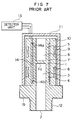
- Fig. 7 is a schematic vertical cross-sectional view of one example of such pressure sensor.
- This pressure sensor comprises a cylindrical base or body 1 made of titanium, a film 7 of an amorphous magnetic alloy mounted around the outer periphery of the body 1, a cylindrical tubular bobbin 10 disposed radially outwardly of the film 7 and mounted around the outer periphery of the body 1, a pressure detector coil 8 wound on the outer periphery of the bobbin 10, a dummy coil 9 wound on the outer periphery of the bobbin 10, a cup-shaped yoke 11 mounted radially outwardly of the two coils 8 and 9, and a detector unit 13 electrically connected to the two coils 8 and 9.
- the body 1 has two central holes separated from each other by a partition wall la, the two central holes defining a pressure chamber 3 and a dummy chamber (or reference chamber) 6, respectively.
- the body 1 also has a pressure introducing opening 2 defined by an open end of the pressure chamber 3, a greater-diameter flange 1b formed on the outer periphery of the body 1 and disposed adjacent to the end of the body 1 having a pressure introducing opening 2, a recess (smallest-diameter portion) 14 formed in the outer periphery of the body 1 and extending throughout the entire length of the smaller-diameter portion of the body 1 between the end portion (the upper end portion is Fig.
- a wall part which defines part of the pressure chamber 3 and exists between the pressure chamber 3 and the recess 14 is a deforming part 4 which is deformed in response to a change in the pressure within the pressure chamber 3.
- Another wall part, being integrated with the above-mentioned wall, which defines part of the dummy chamber 6 and exists between the dummy chamber 6 and the recess 14 is a non-deforming part 5 which is not influenced by the pressure in the chamber 3.
- the film 7 which is a rectangular thin sheet of an amorphous magnetic alloy is disposed in the recess 14, and is wound around the outer periphery of the body 1, and is fixedly bonded thereto by an adhesive under pressure.
- the depth of the recess 14, that is, the height of steps 14a and 14b, is determined to be equal to the sum of the thickness of the wound film 7 and the thickness of the adhesive layer.
- the fixed bonding of the film 7 by application of pressure is carried out by fitting a tube 21 of a heat-shrinkable resin on the film 7 and then by heating this tube (see Figs. 8a to 8c). After this bonding operation, the tube is removed.
- the steps 14a and 14b serve as positioning means which prevents the film 7 from being displaced along the axis of the body 1 during the fixed bonding of the film 7 by the adhesive.
- the bobbin 10 having two peripheral grooves in its outer peripheral surface covers the recess 14, and is fitted on the body 1.
- the pressure detector coil 8 is received in one of the two peripheral grooves close to the flange 1b, and the dummy coil 9 is received in the other peripheral groove.
- the two coils 8 and 9 are used as permeability detector elements, and cooperate with the amorphous magnetic alloy film 7 to form a magnetic circuit.
- the pressure of a fluid to be measured is fed to the pressure chamber 3 via the pressure introducing opening 2, and applies a force in a direction to expand the deforming part 4 defining the pressure chamber 3.
- the part 4 is deformed, so that the permeability of the amorphous magnetic alloy film 7 adhesively bonded to the outer surface of the deforming part 4 is changed.
- This change of permeability is detected by the pressure detector coil 8 as a change in inductance, and the pressure change is obtained by a differential output between the coil 8 and the dummy coil 9.
- the yield rate (the ratio of products coming up to the standard, of which zero-point drift and sensitivity change due to change of temperature are less than ⁇ 0.1% Full Scale/°C respectively) of the pressure sensor has been as low as about 30%.
- the layer of the adhesive applied between the body 1 and the amorphous magnetic alloy film 7 is uneven from one place to another, the excess of the adhesive can not escape, and the resulting layer of the cured adhesive is irregular in thickness.
- the tube of a heat-shrinkable resin is used for bonding the amorphous magnetic alloy film 7 to the body 1.
- Figs. 8a to 8c are enlarged views of that portion of Fig. 7 indicated by a dotted-line.
- the heat-shrinkable tube 21 is not always shrunk uniformly, and is distorted right or left, or bulges at its central portion. Therefore, the thickness of the adhesive layer 22 inside the tube 21 becomes irregular, which lowers the yield rate in manufacturing of the pressure sensor.
- the pressure sensor of the above construction has problems such as a low yield rate and poor corrosion resistance and durability.
- a pressure sensor comprising a pressure introducing portion; a cylindrical deforming part defining a pressure chamber capable of being strained by a pressure fed thereto via said pressure introducing portion; a cylindrical non-deforming part; a film of an amorphous magnetic alloy having a magnetostriction effect secured to the deforming part and the non-deforming part; and a pair of permeability detector elements mounted respectively on the deforming part and the non-deforming part so as to detect permeability of the amorphous magnetic alloy film, the permeability detector elements cooperating with the amorphous magnetic alloy film to form a magnetic circuit; the pressure being determined by the difference between the permeabilities detected respectively by the pair of permeability detector elements which difference occurs when the pressure is fed to the pressure chamber; a recess being formed in outer surfaces of the deforming part and the non-deforming part, so that a pair of steps are formed at opposite ends of the recess, respectively; the depth of the recess being larger than the total thickness
- a buffer material which is an easily deformable pressure medium including a bonding material (for example, an imide-system adhesive), is applied to an outer surface of the amorphous magnetic alloy film.
- a bonding material for example, an imide-system adhesive
- the non-uniformity of the amount of the adhesive is absorbed by the steps, and also the non-uniformity of the heat-shrinkable tube is absorbed by the buffer material. Therefore, the yield rate is improved. Further, since the buffer material covers the amorphous magnetic alloy film, the corrosion resistance and the durability are improved.
- a pressure sensor comprising a pressure introducing portion; a cylindrical forming part defining a pressure chamber capable of being strained by a pressure fed thereto via said pressure introducing portion; a cylindrical non-deforming part; a film of an amorphous magnetic alloy having a magnetostriction effect secured to the deforming part and the non-deforming part; and a pair of permeability detector elements mounted respectively on the deforming part and the non-deforming part so as to detect permeability of the amorphous magnetic alloy film, the permeability detector elements cooperating with the amorphous magnetic alloy film to form a magnetic circuit; the pressure being determined by the difference between the permeabilities detected respectively by the pair of permeability detector elements which difference occurs when the pressure is fed to the pressure chamber; a recess being formed in outer surfaces of the deforming part and the non-deforming part, so that a pair of steps are formed at opposite ends of the recess, respectively; a buffer material being applied to an outer surface of the
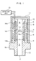
- Fig. 1 shows a pressure sensor of the present invention.
- the pressure sensor comprises a cylindrical main body 1 made of titanium and having an outer diameter (D) of 10 mm (at a recess 14) and an entire length of 70 mm, a film 7 of an amorphous magnetic alloy mounted around the outer periphery of the body 1, a cylindrical bobbin 10 of a phenolic resin disposed radially outwardly of the film 7 and mounted around the outer periphery of the body 1, a pressure detector coil 8 wound on the outer periphery of the bobbin 10, a dummy coil 9 wound on the outer periphery of the bobbin 10, a yoke 11 of 45%Ni-Fe alloy disposed radially outwardly of the coils 8 and 9, and a detector unit 13 electrically connected to the two coils 8 and 9.
- the body 1 has two central holes separated from each other by a partition wall 1a, the two central holes defining a pressure chamber 3 and an dummy (or reference) chamber 6, respectively.
- the body 1 also has a pressure introducing opening 2 defined by an open end of the pressure chamber 3, a greater-diameter flange 1b formed on the outer periphery of the body 1 and disposed adjacent to the end of the body 1 having the pressure introducing opening 2, the above mentioned recess (smallest-diameter portion) 14 formed in the outer periphery of the body 1 and extending throughout the entire length of the smaller-diameter portion of the body 1 between the end portion of the body 1 remote from the pressure introducing opening 2 and the greater-diameter flange 1b, and a fixing screw thread 12 formed on the outer periphery of the end portion of the body 1 close the pressure introducing opening 2.
- a wall part which defines part of the pressure chamber 3 and exists between the pressure chamber 3 and the recess 14 is a deforming part 4 which is deformed in response to a change in the pressure within the pressure chamber 3.
- Another wall part, being integrated with the above-mentioned wall, which defines part of the dummy chamber 6 and exists between the dummy chamber 6 and the recess 14 is a non-deforming part 5 which is not influenced by the pressure within the pressure chamber 3.
- the depth of the recess 14, that is, the height of steps 14a arid 14b, is 0.2 mm in this embodiment.
- the film 7 is received in the recess 14 and is wound around the outer periphery of the body 1.
- the film 7 is a rectangular thin sheet of an amorphous magnetic alloy having a thickness of 0.03 mm.
- This amorphous magnetic alloy is of the Fe-Si-B-Cr type.
- the amorphous magnetic alloy film 7 is fixedly bonded to the body 1 by an imide-system adhesive as a bonding material.
- a pressure of 10 atm. is applied to the film 7 at 250°C for one hour.
- the bonding of the film 7 by application of pressure is carried out by fitting a tube of a heat-shrinkable resin on the film 7 and then by heating this tube to shrink.
- the tube is removed.
- the steps 14a and 14b serve as positioning means which prevents the film 7 from being displaced along the axis of the body 1 during bonding of the film 7 by the adhesive.
- the circumferential length of the film 7 may be sufficiently long to surround the outer periphery of the body 1, either with the opposite side edge portions of the film 7 overlapping each other, or with the opposite side edges of the film 7 butted together (see Example 5). Alternatively, the circumferential length of the film 7 may be shorter not to completely surround the outer periphery of the body 1, with the opposite side edges of the film 7 spaced apart from each other.
- the bobbin 10 having two peripheral grooves is fitted on the body 1 to cover the recess 14.
- the pressure detector coil 8 (whose number of turns is 100) is received in one of the two peripheral grooves close to the flange 1b, and the dummy coil 9 (whose number of turns is 100) is received in the other peripheral groove.
- the both coils 8 and 9 are used as permeability detector elements, and cooperate with the amorphous magnetic alloy film 7 to form a magnetic circuit.
- the detector unit 13 comprises resistors which constitute, together with the coils 8 and 9, a bridge, and a differential amplifier.
- the yoke 11 is a magnetic shield member of a cylindrical cup-shape, and is fixedly secured by an adhesive to the bobbin 10 and/or the flange 1b to cover the bobbin 10.
- the operation of the pressure sensor of this example will now be described.
- the pressure of a fluid to be measured is transmitted to the pressure chamber 3 via the pressure introducing opening 2, and applies a force in a direction to expand the deforming part 4 defining the pressure chamber 3.
- the part 4 is deformed, so that the amorphous magnetic alloy film 7 adhesively bonded to the outer surface of the part 4 is deformed.
- This deformation changes the permeability of the amorphous magnetic alloy film 7 due to the magnetostriction effect.
- This permeability change is detected by the pressure detector coil 8 as a change in inductance, and the pressure change is obtained by detecting a differential output between the coil 8 and the dummy coil 9 through the detector unit 13.
- the yield rate of the pressure sensor of the example, in manufacturing of the sensor is about 70%, and is about two times higher than that of the conventional pressure sensor. The reason for this is that at the time of coating the adhesive, the excess of the adhesive tending to cause irregularities in the adhesive layer escapes to a space 14C defined by the greater steps 14a and 14b, so that the bonding conditions on the both parts 4 and 5 become closer to a uniform condition.
- the pressure sensor having a higher yield rate than those of conventional sensors was obtained.
- FIG. 2 A second example of the present invention will now be described with reference to Figs. 2 and 3a - 3c.
- Those portions of this example identical respectively to those of the first example of Fig. 1 and the prior art of Fig. 7 and 8a - 8c are designated by identical reference numerals, respectively, and explanation thereof will be omitted, and only those portions constituting features of this example will be described.
- an imide-system adhesive which is used to bond an amorphous magnetic alloy film 7 to a body 1 is also coated, as a buffer material (easily-deformable pressure-applying medium), onto an outer surface of the amorphous magnetic alloy film 7 (see Fig. 2).
- the use of the buffer-material 15 eliminates the effects of the non-uniformity of a heat-shrinkable tube 21. This condition is shown in Figs. 3a to 3c which are enlarged views of that portion of Fig. 1 indicated by a dotted line. It will be appreciated that no matter how the heat-shrinkable tube 21 is shrunk, the adhesive layer 22 inside the amorphous magnetic alloy film 7 is made unifrom in thickness, so that the uniform bonding can be achieved.
- the pressure sensor of this example achieved a yield rate of 100% in manufacturing of the sensor and higher corrosion resistance than those of conventional sensors.
- the pressure sensor of this example was dipped in hot water of 80°C for about one week, but no corrosion was found on the surface of the film 7.
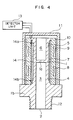
- FIG. 4 A third example of the invention will now be described with reference to Fig. 4.
- the present example is basically similar in structure to the first example of Fig. 1, and therefore detailed description of the present example will be omitted, and only those portions constituting features of this example will be described.
- each of steps 14a and 14b has the shape of a two-step stair (see Fig. 4).
- the height of the inner step portion is 0.1 mm, and the height of the outer step portion is 0.2 mm.
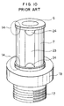
- An amorphous magnetic alloy film 7 was adhesively bonded to a body 1 having the steps 14a and 14b of such a shape, and a heat cycle test (cycle of -40°C and 150°C) was conducted 800 times. As a result, no exfoliation part as shown in Fig. 10 was recognized.
- the number of the step portions of the stair-like steps 14a and 14b is two, it may be more than two in which case the adhesive can be dispersed more effectively, so that the stress concentration is further restrained, thereby improving the durability.
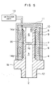
- FIG. 5 A fourth example of the invention will now be described with reference to Fig. 5.
- the present example is basically similar in structure to the first example of Fig. 1, and therefore detailed description of this example will be omitted, and only those portions constituting features of this example will be described.
- each of steps 14a and 14b is tapered or inclined (see Fig. 5).
- the width (w) of the tapered portion is 1 mm.
- An amorphous magnetic alloy film 7 was adhesively bonded to a body 1 having the steps 14a and 14b of such a tapered shape, and a heat cycle test (cycle of -40°C and 150°C) was conducted 800 times. As a result, as in the third example, no exfoliation part as shown in Fig. 10 was recognized.
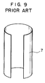
- the circumferential length of an amorphous magnetic alloy film 7 is equal to the circumferential length of a cylindrical body 1 (Fig. 1), so that the film 7 has such a shape as shown in Fig. 6. Therefore, when the film 7 is adhesively bonded on the surface of the body 1 including a deforming part 4 and a non-deforming part 5, a gap as designated at 23 in Fig. 10 will not be formed, and the cylindrical body 1 is completely surrounded by the film 7 over the entire circumference of the body 1.
- the pressure sensor of this example was subjected to a heat cycle test (cycle of -40°C and 150°C) 500 times. As a result, as in the third example, no exfoliation part as designated at 24 in Fig. 10 was recognized.
Landscapes
- Physics & Mathematics (AREA)
- General Physics & Mathematics (AREA)
- Measuring Fluid Pressure (AREA)
Claims (12)
- Druckfühler mit einem Druckeinleitungsbereich (2), einem zylindrischen verformbaren Teil (4), das eine Druckkammer (3) begrenzt, welche von einem ihr über den Druckeinleitungsbereich (2) zugeführten Druck verformbar ist, einem zylindrischen nichtverformbaren Teil (5), einer an dem verformbaren Teil (4) und dem nichtverformbaren Teil (5) festgelegten dünnen Schicht aus einer amorphen Magnetlegierung (7) mit magnetostriktiver Wirkung, und einem Paar von zur Erfassung der Permeabilität der amorphen dünnen Magnetlegierungsschicht (7) an dem verformbaren Teil (4) bzw. dem nichtverformbaren Teil (5) festgelegten Permeabilitätsdetektorelementen (8, 9), die mit der amorphen dünnen Magnetlegierungsschicht (7) zur Bildung eines Magnetkreises zusammenwirken, wobei der Druck durch die zwischen den von dem Paar von Permeabilitätsdetektorelementen (8, 9) jeweils erfaßten Permeabilitäten bestehende Differenz bestimmt wird, welche bei der Einleitung von Druck in die Druckkammer (3) auftritt, eine Ausnehmung in den Außenseiten des verformbaren Teils und des nichtverformbaren Teils derart ausgebildet ist, daß ein Paar von Stufen (14a, 14b) jeweils an entgegengesetzten Enden der Ausnehmung gebildet ist, die Tiefe der Ausnehmung (14) größer ist als die Gesamtdicke der amorphen dünnen Magnetlegierungsschicht (7) und einer Haftschicht (22), und die amorphe dünne Magnetlegierungsschicht (7) in der Ausnehmung aufgenommen und in bezug auf diese festgelegt ist und sich zwischen dem Paar von Stufen (14a, 14b) erstreckt.
- Druckfühler nach Anspruch 1, bei dem die dünne Schicht (7) innerhalb der Ausnehmung (14) um die äußere Umfangsfläche des Körpers herumgewunden und darauf mit einem Bindewerkstoff festgeklebt ist.
- Druckfühler nach Anspruch 2, bei dem der Bindewerkstoff ein Imidsystemkleber ist.
- Druckfühler nach Anspruch 1, bei dem ein Pufferwerkstoff auf eine äußere Oberfläche der amorphen dünnen Magnetlegierungsschicht (7) aufgebracht ist.
- Druckfühler nach Anspruch 1, bei dem jede der Stufen (14a, 14b) die Form von mindestens zwei Stufen aufweist.
- Druckfühler nach Anspruch 1, bei dem jede der Stufen (14a, 14b) eine konisch verjüngte Form aufweist.
- Druckfühler nach einem der Ansprüche 2 bis 6, bei dem die amorphe dünne Magnetlegierungsschicht (7) umfänglich die gesamte zylindrische Außenoberfläche des den verformbaren Teil (4) und den nichtverformbaren Teil (5) aufweisenden, mit der Ausnehmung (14) versehenen Bereichs bedeckt.
- Druckfühler nach Anspruch 4, bei dem der Pufferwerkstoff ein Bindewerkstoff ist.
- Druckfühler mit einem Druckeinleitungsbereich (2), einem zylindrischen verformbaren Teil (4), das eine Druckkammer (3) begrenzt, welche von einem ihr über den Druckeinleitungsbereich (2) zugeführten Druck verformbar ist, einem zylindrischen nichtverformbaren Teil (5), einer an dem verformbaren Teil (4) und dem nichtverformbaren Teil (5) festgelegten dünnen Schicht aus einer amorphen Magnetlegierung (7) mit magnetostriktiver Wirkung, und einem Paar von zur Erfassung der Permeabilität der amorphen dünnen Magnetlegierungsschicht (7) an dem verformbaren Teil (4) bzw. dem nichtverformbaren Teil (5) festgelegten Permeabilitätsdetektorelementen (8, 9), die mit der amorphen dünnen Magnetlegierungsschicht (7) zur Bildung eines Magnetkreises zusammenwirken, wobei der Druck durch die zwischen den von dem Paar von Permeabilitätsdetektorelementen (8, 9) jeweils erfaßten Permeabilitäten bestehende Differenz bestimmt wird, welche bei der Einleitung von Druck in die Druckkammer (3) auftritt, eine Ausnehmung in den Außenseiten des verformbaren Teils und des nichtverformbaren Teils derart ausgebildet ist, daß ein Paar von Stufen (14a, 14b) jeweils an entgegengesetzten Enden der Ausnehmung gebildet ist, ein Pufferwerkstoff (15) auf eine äußere Oberfläche der amorphen dünnen Magnetlegierungsschicht (7) aufgebracht ist, und die amorphe dünne Magnetlegierungsschicht (7) in der Ausnehmung (14) aufgenommen ist und sich zwischen dem Paar von Stufen (14a, 14b) derart erstreckt, daß sie umfänglich die gesamte zylindrische Außenoberfläche eines den verformbaren Teil (4) und den nichtverformbaren Teil (5) aufweisenden Abschnittes bedeckt.
- Druckfühler nach Anspruch 9, bei dem jede Stufe (14a, 14b) die Form von mindestens zwei Stufen aufweist.
- Druckfühler nach Anspruch 9, bei dem jede Stufe (14a, 14b) eine sich konisch verjüngende Form aufweist.
- Druckfühler nach Anspruch 9, bei dem der Pufferwerkstoff (15) ein Bindewerkstoff ist.
Applications Claiming Priority (6)
| Application Number | Priority Date | Filing Date | Title |
|---|---|---|---|
| JP90804/90 | 1990-04-05 | ||
| JP9080490A JPH0797059B2 (ja) | 1990-04-05 | 1990-04-05 | 圧力センサ |
| JP227054/90 | 1990-08-28 | ||
| JP2227054A JPH04106444A (ja) | 1990-08-28 | 1990-08-28 | 圧力センサ |
| JP3001726A JPH04235324A (ja) | 1991-01-10 | 1991-01-10 | 圧力センサ |
| JP1726/91 | 1991-01-10 |
Publications (2)
| Publication Number | Publication Date |
|---|---|
| EP0450933A1 EP0450933A1 (de) | 1991-10-09 |
| EP0450933B1 true EP0450933B1 (de) | 1994-09-28 |
Family
ID=27275040
Family Applications (1)
| Application Number | Title | Priority Date | Filing Date |
|---|---|---|---|
| EP91302919A Expired - Lifetime EP0450933B1 (de) | 1990-04-05 | 1991-04-03 | Magnetoresistiver Druckaufnehmer |
Country Status (4)
| Country | Link |
|---|---|
| US (1) | US5165284A (de) |
| EP (1) | EP0450933B1 (de) |
| KR (1) | KR930005167B1 (de) |
| DE (1) | DE69104255T2 (de) |
Families Citing this family (23)
| Publication number | Priority date | Publication date | Assignee | Title |
|---|---|---|---|---|
| US4938069A (en) * | 1988-10-26 | 1990-07-03 | Matsushita Electric Industrial Co., Ltd. | Pressure sensor |
| JPH04184233A (ja) * | 1990-11-19 | 1992-07-01 | Matsushita Electric Ind Co Ltd | 圧力センサ |
| JPH05296866A (ja) * | 1992-04-23 | 1993-11-12 | Matsushita Electric Ind Co Ltd | 圧力センサ |
| JPH06216426A (ja) * | 1992-06-09 | 1994-08-05 | Nippondenso Co Ltd | 磁歪層形成方法およびそれを用いた歪センサ |
| US5672812A (en) * | 1995-10-10 | 1997-09-30 | Southwest Research Institute | Sparkplug/pressure sensor device |
| DE19611189C2 (de) * | 1996-03-21 | 2000-11-23 | Daimler Chrysler Ag | Magnetoelastischer Druckaufnehmer |
| JP2001116551A (ja) | 1999-10-18 | 2001-04-27 | Matsushita Electric Ind Co Ltd | 角速度センサ |
| US6523614B2 (en) * | 2001-04-19 | 2003-02-25 | Halliburton Energy Services, Inc. | Subsurface safety valve lock out and communication tool and method for use of the same |
| CA2636887C (en) * | 2003-10-27 | 2012-03-13 | Baker Hughes Incorporated | Tubing retrievable safety valve and method |
| US7104137B2 (en) * | 2004-04-20 | 2006-09-12 | Delphi Technologies, Inc. | Magnetostrictive fluid-pressure sensor |
| DE102005018938A1 (de) * | 2005-04-22 | 2006-11-02 | Siemens Ag | Drucksensor |
| DE102006018480A1 (de) * | 2005-04-27 | 2006-11-02 | Continental Teves Ag & Co. Ohg | Magnetomechanischer Drucksensor |
| WO2006117293A1 (de) * | 2005-05-03 | 2006-11-09 | Continental Teves Ag & Co.Ohg | Magnetoelastischer drucksensor |
| TWI310689B (en) * | 2006-02-09 | 2009-06-11 | Ind Tech Res Inst | Flexible antenna device for energy transmission,method for control the same and method for energy transmission of the same,flexible antenna module for wireless energy transmission and an energy transmission apparatus containing the same and method for en |
| CN101020095B (zh) * | 2006-02-16 | 2011-06-15 | 财团法人工业技术研究院 | 可挠式无线传能天线模块 |
| CN101405587B (zh) * | 2006-03-29 | 2010-11-17 | 株式会社Jms | 压力检测装置 |
| KR101012767B1 (ko) * | 2008-05-06 | 2011-02-08 | 한국표준과학연구원 | 자기변형 진동자를 이용한 용기부 내의 압력측정장치 |
| DE102008044125A1 (de) * | 2008-11-27 | 2010-06-02 | Robert Bosch Gmbh | Sensoranordnung mit einem magnetoelastischen Verformungselement |
| US8327713B2 (en) * | 2008-12-03 | 2012-12-11 | Rosemount Inc. | Method and apparatus for pressure measurement using magnetic property |
| DE102011082487A1 (de) * | 2011-09-12 | 2013-03-14 | Siemens Aktiengesellschaft | Verfahren und Sensoranordnung zum Messen des Drucks in einem Druckgefäß |
| EP3276323B1 (de) * | 2015-03-23 | 2020-04-29 | Nabtesco Corporation | Drucksensor |
| US10082431B2 (en) | 2015-07-17 | 2018-09-25 | Honeywell International Inc. | System and methods for magnetic tunnel junction pressure sensors |
| CN114216537B (zh) * | 2021-12-14 | 2024-11-05 | 常州研拓智能科技有限公司 | 一种具有防腐蚀功能的磁致伸缩传感器 |
Family Cites Families (4)
| Publication number | Priority date | Publication date | Assignee | Title |
|---|---|---|---|---|
| US3197722A (en) * | 1961-06-07 | 1965-07-27 | Int Resistance Co | Pressure transducer |
| US4625562A (en) * | 1984-06-08 | 1986-12-02 | Matsushita Electric Industrial Co., Ltd. | Amorphous magnetic alloy sensor |
| DE3604088A1 (de) * | 1986-02-08 | 1987-08-13 | Daimler Benz Ag | Drucksensor |
| US4938069A (en) * | 1988-10-26 | 1990-07-03 | Matsushita Electric Industrial Co., Ltd. | Pressure sensor |
-
1991
- 1991-04-01 US US07/678,160 patent/US5165284A/en not_active Expired - Lifetime
- 1991-04-03 DE DE69104255T patent/DE69104255T2/de not_active Expired - Fee Related
- 1991-04-03 EP EP91302919A patent/EP0450933B1/de not_active Expired - Lifetime
- 1991-04-04 KR KR1019910005450A patent/KR930005167B1/ko not_active Expired - Fee Related
Also Published As
| Publication number | Publication date |
|---|---|
| DE69104255D1 (de) | 1994-11-03 |
| KR910018790A (ko) | 1991-11-30 |
| DE69104255T2 (de) | 1995-05-11 |
| US5165284A (en) | 1992-11-24 |
| EP0450933A1 (de) | 1991-10-09 |
| KR930005167B1 (ko) | 1993-06-16 |
Similar Documents
| Publication | Publication Date | Title |
|---|---|---|
| US5165284A (en) | Pressure sensor utilizing a magnetostriction effect | |
| EP0471073A1 (de) | Zylinderkonstruktion zur verwendung bei positionsmessungen | |
| US4986137A (en) | Strain detector with magnetostrictive elements | |
| JPH0326339B2 (de) | ||
| JPS6373800A (ja) | 高感度圧電水中聴音器 | |
| US5353649A (en) | Non-contact detecting type torque sensor | |
| GB2169400A (en) | Fibre optic magnetic sensor | |
| US5303595A (en) | Pressure sensor utilizing magnetostriction effect | |
| EP0146382B1 (de) | Berührungsfreie Drehmomentfühler | |
| JPH07101747B2 (ja) | 半導体圧力センサ | |
| EP0567056A1 (de) | Drucksensor | |
| EP0371244A2 (de) | Magnetostriktiver Druckwandler | |
| JPS62228927A (ja) | 圧力センサ | |
| JP2000292294A (ja) | 密閉容器の内部圧力検出用センサ | |
| JP2641741B2 (ja) | 力学量センサ | |
| JPH04106444A (ja) | 圧力センサ | |
| JPH05118932A (ja) | 荷重センサ | |
| JPH034846B2 (de) | ||
| JP3416856B2 (ja) | トルクセンサ | |
| JPH0310138A (ja) | 圧力センサ | |
| CA1222396A (en) | Torque sensor of noncontact type | |
| JP2894011B2 (ja) | 電磁流量計検出器 | |
| JPH03131733A (ja) | 圧力センサ | |
| JPH0355875Y2 (de) | ||
| SU1723472A1 (ru) | Датчик разности давлений |
Legal Events
| Date | Code | Title | Description |
|---|---|---|---|
| PUAI | Public reference made under article 153(3) epc to a published international application that has entered the european phase |
Free format text: ORIGINAL CODE: 0009012 |
|
| AK | Designated contracting states |
Kind code of ref document: A1 Designated state(s): DE FR GB |
|
| 17P | Request for examination filed |
Effective date: 19911204 |
|
| 17Q | First examination report despatched |
Effective date: 19930430 |
|
| GRAA | (expected) grant |
Free format text: ORIGINAL CODE: 0009210 |
|
| AK | Designated contracting states |
Kind code of ref document: B1 Designated state(s): DE FR GB |
|
| REF | Corresponds to: |
Ref document number: 69104255 Country of ref document: DE Date of ref document: 19941103 |
|
| ET | Fr: translation filed | ||
| PLBE | No opposition filed within time limit |
Free format text: ORIGINAL CODE: 0009261 |
|
| STAA | Information on the status of an ep patent application or granted ep patent |
Free format text: STATUS: NO OPPOSITION FILED WITHIN TIME LIMIT |
|
| 26N | No opposition filed | ||
| REG | Reference to a national code |
Ref country code: GB Ref legal event code: IF02 |
|
| PGFP | Annual fee paid to national office [announced via postgrant information from national office to epo] |
Ref country code: FR Payment date: 20030408 Year of fee payment: 13 |
|
| PGFP | Annual fee paid to national office [announced via postgrant information from national office to epo] |
Ref country code: DE Payment date: 20030409 Year of fee payment: 13 |
|
| PGFP | Annual fee paid to national office [announced via postgrant information from national office to epo] |
Ref country code: GB Payment date: 20040331 Year of fee payment: 14 |
|
| PG25 | Lapsed in a contracting state [announced via postgrant information from national office to epo] |
Ref country code: DE Free format text: LAPSE BECAUSE OF NON-PAYMENT OF DUE FEES Effective date: 20041103 |
|
| PG25 | Lapsed in a contracting state [announced via postgrant information from national office to epo] |
Ref country code: FR Free format text: LAPSE BECAUSE OF NON-PAYMENT OF DUE FEES Effective date: 20041231 |
|
| REG | Reference to a national code |
Ref country code: FR Ref legal event code: ST |
|
| PG25 | Lapsed in a contracting state [announced via postgrant information from national office to epo] |
Ref country code: GB Free format text: LAPSE BECAUSE OF NON-PAYMENT OF DUE FEES Effective date: 20050403 |
|
| GBPC | Gb: european patent ceased through non-payment of renewal fee |
Effective date: 20050403 |