EP0451011B1 - Kolben für Brennkraftmaschinen - Google Patents
Kolben für Brennkraftmaschinen Download PDFInfo
- Publication number
- EP0451011B1 EP0451011B1 EP91400791A EP91400791A EP0451011B1 EP 0451011 B1 EP0451011 B1 EP 0451011B1 EP 91400791 A EP91400791 A EP 91400791A EP 91400791 A EP91400791 A EP 91400791A EP 0451011 B1 EP0451011 B1 EP 0451011B1
- Authority
- EP
- European Patent Office
- Prior art keywords
- shell
- piston
- connecting rod
- pressure
- little
- Prior art date
- Legal status (The legal status is an assumption and is not a legal conclusion. Google has not performed a legal analysis and makes no representation as to the accuracy of the status listed.)
- Expired - Lifetime
Links
- 238000002485 combustion reaction Methods 0.000 title claims description 8
- 239000003921 oil Substances 0.000 claims description 22
- 239000010687 lubricating oil Substances 0.000 claims description 8
- 239000002184 metal Substances 0.000 claims description 8
- 239000000463 material Substances 0.000 claims description 7
- 238000011144 upstream manufacturing Methods 0.000 claims description 7
- 230000002706 hydrostatic effect Effects 0.000 claims description 5
- 230000000694 effects Effects 0.000 claims description 3
- 238000003466 welding Methods 0.000 claims description 2
- 239000012858 resilient material Substances 0.000 claims 1
- 230000005499 meniscus Effects 0.000 description 9
- 239000012530 fluid Substances 0.000 description 6
- 229910000831 Steel Inorganic materials 0.000 description 5
- 239000010959 steel Substances 0.000 description 5
- 125000006850 spacer group Chemical group 0.000 description 4
- 230000005540 biological transmission Effects 0.000 description 3
- 239000013013 elastic material Substances 0.000 description 3
- 229910000906 Bronze Inorganic materials 0.000 description 2
- 230000003416 augmentation Effects 0.000 description 2
- 239000010974 bronze Substances 0.000 description 2
- 230000006835 compression Effects 0.000 description 2
- 238000007906 compression Methods 0.000 description 2
- 238000001816 cooling Methods 0.000 description 2
- KUNSUQLRTQLHQQ-UHFFFAOYSA-N copper tin Chemical compound [Cu].[Sn] KUNSUQLRTQLHQQ-UHFFFAOYSA-N 0.000 description 2
- 238000005461 lubrication Methods 0.000 description 2
- 238000007789 sealing Methods 0.000 description 2
- 208000031968 Cadaver Diseases 0.000 description 1
- 241001080024 Telles Species 0.000 description 1
- 230000001133 acceleration Effects 0.000 description 1
- 230000004888 barrier function Effects 0.000 description 1
- 230000000903 blocking effect Effects 0.000 description 1
- 239000000470 constituent Substances 0.000 description 1
- 238000010276 construction Methods 0.000 description 1
- 230000007547 defect Effects 0.000 description 1
- 230000008030 elimination Effects 0.000 description 1
- 238000003379 elimination reaction Methods 0.000 description 1
- 239000000835 fiber Substances 0.000 description 1
- 230000014509 gene expression Effects 0.000 description 1
- 238000005192 partition Methods 0.000 description 1
- 235000011837 pasties Nutrition 0.000 description 1
- 230000000284 resting effect Effects 0.000 description 1
- 238000000926 separation method Methods 0.000 description 1
- 230000001052 transient effect Effects 0.000 description 1
- 238000005303 weighing Methods 0.000 description 1
Images


Classifications
-
- F—MECHANICAL ENGINEERING; LIGHTING; HEATING; WEAPONS; BLASTING
- F02—COMBUSTION ENGINES; HOT-GAS OR COMBUSTION-PRODUCT ENGINE PLANTS
- F02F—CYLINDERS, PISTONS OR CASINGS, FOR COMBUSTION ENGINES; ARRANGEMENTS OF SEALINGS IN COMBUSTION ENGINES
- F02F3/00—Pistons
- F02F3/0015—Multi-part pistons
- F02F3/0023—Multi-part pistons the parts being bolted or screwed together
-
- F—MECHANICAL ENGINEERING; LIGHTING; HEATING; WEAPONS; BLASTING
- F16—ENGINEERING ELEMENTS AND UNITS; GENERAL MEASURES FOR PRODUCING AND MAINTAINING EFFECTIVE FUNCTIONING OF MACHINES OR INSTALLATIONS; THERMAL INSULATION IN GENERAL
- F16J—PISTONS; CYLINDERS; SEALINGS
- F16J1/00—Pistons; Trunk pistons; Plungers
- F16J1/10—Connection to driving members
- F16J1/14—Connection to driving members with connecting-rods, i.e. pivotal connections
- F16J1/22—Connection to driving members with connecting-rods, i.e. pivotal connections with universal joint, e.g. ball-joint
-
- F—MECHANICAL ENGINEERING; LIGHTING; HEATING; WEAPONS; BLASTING
- F02—COMBUSTION ENGINES; HOT-GAS OR COMBUSTION-PRODUCT ENGINE PLANTS
- F02B—INTERNAL-COMBUSTION PISTON ENGINES; COMBUSTION ENGINES IN GENERAL
- F02B75/00—Other engines
- F02B75/02—Engines characterised by their cycles, e.g. six-stroke
- F02B2075/022—Engines characterised by their cycles, e.g. six-stroke having less than six strokes per cycle
- F02B2075/025—Engines characterised by their cycles, e.g. six-stroke having less than six strokes per cycle two
-
- F—MECHANICAL ENGINEERING; LIGHTING; HEATING; WEAPONS; BLASTING
- F02—COMBUSTION ENGINES; HOT-GAS OR COMBUSTION-PRODUCT ENGINE PLANTS
- F02B—INTERNAL-COMBUSTION PISTON ENGINES; COMBUSTION ENGINES IN GENERAL
- F02B75/00—Other engines
- F02B75/02—Engines characterised by their cycles, e.g. six-stroke
- F02B2075/022—Engines characterised by their cycles, e.g. six-stroke having less than six strokes per cycle
- F02B2075/027—Engines characterised by their cycles, e.g. six-stroke having less than six strokes per cycle four
-
- F—MECHANICAL ENGINEERING; LIGHTING; HEATING; WEAPONS; BLASTING
- F05—INDEXING SCHEMES RELATING TO ENGINES OR PUMPS IN VARIOUS SUBCLASSES OF CLASSES F01-F04
- F05C—INDEXING SCHEME RELATING TO MATERIALS, MATERIAL PROPERTIES OR MATERIAL CHARACTERISTICS FOR MACHINES, ENGINES OR PUMPS OTHER THAN NON-POSITIVE-DISPLACEMENT MACHINES OR ENGINES
- F05C2201/00—Metals
- F05C2201/04—Heavy metals
- F05C2201/0433—Iron group; Ferrous alloys, e.g. steel
- F05C2201/0448—Steel
-
- F—MECHANICAL ENGINEERING; LIGHTING; HEATING; WEAPONS; BLASTING
- F05—INDEXING SCHEMES RELATING TO ENGINES OR PUMPS IN VARIOUS SUBCLASSES OF CLASSES F01-F04
- F05C—INDEXING SCHEME RELATING TO MATERIALS, MATERIAL PROPERTIES OR MATERIAL CHARACTERISTICS FOR MACHINES, ENGINES OR PUMPS OTHER THAN NON-POSITIVE-DISPLACEMENT MACHINES OR ENGINES
- F05C2251/00—Material properties
- F05C2251/04—Thermal properties
- F05C2251/042—Expansivity
Definitions
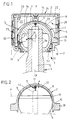
- the piston 1 comprises unidirectional means for supplying lubrication oil under pressure which communicate upstream, by means of a non-return valve 11, with an oil passage 12 arranged in the connecting rod 3 and passing through its foot 6 and which open, preferably in the axis of the connecting rod 3, in a gap or meniscus 13 delimited by the parts of the foot 6 and of the shell 7 located above the line 9 or strip 10 of contact.
- a non-return valve 11 At least during part of the compression-expansion cycle of the working gas which acts inside the cylinder 2 on the transverse surface 14 of the piston 1 remote from the connecting rod 3, the pressure of the lubricating oil, upstream of the non-return valve 11, is greater than the pressure prevailing in the gap 13.
- the space 15 located between the connecting rod end 6 and the shell 7, below the line 9 or strip 10 of contact communicates with a discharge area at relatively low pressure, lower than the pressure prevailing in the gap 13.
Landscapes
- Engineering & Computer Science (AREA)
- General Engineering & Computer Science (AREA)
- Chemical & Material Sciences (AREA)
- Combustion & Propulsion (AREA)
- Mechanical Engineering (AREA)
- Pistons, Piston Rings, And Cylinders (AREA)
- Compressor (AREA)
- Lubrication Of Internal Combustion Engines (AREA)
- Shafts, Cranks, Connecting Bars, And Related Bearings (AREA)
Claims (10)
- Kolben bestimmt zum Hin- und Hergleiten in Zylindern von Kolbenkraftmschinen mit innerer oder äußerer Verbrennung und von Kompressoren, das heißt von Maschinen, in denen ein Arbeitsgas, das in dem oder in jedem Zylinder (2) durch eine Querfläche (14) des Kolbens (1) gehalten, sich gleichzeitig unter hohem Druck und hoher Temperatur befindet, vorzugsweise Kolben für Kolbenkraftmaschinen mit innerer Verbrennung im Zweitakt- oder Viertaktverfahren, welche im Innern eines außen zylindrischen Körpers (4) einen Innenhohlraum (5) aufweisen, in dem der teilweise sphärische Fuß (6) einer Kolbenstange (3) und eine dichte Kokille (7) gelagert sind, welche eine nahezu halbkugelförmige Kappe (8) hat, deren Rand ringförmig mit dem Innenteil des Körpers (4) des Kolbens (1) verbunden ist, wobei diese Kokille (7) so gestaltet ist, daß ihre nahezu halbkugelförmige Kappe (8), wenn der Kolben (1) sich in Ruhestellung befindet oder wenn der Druck im Laufe eines Verdichtung-Expansion-Zyklus auf dem teilweise sphärischen Fuß (6) der Kolbenstange (3) nur entlang einer geschlossenen kreisförmigen Kontakt-Linie (9) ruht oder eines solchen Kontakt-Streifens (10), der gelegen ist in, oder an seinem oberen Teil begrenzt ist von, einer Fläche (P), die über dem Mittelpunkt (C) des Kolbenstangenfußes (8) und vorzugsweise senkrecht zur Achse (X-X) des Kolbens (1) verläuft, wobei dieser Kolben (1) Einwegvorrichtungen enthält für die Zuleitung des Schmieröls unter Druck, welche oberstromig mittels eines Rückschlagventils (11) mit einer in der Kolbenstange (3) angelegten Ölleitung (12) kommunizieren und welche vorzugsweise in der Achse der Kolbenstange in einen Zwischenraum (13) münden, der begrenzt wird von den Teilen der Oberfläche des Kolbenstangenfußes (6) und der Kokille (7), die oberhalb besagter Kontakt-Linie (9) oder besagten Kontakt-Streifens (10) liegen, wobei der Druck des Schmieröls oberstromig von besagtem Rückschlagventil (11) zumindest während eines Teils des Verdichtung-Expansion-Zyklus des Arbeitsgases höher ist als der in besagtem Zwischenraum (13) herrschende Druck, da der zwischen dem Kolbenstangenfuß (6) und der Kokille (7) unter der besagten Kontakt-Linie oder dem besagten Kontakt-Streifen liegende Raum kommuniziert mit einer Auspuffzone relativ niederen Druckes, der niedriger ist als der Höchstdruck, der in besagtem Zwischenraum (13) herrscht,
gekennzeichnet durch folgende Merkmale:- der Raum (16), der im Inneren des besagten Hohlraums (5) begrenzt ist durch die Oberflächen (17) der Kokille (7), die vom Kolbenstangentuß (6) entfernt ist, ist so angelegt, daß sich darin im Betrieb aufgrund der Verformung der Kokille (7) kein nennenswerter hydrostatischer Druck entwickeln kann;- die Kokille (7) wird im Betrieb gespannt gehalten zwischen dem teilweise sphärischen Fuß (6) der Kolbenstange (3) und dem ringförmigen Bereich, durch den ihr Rand mit dem Unterteil des Körpers (4) des Kolbens (1) verbunden ist;- die Kokille (7) ist gefertigt aus einem Metall oder einem anderen, gleichwertigen elastischen Material und hat eine ausreichend große Dicke, damit diese Kokille (7) in der Lage ist, die im Betrieb von dem Arbeitsgas auf besagte Querfläche (14) des Kolbens (1) ausgeübten und von der Kokille (7) mittels ihres ringförmigen Verbundbereichs empfangenen Kräfte auf den teilweise sphärischen Fuß (6) des Kolbens (3) zu übermitteln, wobei die Dicke dieser Kokille (7) jedoch hinreichend gering ist, damit sie sich unter der Wirkung der Spannung vorformen kann, welche aus den vom Druck des Arbeitsgases zyklisch auf die Querfläche (14) des Kolbens (1) ausgeübten und mittels der Kokille (7) auf die Kolbenstange übertragenen Kräften resultiert, und zwar so, daß sie das Volumen des Zwischenraums (13) zyklisch verkleinert und vorzugsweise die Fläche des Kontaktstreifens (10) zyklisch vergrößert, wobei die Minimal- und Maximal-Grenzwerte, welche die Dicke der Kokille (7) aufweisen muß, so sind, daß das Material, aus dem sie hergestellt ist, auf keinen Fall seine Beanspruchungsgrenzen überschreitet. - Kolben nach Anspruch 1, dadurch gekennzeichnet, daß der im Innern des besagten Hohlraums (5) begrenzte Raum (16) abgeschlossen und mit einem Gas gefüllt ist.
- Kolben nach Anspruch 1, dadurch gekennzeichnet, daß der im Innern des besagten Hohlraums (5) begrenzte Raum (16) zumindest teilweise mit einem Schmieröl gefüllt und mit einer Auspuffzone relativ geringen Drucks verbunden ist.
- Kolben nach Anspruch 3, dadurch gekennzeichnet, daß der Raum (16) mit einem Öl gespeist wird, das den Einwegvorrichtungen für die Zuleitung des Schmieröls (11, 12) oberstromig von ihrem Rückschlagventil (11) entnommen wird.
- Kolben nach einem der Ansprüche 1 - 4, dadurch gekennzeichnet, daß der Rand der Kokille (7) mit dem Unterteil des Kolbenkörpers (4) durch Verschweißen (37) verbunden ist.
- Kolben nach einem der Ansprüche 1-4, dadurch gekennzeichnet, daß der Rand der Kokille (7) mit dem Unterteil des Kolbenkörpers (4) verbunden ist durch Gestaltung der Kokille (7) und des Kolbenkörpers (4) in einem einzigen Stück.
- Kolben nach einem der Ansprüche 1 - 4, dadurch gekennzeichnet, daß der Rand der Kokille (7) mit dem Unterteil des Kolbenkörpers (4) verbunden ist durch Quetschung eines Ringes (18), der den Rand der Kokille (7) bildet, zwischen dem Kolbenkörper (4) und einem starr am Körper (4) befestigten Bundring (19).
- Kolben nach einem der Ansprüche 1 - 7, insbesondere Kolben für Viertrakt-Motor, dadurch gekennzeichnet, daß ein Bundring (19), insbesondere der Bundring des Anspruchs 7, durch elastische Mittel (33) gegen einen Steg (32) quetscht, der sich auf den Unterteil des Kolbenstangenfußes (6) legt.
- Kolben nach Anspruch 4, dadurch gekennzeichnet, daß das aus dem besagten Raum (16) kommende Öl zur Kühlung des Kolbenkörpers (4) dient.
- Kolben nach einem der Ansprüche 1 - 9, dadurch gekennzeichnet, daß zur Bildung des Zwischenraums (13) der Fuß (6) der Kolbenstange (3) eine möglichst perfekt sphärische Form hat und dadurch, daß die Kappe (8) der Kokille (7) eine Form hat, die in Ruhestellung leicht von der sphärischen Form abweicht.
Applications Claiming Priority (2)
| Application Number | Priority Date | Filing Date | Title |
|---|---|---|---|
| FR9004477A FR2660698B1 (fr) | 1990-04-06 | 1990-04-06 | Piston pour moteurs a combustion interne et machines analogues. |
| FR9004477 | 1990-04-06 |
Publications (2)
| Publication Number | Publication Date |
|---|---|
| EP0451011A1 EP0451011A1 (de) | 1991-10-09 |
| EP0451011B1 true EP0451011B1 (de) | 1995-05-17 |
Family
ID=9395537
Family Applications (1)
| Application Number | Title | Priority Date | Filing Date |
|---|---|---|---|
| EP91400791A Expired - Lifetime EP0451011B1 (de) | 1990-04-06 | 1991-03-22 | Kolben für Brennkraftmaschinen |
Country Status (5)
| Country | Link |
|---|---|
| US (1) | US5305684A (de) |
| EP (1) | EP0451011B1 (de) |
| JP (1) | JPH04252845A (de) |
| DE (1) | DE69109728T2 (de) |
| FR (1) | FR2660698B1 (de) |
Families Citing this family (30)
| Publication number | Priority date | Publication date | Assignee | Title |
|---|---|---|---|---|
| DE4212107C2 (de) * | 1992-04-10 | 1998-04-09 | Ebern Fahrzeugtech Gmbh | Geberzylinder |
| BE1007526A3 (fr) * | 1993-10-25 | 1995-07-25 | Torrekens Daniel Octaaf Ghisla | Cle de serrage. |
| FR2725264B1 (fr) * | 1994-10-04 | 1996-12-20 | Melchior Jean F | Dispositif de lubrification d'un assemblage entre deux pieces mecaniques mobiles l'une par rapport a l'autre, notamment articulation bielle-piston |
| DE19502926A1 (de) * | 1995-01-31 | 1996-08-01 | Teves Gmbh Alfred | Kolben für einen Geberzylinder und Verfahren zur Herstellung eines derartigen Kolbens |
| US5669285A (en) * | 1996-02-07 | 1997-09-23 | Cummins Engine Company, Inc. | Spherical joint connecting rod holder rings |
| US5685267A (en) * | 1996-02-07 | 1997-11-11 | Cummins Engine Company, Inc. | Spherical joint connecting rod |
| DE19824459A1 (de) * | 1998-05-30 | 1999-12-02 | Mahle Gmbh | Gebauter Kolben |
| WO2001002759A1 (en) * | 1999-01-29 | 2001-01-11 | Applied Engine Technology Ltd. | Articulated arrangement for piston and connecting rod assemblies with partially spherical contact surfaces |
| GB2346195B (en) * | 1999-01-29 | 2001-01-03 | Aet | Improvements to piston & connecting rod assemblies |
| GB9908844D0 (en) | 1999-04-19 | 1999-06-16 | Seneca Tech Ltd | Piston-connecting rod retention |
| US6622706B2 (en) | 2000-05-30 | 2003-09-23 | Robert H. Breeden | Pump, pump components and method |
| GB2389164B (en) * | 2002-06-01 | 2006-02-01 | Raymond Chase Engineers Ltd | Piston and reciprocatory engine |
| US7086368B2 (en) * | 2003-10-29 | 2006-08-08 | Honda Motor Co., Ltd. | Piston for an internal combustion engine |
| DE10356404B4 (de) * | 2003-12-03 | 2005-10-06 | Danfoss Compressors Gmbh | Kolbenanordnung |
| DE10356396B4 (de) * | 2003-12-03 | 2005-09-01 | Danfoss Compressors Gmbh | Kolbenanordnung |
| US7237524B2 (en) * | 2004-05-26 | 2007-07-03 | Sri International | Compliant walled combustion devices |
| US7240655B2 (en) * | 2004-05-26 | 2007-07-10 | Sri International | Compliant walled combustion devices II |
| US20060086326A1 (en) * | 2004-10-25 | 2006-04-27 | Ipd, Inc. | One piece cast ferrous crown piston for internal combustion engine |
| DE202005020261U1 (de) * | 2005-12-23 | 2007-05-10 | Mann + Hummel Gmbh | Kurbelgehäuseentlüftung |
| FR2910066B1 (fr) | 2006-12-19 | 2009-02-20 | Peugeot Citroen Automobiles Sa | Piston a moteur a combustion interne muni d'un systeme d'etancheite monobloc |
| DE102007019931A1 (de) * | 2007-04-27 | 2008-10-30 | Mahle International Gmbh | Verfahren zum Verschrauben zweier Metallteile |
| WO2009046558A1 (de) * | 2007-10-11 | 2009-04-16 | Anton Steiger | Vorrichtung zum schmieren der lagerstellen eines pleuels, betriebsverfahren dafür und plungerpumpe mit einer solchen vorrichtung |
| EP2410140B1 (de) * | 2010-07-20 | 2013-05-08 | Wärtsilä Schweiz AG | Schmiereinrichtung für einen Kolben |
| ITMO20110254A1 (it) | 2011-09-30 | 2013-03-31 | Giorgio Adriano Casolari | Pistone e biella perfezionata per motori a combustione interna |
| CN102705101A (zh) * | 2012-05-16 | 2012-10-03 | 郑凌 | 内燃机活塞的冷却系统 |
| DE102013114064B4 (de) * | 2013-12-16 | 2018-07-05 | Secop Gmbh | Kolbenanordnung für einen Kältemittelverdichter |
| DE102014001248A1 (de) * | 2014-02-03 | 2015-08-06 | Gkn Sinter Metals Engineering Gmbh | Pleuel-Kolben-Baugruppe mit einem Pleuel mit Kugelkopf |
| CN104121055A (zh) * | 2014-06-15 | 2014-10-29 | 武汉嗨拓科技有限公司 | 一种内燃机活塞连杆组和内燃机 |
| CN104912771B (zh) * | 2015-06-15 | 2017-08-29 | 安徽美芝制冷设备有限公司 | 用于压缩机的活塞连杆组件以及压缩机 |
| CN117685218B (zh) * | 2024-01-31 | 2024-04-23 | 四川宏华电气有限责任公司 | 一种双曲面自动调心活塞杆及其加工工艺 |
Family Cites Families (8)
| Publication number | Priority date | Publication date | Assignee | Title |
|---|---|---|---|---|
| US1637765A (en) * | 1926-08-31 | 1927-08-02 | Charles A Comstock | Piston and connecting-rod construction |
| US1763625A (en) * | 1927-04-21 | 1930-06-10 | Gen Electric Co Ltd | Piston for internal-combustion engines |
| FR745863A (fr) * | 1932-11-16 | 1933-05-17 | Perfectionnements aux pistons | |
| FR44196E (fr) * | 1933-11-15 | 1934-11-20 | Perfectionnements aux pistons | |
| US2317004A (en) * | 1939-12-13 | 1943-04-20 | Wallgren August Gunn Ferdinand | Lubricating piston engine |
| US3056358A (en) * | 1960-01-20 | 1962-10-02 | United Aircraft Corp | Axial piston pump with balanced radial bearing |
| US4531269A (en) * | 1981-07-06 | 1985-07-30 | Deere & Company | Method of assembling an improved heat insulated piston |
| FR2611232B1 (fr) * | 1987-02-20 | 1991-08-30 | Melchior Jean | Piston pour moteurs a combustion interne et machines analogues |
-
1990
- 1990-04-06 FR FR9004477A patent/FR2660698B1/fr not_active Expired - Fee Related
-
1991
- 1991-03-22 EP EP91400791A patent/EP0451011B1/de not_active Expired - Lifetime
- 1991-03-22 DE DE69109728T patent/DE69109728T2/de not_active Expired - Fee Related
- 1991-04-06 JP JP3101919A patent/JPH04252845A/ja not_active Withdrawn
-
1992
- 1992-12-10 US US07/989,497 patent/US5305684A/en not_active Expired - Lifetime
Also Published As
| Publication number | Publication date |
|---|---|
| US5305684A (en) | 1994-04-26 |
| FR2660698B1 (fr) | 1994-07-08 |
| JPH04252845A (ja) | 1992-09-08 |
| DE69109728D1 (de) | 1995-06-22 |
| EP0451011A1 (de) | 1991-10-09 |
| DE69109728T2 (de) | 1995-10-05 |
| FR2660698A1 (fr) | 1991-10-11 |
Similar Documents
| Publication | Publication Date | Title |
|---|---|---|
| EP0451011A1 (de) | Kolben für Brennkraftmaschinen | |
| EP0280622B1 (de) | Kolben für Brennkraftmaschinen | |
| CA2635768A1 (fr) | Joint a brosse dynamique | |
| FR2787540A1 (fr) | Tendeur hydraulique pour chaine ou lien sans fin pour l'equipement d'un moteur a combustion interne | |
| EP1561907A1 (de) | Turbostrahltriebwerk mit doppeltgelagerter Gebläseantriebswelle | |
| EP0258119B1 (de) | Kolben für eine hin- und hergehende, Fluidum verdichtende Maschine und Maschine, versehen mit solchen Kolben | |
| FR2552191A1 (fr) | Dispositif d'etancheite pour ressort a fluide | |
| FR2563882A1 (fr) | Amortisseur hydraulique telescopique a butee de detente | |
| EP1793144A1 (de) | Vorrichtung zur Abdichtung von Kolben für Hubkolben-Verbrennungsmaschine oder Kolbenkompressor und Einheit, die einen solchen Kolben umfasst | |
| EP1262696B1 (de) | Dichtungsanordnung für Turbomaschinenlager | |
| FR2528918A1 (fr) | Dispositif d'etancheite d'un arbre dans une pompe centrifuge et procede pour l'utilisation de ce dispositif | |
| JPH0262479A (ja) | ピストン | |
| FR2478219A1 (fr) | Pompe a piston radial pour installations hydrauliques | |
| EP0731886B1 (de) | Schmiervorrichtung eines zusammenbaus von zwei mechanisch verbundenen teilen, bzw. kolben und pleuelstange | |
| CA3118204A1 (fr) | Appareil hydraulique a percussions equipe d'un dispositif d'etancheite | |
| EP0228929B1 (de) | Vorrichtung zur erdbebensicheren Verbindung des unteren Pumpenschaftes mit der Kugel eines Kernreaktors | |
| FR2800425A1 (fr) | Compresseur et cycle de refrigeration utilisant un tel compresseur | |
| FR2568338A1 (fr) | Assemblage de manchon pour suspension pneumatique | |
| FR2578612A1 (fr) | Support d'absorption de vibrations | |
| FR2524597A1 (fr) | Bague d'etancheite a levres pour un arbre | |
| FR2576995A1 (fr) | Ressort a gaz | |
| FR2461863A1 (fr) | Systeme de paliers etanches pour les pieces tournantes d'un engin de levage, pour utilisation sous-marine | |
| FR2567607A1 (fr) | Piston pour moteur a combustion interne ou pour compresseur | |
| JPS6026236Y2 (ja) | 圧縮機用ピストン | |
| EP1426560B1 (de) | Dichtung für den Niederdruckverdichter eines Flugtriebwerks |
Legal Events
| Date | Code | Title | Description |
|---|---|---|---|
| PUAI | Public reference made under article 153(3) epc to a published international application that has entered the european phase |
Free format text: ORIGINAL CODE: 0009012 |
|
| AK | Designated contracting states |
Kind code of ref document: A1 Designated state(s): DE ES FR GB IT NL SE |
|
| 17P | Request for examination filed |
Effective date: 19920331 |
|
| 17Q | First examination report despatched |
Effective date: 19931104 |
|
| GRAA | (expected) grant |
Free format text: ORIGINAL CODE: 0009210 |
|
| AK | Designated contracting states |
Kind code of ref document: B1 Designated state(s): DE ES FR GB IT NL SE |
|
| PG25 | Lapsed in a contracting state [announced via postgrant information from national office to epo] |
Ref country code: NL Free format text: LAPSE BECAUSE OF FAILURE TO SUBMIT A TRANSLATION OF THE DESCRIPTION OR TO PAY THE FEE WITHIN THE PRESCRIBED TIME-LIMIT Effective date: 19950517 Ref country code: ES Free format text: THE PATENT HAS BEEN ANNULLED BY A DECISION OF A NATIONAL AUTHORITY Effective date: 19950517 |
|
| GBT | Gb: translation of ep patent filed (gb section 77(6)(a)/1977) |
Effective date: 19950518 |
|
| REF | Corresponds to: |
Ref document number: 69109728 Country of ref document: DE Date of ref document: 19950622 |
|
| ITF | It: translation for a ep patent filed | ||
| PG25 | Lapsed in a contracting state [announced via postgrant information from national office to epo] |
Ref country code: SE Effective date: 19950817 |
|
| NLV1 | Nl: lapsed or annulled due to failure to fulfill the requirements of art. 29p and 29m of the patents act | ||
| PG25 | Lapsed in a contracting state [announced via postgrant information from national office to epo] |
Ref country code: GB Effective date: 19960322 |
|
| PLBE | No opposition filed within time limit |
Free format text: ORIGINAL CODE: 0009261 |
|
| STAA | Information on the status of an ep patent application or granted ep patent |
Free format text: STATUS: NO OPPOSITION FILED WITHIN TIME LIMIT |
|
| 26N | No opposition filed | ||
| GBPC | Gb: european patent ceased through non-payment of renewal fee |
Effective date: 19960322 |
|
| PGFP | Annual fee paid to national office [announced via postgrant information from national office to epo] |
Ref country code: DE Payment date: 20040305 Year of fee payment: 14 |
|
| PG25 | Lapsed in a contracting state [announced via postgrant information from national office to epo] |
Ref country code: IT Free format text: LAPSE BECAUSE OF NON-PAYMENT OF DUE FEES;WARNING: LAPSES OF ITALIAN PATENTS WITH EFFECTIVE DATE BEFORE 2007 MAY HAVE OCCURRED AT ANY TIME BEFORE 2007. THE CORRECT EFFECTIVE DATE MAY BE DIFFERENT FROM THE ONE RECORDED. Effective date: 20050322 |
|
| PG25 | Lapsed in a contracting state [announced via postgrant information from national office to epo] |
Ref country code: DE Free format text: LAPSE BECAUSE OF NON-PAYMENT OF DUE FEES Effective date: 20051001 |
|
| PGFP | Annual fee paid to national office [announced via postgrant information from national office to epo] |
Ref country code: FR Payment date: 20070430 Year of fee payment: 17 |
|
| REG | Reference to a national code |
Ref country code: FR Ref legal event code: ST Effective date: 20081125 |
|
| PG25 | Lapsed in a contracting state [announced via postgrant information from national office to epo] |
Ref country code: FR Free format text: LAPSE BECAUSE OF NON-PAYMENT OF DUE FEES Effective date: 20080331 |
|
| PGFP | Annual fee paid to national office [announced via postgrant information from national office to epo] |
Ref country code: IT Payment date: 20070607 Year of fee payment: 17 |
|
| PGRI | Patent reinstated in contracting state [announced from national office to epo] |
Ref country code: IT Effective date: 20091201 |
|
| PGRI | Patent reinstated in contracting state [announced from national office to epo] |
Ref country code: IT Effective date: 20091201 |