EP0451054B1 - Kompakte Sonde für die magnetische Kernresonanz - Google Patents
Kompakte Sonde für die magnetische Kernresonanz Download PDFInfo
- Publication number
- EP0451054B1 EP0451054B1 EP91400908A EP91400908A EP0451054B1 EP 0451054 B1 EP0451054 B1 EP 0451054B1 EP 91400908 A EP91400908 A EP 91400908A EP 91400908 A EP91400908 A EP 91400908A EP 0451054 B1 EP0451054 B1 EP 0451054B1
- Authority
- EP
- European Patent Office
- Prior art keywords
- bottles
- probe
- revolution
- probe according
- coils
- Prior art date
- Legal status (The legal status is an assumption and is not a legal conclusion. Google has not performed a legal analysis and makes no representation as to the accuracy of the status listed.)
- Expired - Lifetime
Links
Images
Classifications
-
- G—PHYSICS
- G01—MEASURING; TESTING
- G01R—MEASURING ELECTRIC VARIABLES; MEASURING MAGNETIC VARIABLES
- G01R33/00—Arrangements or instruments for measuring magnetic variables
- G01R33/20—Arrangements or instruments for measuring magnetic variables involving magnetic resonance
- G01R33/24—Arrangements or instruments for measuring magnetic variables involving magnetic resonance for measuring direction or magnitude of magnetic fields or magnetic flux
Definitions
- the present invention relates to a compact NMR (Nuclear Magnetic Resonance) probe. It finds an application in the precise measurement of magnetic fields, in particular of the earth's magnetic field.
- the probe of the invention is of a known type, described for example in French patent applications FR-A-1 447 226 and FR-A-2 098 624.
- OVERHAUSER-ABRAGAM effect significantly increases this polarization.
- an appropriate paramagnetic substance is dissolved in a solvent, this substance being chosen to have an unpaired electron giving rise to an excited electronic level having a hyperfine structure, at four sub-levels.
- the frequency of pumping is located in the high frequency range (HF), of the order of a few tens of megahertz.
- a first radical solution that is to say a solvent with a paramagnetic substance
- a second radical solution is subjected to a high frequency which saturates the electronic level favoring the negative polarization of the solvent.
- an excitation signal at the nuclear resonance frequency applied to the sample will be absorbed by the latter whereas, in the second case, an excitation signal at this same frequency will cause a stimulated emission at the resonant frequency.
- the sample windings arranged around the first and second solutions will then deliver voltages of the same frequency but of opposite phases. A mounting in opposition will make it possible to add up. All the parasitic signals induced in these windings, and which have the same phase, will be canceled.
- Such a double effect probe can operate with two different solutions and a single HF excitation frequency, provided that the absorption spectra of the two solutions are offset from each other so that the single frequency corresponds to the positive polarization for one and negative bias for the other.
- a double-effect probe can also work with the same solution distributed in two samples and by applying to these two samples two different frequencies, to saturate the two sub-levels of the paramagnetic substance separately.
- the signal delivered by the probe which is at the nuclear resonance frequency, can be reinjected as signal excitation of the samples, in a loop assembly which then operates as an oscillator.
- a probe of the "spin-coupling, double-effect oscillator" type is then obtained.
- the probe of the invention belongs to this type.
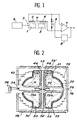
- a probe is thus seen comprising a first bottle 1 with positive polarization with its winding BF 2, a second bottle 3 with negative polarization with its winding BF 4, a single resonator HF 5 surrounding the two flasks and a generator HF 6 supplying this resonator.
- the two windings 2 and 4 are mounted in series-opposition and are connected to the positive and negative inputs of a differential amplifier 7, the output of which is looped back, via a level regulator referenced 8, to the windings BF , the looping takes place through a resistive balancing bridge 9.
- the frequency of the signal delivered by such an oscillator is equal to the nuclear resonance frequency, which is directly proportional to the ambient magnetic field, the proportionality factor being equal to the gyromagnetic ratio of the atomic nuclei.
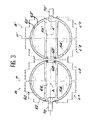
- Figure 2 illustrates in more detail the structure of such a probe and the shape of the BF windings. This embodiment is described in document FR-A-2 583 887.
- the probe comprises two bottles 20, 22 each consisting of a hemisphere and a cylindrical wafer. These two bottles are coated on the outside with a silver metallic layer, respectively 30 and 32, divided into non-contiguous sectors (to avoid circumferential eddy currents).
- the probe also comprises a central conductor formed by two half-sections 33a and 33b, the left end 34 of the section 33a being connected to the central core of a coaxial 36 and the right end 38 of the section 33b being connected to the conductive layer 32 of the bottle 22 by conductive strips 39.
- the conductive layer 32 of the bottle 22 is connected to the conductive layer 30 of the bottle 20 by conductive strips 39 'as described in application FR-A-2098624, each conductive strip connecting sectors belonging to separate bottles.
- sampling and excitation windings of this probe comprise, on the one hand, two hemispherical windings 40 and 42 outside the resonator and, on the other hand, two flat coils 44 and 46 inside the resonator.
- the probe shown is completed by an external shield 48 formed by metal strips deposited on an insulating support.
- the resonant frequency of the resonator is granted by a non-magnetic capacitor 50 disposed between the sections 33a and 33b of the central conductor. This capacitor is accessible from the outside through an opening 52 made in the shield 48.
- Hemispherical windings 40 and 42 are obtained by winding on a spherical template and impregnation with a resin.
- the staircase shape presented by the external zones comes from the fact that the turns which would be located in these zones would participate little in the excitation and the sampling and have therefore been eliminated, which lightens the probe all the more.
- windings 40 and 42, on the one hand, 44 and 46, on the other hand, are wound and connected so that the useful signals are added and the parasitic signals are cut off, as explained in the documents cited above.
- the object of the present invention is precisely to remedy all of these drawbacks. To this end, it offers a very compact and symmetrical structure in which each bottle is placed in a resonator of its own, the whole being completely surrounded by the BF windings, which are arranged symmetrically face to face and connected together .
- a form of revolution is generated by a curve rotating around an axis. If the curve is a circle and the axis a diameter of this circle, we will get a spherical shape. If the curve is a square and the axis a diagonal of this square, we will get a double cone or biconical shape, if the axis is a median axis of the square we will get a cylindrical shape, etc ...
- the two blocks are arranged end to end, Their axes being merged.
- the two blocks are arranged side by side, their axes being parallel.
- the two bottles can contain the same radical solution, the two resonators associated with these two bottles then having to resonate on two different frequencies corresponding respectively to a positive polarization for one of the solutions and to a negative polarization for the other.
- the two bottles can contain different radical solutions, the two resonators associated with these two bottles resonating on the same frequency corresponding to a positive polarization for one of the solutions and to a negative polarization for the other.
- the first solution can be used in the two bottles provided that one of the resonators is set at 57.6 MHz and the other at 58.9 MHz.
- the second solution may be suitable in the two bottles provided that one of the resonators is set at 58.9 MHz and the other at 60.5 MHz.
- the first solution can be used in one of the bottles and the second in the other, the two resonators being tuned to 58.9 MHz.
- the windings are connected in series-opposition.
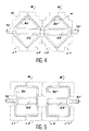
- Block B (B ′) comprises a spherical bottle 60 (60 ′), for example made of glass or pyrex, coated on its outer face with a metallic layer 62 (62 '), for example in silver, divided into sectors.
- This bottle contains a 64 (64 ') liquid sample.
- the bottle has a central channel crossed by an electrical conductor 66 (66 ') which forms, with the outer conductive layer 62 (62'), a resonator. This is supplied with high frequency energy by a coaxial cable 70 (70 ') connected to a high frequency generator not shown.
- Tuning capacitors 68 (68 ') are provided between the end of the central conductors and the outer metal layer.
- Each bottle is thus of revolution about an axis A and is, moreover, symmetrical with respect to a plane P (P ') perpendicular to this axis.
- Each bottle is arranged, by construction, inside a resonator which is specific to it (whereas in the prior art as illustrated in FIG. 2, the two bottles shared the same resonator).
- This resonator has the same symmetries (of revolution with respect to the axis A and with respect to a plane) as the bottle.
- the set of low frequency windings consists of a double coil L1, L2 (L'1, L'2) completely surrounding the bottle and the resonator.
- the two windings of each set are placed face to face, symmetrically with respect to the plane of symmetry P (P ') of the block. Electrically speaking, these windings are not necessarily identical, as will be better understood later, one may have fewer turns than the other and use a wire of smaller diameter than the other.
- windings can be connected in series-opposition, that is to say that the current which crosses them flows in opposite direction in the two windings (as opposed to a series-series arrangement where the currents would flow in the same direction).
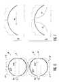
- Figure 4 shows another embodiment in which the bottle 80 (80 ′) and the external conductor of the resonator have a toric shape of triangular section.
- the advantage of this form is that we can play on the isotropy of the probe by choosing a suitable value for the angle ⁇ of the bottle ( Figure 4).
- FIG. 5 shows yet another exemplary embodiment in which the bottles and the external conductor of the resonator have a cylindrical shape.
- FIG. 6 shows a variant in which the two blocks B and B ′, instead of being placed end to end as in FIGS. 3 to 5, are placed side by side, their axes A and A ′ being parallel.
- FIG. 7 highlights the advantage of the series-opposition connection of the two windings relating to the same bottle.
- part (a) of FIG. 7 it has been assumed that the two windings were connected in series-series. Consequently, the assembly behaves as a single coil and the lines H of the detection field are parallel to the axis. If the field to be measured also comes to be parallel to this axis, no area of the sample will be subjected to a sampling field not parallel to the field to be measured (which is the necessary condition for the operation of a probe. to NMR). There will therefore be a prohibited axis of measurement for the probe: the very axis of the latter.
- the series-series assembly can be advantageous in the case where the probe is fixed and orientable relative to the field so as to place the probe along an axis perpendicular to the prohibited axis.
- This particular assembly makes it possible to have an amplitude of the larger output signal.
- Opposite windings L1, L′1 include 1900 turns of wire of 0.40 mm diameter and the joined windings L2, L′2 have 1325 turns of 0.475 mm.
- the measurement signal is 4.34 while with a field perpendicular to the axis the signal is 4.49; the anistropia fell to 3%.
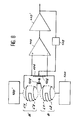
- FIG. 8 shows the diagram of the mounting in oscillator of a probe according to the invention.
- the windings L1, L2 of block B as well as the windings L′1, L′2 of block B ′ are mounted for example in series-opposition in each block, as already explained.
- the two double coils (L1, L2), (L′1, L′2) are themselves mounted in series-opposition through a resistor 102 connected to ground at its midpoint.
- the free ends of the two double coils are connected through a resistance bridge 104, 106.
- This bridge is, moreover, connected to the inputs of a linear differential amplifier 110 possibly followed by another amplifier 110 ′; the amplified output is looped back to the bridge 104, 106 at an adjustable point allowing balancing to be obtained.
- Two HF generators 100 and 100 ′ supply the two independent resonators of the two blocks.
- the amplified output constitutes the output S of the probe.
- the frequency of the signal available on S is directly proportional to the intensity
Landscapes
- Physics & Mathematics (AREA)
- Condensed Matter Physics & Semiconductors (AREA)
- General Physics & Mathematics (AREA)
- Magnetic Resonance Imaging Apparatus (AREA)
- Investigating Or Analyzing Materials By The Use Of Magnetic Means (AREA)
- Lasers (AREA)
- Investigating Or Analysing Materials By Optical Means (AREA)
Claims (10)
- Sonde für die magnetische Kernresonanz, die wenigstens zwei Fläschchen (60, 60'; 80, 80'; 90, 90') für radikalische Lösungen - eines (60; 80; 90) für positive Kernpolarisation, das andere (60'; 80', 90') für negative Kernpolarisation -, einen Hochfrequenz-Koaxialresonator (62, 66; 62', 66') sowie, um diese Fläschchen (60, 60'; 80, 80'; 90, 90') herum, Anordnungen von Wicklungen zur Anregung und Signalentnahme bei niedriger Frequenz (L1, L2; L'1, L'2), wobei diese Anordnungen gegenphasig in Serie geschaltet sind, und einen Verstärker (110) mit zwei Eingängen, die mit den Anordnungen von Wicklungen verbunden sind, und mit einem Ausgang, der auf genannte Anordnungen von Wicklungen zurückgeschleift ist, umfaßt, wobei ein Fläschchen (60, 60'; 80, 80'; 90, 90') und seine Anordnung von Wicklungen zur Anregung und Signalentnahme (L1, L2; L'1, L'2) jeweils einen Block (B, B') bildet, der eine Drehsymmetrie in Bezug auf eine Achse (A, A') hat, wobei diese Sonde dadurch gekennzeichnet ist, daß- jeder Block (B, B') ferner eine Symmetrie in Bezug auf eine zur Drehachse senkrechte Ebene (P, P') besitzt,- um jedes Fläschchen herum ein Hochfrequenz-Koaxialresonator (62, 66), (62', 66') angebracht ist, der eine Drehsymmetrie um die Achse und eine Symmetrie in Bezug auf genannte, zur Drehachse senkrechte Ebene (P, P') besitzt,- jede Anordnung von Wicklungen zur Anregung und Signalentnahme (L1, L2), (L'1, L'2) vollständig den Resonator und das Fläschchen umgibt und aus zwei Drehwicklungen (L1, L2), (L'1, L'2) zusammengesetzt ist, die auf beiden Seiten genannter Ebene (P, P') einander gegenüber angeordnet sind, wobei diese beiden Wicklungen miteinander verbunden sind.
- Sonde nach Anspruch 1, durch die Tatsache gekennzeichnet, daß die Drehungsform der Blöcke (B, B'), Fläschchen (60, 60'), Resonatoren (62, 66; 62', 66'), zwei Wicklungen (L1, L2), (L'1, L'2) sphärisch ist.
- Sonde nach Anspruch 1, durch die Tatsache gekennzeichnet, daß die Drehungsform der Blöcke (B, B'), Fläschchen (80, 80'), Resonatoren (62, 66; 62', 66'), zwei Wicklungen (L1, L2), (L'1, L'2) bikonisch ist.
- Sonde nach Anspruch 1, durch die Tatsache gekennzeichnet, daß die Drehungsform der Blöcke (B, B'), Fläschchen (90, 90'), Resonatoren (62, 66; 62', 66'), zwei Wicklungen (L1, L2), (L'1, L'2) zylindrisch ist.
- Sonde nach Anspruch 1, durch die Tatsache gekennzeichnet, daß die zwei Blöcke (B, B') Spitze an Spitze angeordnet sind, wobei ihre Achsen zusammenfallen.
- Sonde nach Anspruch 1, durch die Tatsache gekennzeichnet, daß die zwei Blöcke (B, B') Seite an Seite angeordnet sind, wobei ihre Achsen parallel sind.
- Sonde nach Anspruch 1, durch die Tatsache gekennzeichnet, daß die zwei Fläschchen (60, 60'; 80, 80'; 90, 90') dieselbe radikalische Lösung (64, 64') enthalten, wobei die zwei den Fläschchen (60, 60'; 80, 80'; 90, 90') zugeordneten Resonatoren (62, 66; 62', 66') mit zwei unterschiedlichen Frequenzen schwingen, die einer positiven Kernpolarisation für die eine der Lösungen beziehungsweise einer negativen Kernpolarisation für die andere entsprechen.
- Sonde nach Anspruch 1, durch die Tatsache gekennzeichnet, daß die zwei Fläschchen (60, 60'; 80, 80'; 90, 90') verschiedene radikalische Lösungen enthalten, wobei die zwei den Fläschchen (60, 60'; 80, 80', 90, 90') zugeordneten Resonatoren (62, 66; 62', 66') mit gleicher Frequenz schwingen, die einer positiven Kernpolarisation für die eine der Lösungen und einer negativen Kernpolarisation für die andere entspricht.
- Sonde nach Anspruch 1, durch die Tatsache gekennzeichnet, daß die zwei Wicklungen (L1, L2), (L'1, L'2) ein und desselben Blocks (B, B') miteinander gegenphasig in Serie verbunden sind.
- Sonde nach Anspruch 1, durch die Tatsache gekennzeichnet, daß die zwei Wicklungen (L1, L2), (L'1, L'2) ein und desselben Blocks verschiedene Windungszahlen haben.
Applications Claiming Priority (2)
| Application Number | Priority Date | Filing Date | Title |
|---|---|---|---|
| FR9004323 | 1990-04-04 | ||
| FR9004323A FR2660760B1 (fr) | 1990-04-04 | 1990-04-04 | Sonde a rmn compacte. |
Publications (2)
| Publication Number | Publication Date |
|---|---|
| EP0451054A1 EP0451054A1 (de) | 1991-10-09 |
| EP0451054B1 true EP0451054B1 (de) | 1993-11-10 |
Family
ID=9395448
Family Applications (1)
| Application Number | Title | Priority Date | Filing Date |
|---|---|---|---|
| EP91400908A Expired - Lifetime EP0451054B1 (de) | 1990-04-04 | 1991-04-03 | Kompakte Sonde für die magnetische Kernresonanz |
Country Status (6)
| Country | Link |
|---|---|
| US (1) | US5198767A (de) |
| EP (1) | EP0451054B1 (de) |
| CA (1) | CA2039539C (de) |
| DE (1) | DE69100611T2 (de) |
| FR (1) | FR2660760B1 (de) |
| NO (1) | NO302847B1 (de) |
Families Citing this family (8)
| Publication number | Priority date | Publication date | Assignee | Title |
|---|---|---|---|---|
| FR2695484B1 (fr) * | 1992-09-07 | 1994-10-14 | Commissariat Energie Atomique | Sonde de magnétomètre à RMN à un seul résonateur et à solution radicalaire unique. |
| FR2707014B1 (de) * | 1993-06-24 | 1995-09-22 | Commissariat Energie Atomique | |
| US5451874A (en) * | 1993-08-05 | 1995-09-19 | Trw Inc. | Method and system for providing heterodyne pumping of magnetic resonance |
| EP0721137B1 (de) * | 1994-07-14 | 2004-01-21 | Seiko Epson Corporation | Stromversorgungsschaltung, flüssigkristallanzeigevorrichtung und elektronisches gerät |
| FR2742550B1 (fr) * | 1995-12-19 | 1998-01-16 | Commissariat Energie Atomique | Solution radicalaire pour magnetometre a resonance magnetique nucleaire |
| FR2757951B1 (fr) * | 1996-12-26 | 1999-01-29 | Commissariat Energie Atomique | Dispositif de reequilibrage automatique de bobinages d'un capteur |
| JP3569922B2 (ja) | 1997-03-28 | 2004-09-29 | セイコーエプソン株式会社 | 電源回路、表示装置及び電子機器 |
| KR20140119570A (ko) * | 2013-04-01 | 2014-10-10 | 한국전자통신연구원 | 자유 라디칼 측정 장치 및 그 방법 |
Family Cites Families (6)
| Publication number | Priority date | Publication date | Assignee | Title |
|---|---|---|---|---|
| FR1447226A (fr) * | 1965-04-22 | 1966-07-29 | Commissariat Energie Atomique | Magnétomètre à résonance magnétique nucléaire du type oscillateur à couplage de spin |
| FR2098624A5 (de) * | 1970-07-22 | 1972-03-10 | Commissariat Energie Atomique | |
| CA932801A (en) * | 1972-01-27 | 1973-08-28 | Canadian Patents And Development Limited | Dispersion type nuclear magnetic resonance magnetometer for weak field measurements |
| US3886440A (en) * | 1973-10-23 | 1975-05-27 | Geometrics | Proton precession magnetometer sensor |
| FR2583887B1 (fr) * | 1985-06-21 | 1987-07-31 | Commissariat Energie Atomique | Sonde de magnetometre a rmn a cavite accordable en son centre et a galette centrale dedoublee |
| FR2616551B1 (fr) * | 1987-06-11 | 1989-10-27 | Crouzet Sa | Magnetometre a resonance magnetique nucleaire |
-
1990
- 1990-04-04 FR FR9004323A patent/FR2660760B1/fr not_active Expired - Lifetime
-
1991
- 1991-04-02 US US07/679,449 patent/US5198767A/en not_active Expired - Lifetime
- 1991-04-02 CA CA002039539A patent/CA2039539C/en not_active Expired - Lifetime
- 1991-04-03 DE DE91400908T patent/DE69100611T2/de not_active Expired - Lifetime
- 1991-04-03 NO NO911306A patent/NO302847B1/no not_active IP Right Cessation
- 1991-04-03 EP EP91400908A patent/EP0451054B1/de not_active Expired - Lifetime
Also Published As
| Publication number | Publication date |
|---|---|
| CA2039539A1 (en) | 1991-10-05 |
| EP0451054A1 (de) | 1991-10-09 |
| US5198767A (en) | 1993-03-30 |
| DE69100611T2 (de) | 1994-05-11 |
| FR2660760B1 (fr) | 1992-06-19 |
| DE69100611D1 (de) | 1993-12-16 |
| NO911306D0 (no) | 1991-04-03 |
| CA2039539C (en) | 2000-07-04 |
| FR2660760A1 (fr) | 1991-10-11 |
| NO302847B1 (no) | 1998-04-27 |
| NO911306L (no) | 1991-10-07 |
Similar Documents
| Publication | Publication Date | Title |
|---|---|---|
| CA1278027C (fr) | Dispositif correcteur par elements magnetiques d'inhomogeneites duchamp magnetique dans un aimant | |
| CN113176526B (zh) | 基于三重谐振的光学谐振腔交变磁场传感系统及使用方法 | |
| EP0091351B1 (de) | Optisches Magnetometer | |
| CA1283950C (fr) | Magnetometre a helium pompe par laser | |
| EP1947469A1 (de) | Vorrichtung zur magnetischen Verstärkung, die mit einem Magnetempfänger mit Längswellensensiblität ausgestattet ist | |
| FR2710780A1 (fr) | Structures magnétiques ouvertes. | |
| EP0170558A1 (de) | Anordnung zum Erzeugen und/oder Empfangen von Wechselmagnetfeldern für mit magnetischer Kernresonanz arbeitende Apparate | |
| EP0451054B1 (de) | Kompakte Sonde für die magnetische Kernresonanz | |
| FR2517831A2 (fr) | Tete de mesure pour magnetometre et magnetometre comprenant une telle tete | |
| EP0445017B1 (de) | Koaxialer Resonator mit verteilter Abstimmkapazität | |
| EP0656545B1 (de) | Magnetometer mit polarisiertem Licht und gekoppeltem Hochfrequenzfeld | |
| EP3278128B1 (de) | Isolierter gleichstrom- und spannungssensor mit geringem übersprechen | |
| CA1292278C (fr) | Magnetometre a resonance magnetique nucleaire | |
| EP0206931B1 (de) | Magnetfeldmesssonde mittels magnetischer Kernresonanz abstimmbar auf den Mittelpunkt eines Hohlraumes mit geteilter Zentralscheibe | |
| CH499785A (fr) | Magnétomètre à résonance magnétique nucléaire du type oscillateur à couplage de spin | |
| Slocum et al. | Self‐Oscillating Magnetometer Utilizing Optically Pumped 4He | |
| FR2660074A1 (fr) | Magnetometre a blindage perfectionne. | |
| FR2624980A1 (fr) | Magnetometre vectoriel continu a capteur capacitif magnetostrictif et gradientmetre comportant application de ce capteur | |
| EP0587482A1 (de) | Magnetfeld-Messsonde mittels magnetischer Kernresonanz mit einem einzigen Resonator und einer einzigen radikalen Lösung | |
| EP0631150B1 (de) | Magnetische Kernresonanz-Sonde mit Oszillator-Regelkreis | |
| EP0136955A2 (de) | Anordnung zum Messen des Gradienten eines magnetischen Feldes durch magneto-optischen Effekt | |
| JP3031755B2 (ja) | 原子量3のHeソレノイド磁力計 | |
| EP0453544A1 (de) | Optisch gepumpte, atomare oder molekulare dämpfe enthaltende zelle und anwendung einer solchen zelle in einem magnetometer oder gyroskop | |
| FR2687478A1 (fr) | Dispositif de mesure d'un gradient de champ magnetique dont les erreurs de sensibilite et de desalignement sont minimisees. | |
| FR3058527A1 (fr) | Dispositif pour adapter un appareil de resonnance magnetique nucleaire a l'analyse de petits echantillons; procede associe |
Legal Events
| Date | Code | Title | Description |
|---|---|---|---|
| PUAI | Public reference made under article 153(3) epc to a published international application that has entered the european phase |
Free format text: ORIGINAL CODE: 0009012 |
|
| AK | Designated contracting states |
Kind code of ref document: A1 Designated state(s): BE DE FR GB IT NL SE |
|
| 17P | Request for examination filed |
Effective date: 19920311 |
|
| 17Q | First examination report despatched |
Effective date: 19920811 |
|
| GRAA | (expected) grant |
Free format text: ORIGINAL CODE: 0009210 |
|
| AK | Designated contracting states |
Kind code of ref document: B1 Designated state(s): BE DE FR GB IT NL SE |
|
| REF | Corresponds to: |
Ref document number: 69100611 Country of ref document: DE Date of ref document: 19931216 |
|
| ITF | It: translation for a ep patent filed | ||
| GBT | Gb: translation of ep patent filed (gb section 77(6)(a)/1977) |
Effective date: 19940119 |
|
| PLBE | No opposition filed within time limit |
Free format text: ORIGINAL CODE: 0009261 |
|
| STAA | Information on the status of an ep patent application or granted ep patent |
Free format text: STATUS: NO OPPOSITION FILED WITHIN TIME LIMIT |
|
| 26N | No opposition filed | ||
| EAL | Se: european patent in force in sweden |
Ref document number: 91400908.9 |
|
| PGFP | Annual fee paid to national office [announced via postgrant information from national office to epo] |
Ref country code: SE Payment date: 19990329 Year of fee payment: 9 |
|
| PGFP | Annual fee paid to national office [announced via postgrant information from national office to epo] |
Ref country code: BE Payment date: 19990331 Year of fee payment: 9 |
|
| PGFP | Annual fee paid to national office [announced via postgrant information from national office to epo] |
Ref country code: NL Payment date: 19990429 Year of fee payment: 9 |
|
| PG25 | Lapsed in a contracting state [announced via postgrant information from national office to epo] |
Ref country code: SE Free format text: LAPSE BECAUSE OF NON-PAYMENT OF DUE FEES Effective date: 20000404 |
|
| PG25 | Lapsed in a contracting state [announced via postgrant information from national office to epo] |
Ref country code: BE Free format text: LAPSE BECAUSE OF NON-PAYMENT OF DUE FEES Effective date: 20000430 |
|
| BERE | Be: lapsed |
Owner name: COMMISSARIAT A L'ENERGIE ATOMIQUE Effective date: 20000430 |
|
| PG25 | Lapsed in a contracting state [announced via postgrant information from national office to epo] |
Ref country code: NL Free format text: LAPSE BECAUSE OF NON-PAYMENT OF DUE FEES Effective date: 20001101 |
|
| EUG | Se: european patent has lapsed |
Ref document number: 91400908.9 |
|
| NLV4 | Nl: lapsed or anulled due to non-payment of the annual fee |
Effective date: 20001101 |
|
| REG | Reference to a national code |
Ref country code: GB Ref legal event code: IF02 |
|
| PGFP | Annual fee paid to national office [announced via postgrant information from national office to epo] |
Ref country code: FR Payment date: 20100506 Year of fee payment: 20 |
|
| PGFP | Annual fee paid to national office [announced via postgrant information from national office to epo] |
Ref country code: DE Payment date: 20100423 Year of fee payment: 20 Ref country code: IT Payment date: 20100426 Year of fee payment: 20 |
|
| PGFP | Annual fee paid to national office [announced via postgrant information from national office to epo] |
Ref country code: GB Payment date: 20100420 Year of fee payment: 20 |
|
| REG | Reference to a national code |
Ref country code: DE Ref legal event code: R071 Ref document number: 69100611 Country of ref document: DE |
|
| REG | Reference to a national code |
Ref country code: GB Ref legal event code: PE20 Expiry date: 20110402 |
|
| PG25 | Lapsed in a contracting state [announced via postgrant information from national office to epo] |
Ref country code: GB Free format text: LAPSE BECAUSE OF EXPIRATION OF PROTECTION Effective date: 20110402 |
|
| PG25 | Lapsed in a contracting state [announced via postgrant information from national office to epo] |
Ref country code: DE Free format text: LAPSE BECAUSE OF EXPIRATION OF PROTECTION Effective date: 20110403 |