EP0656545B1 - Magnetometer mit polarisiertem Licht und gekoppeltem Hochfrequenzfeld - Google Patents
Magnetometer mit polarisiertem Licht und gekoppeltem Hochfrequenzfeld Download PDFInfo
- Publication number
- EP0656545B1 EP0656545B1 EP94402724A EP94402724A EP0656545B1 EP 0656545 B1 EP0656545 B1 EP 0656545B1 EP 94402724 A EP94402724 A EP 94402724A EP 94402724 A EP94402724 A EP 94402724A EP 0656545 B1 EP0656545 B1 EP 0656545B1
- Authority
- EP
- European Patent Office
- Prior art keywords
- frequency
- field
- magnetometer
- cell
- polarizer
- Prior art date
- Legal status (The legal status is an assumption and is not a legal conclusion. Google has not performed a legal analysis and makes no representation as to the accuracy of the status listed.)
- Expired - Lifetime
Links
Images



Classifications
-
- G—PHYSICS
- G01—MEASURING; TESTING
- G01R—MEASURING ELECTRIC VARIABLES; MEASURING MAGNETIC VARIABLES
- G01R33/00—Arrangements or instruments for measuring magnetic variables
- G01R33/20—Arrangements or instruments for measuring magnetic variables involving magnetic resonance
- G01R33/24—Arrangements or instruments for measuring magnetic variables involving magnetic resonance for measuring direction or magnitude of magnetic fields or magnetic flux
- G01R33/26—Arrangements or instruments for measuring magnetic variables involving magnetic resonance for measuring direction or magnitude of magnetic fields or magnetic flux using optical pumping
Definitions
- the subject of the present invention is a light polarization field magnetometer coupled radio frequencies. She finds an application in the precise measurement of weak magnetic fields (typically in the range of 20 to 70 ⁇ T which corresponds values of the Earth's magnetic field).
- the magnetometer of the invention enters the category of so-called resonance magnetometers, of which can find a general description in the article by F. Hartman entitled “Resonance Magnetometers”, published in the journal IEEE Transactions on Magnetics, flight. MAG-8, n ° 1, March 1972, pp. 66-75.
- the excitement of magnetic resonance is obtained by a winding arranged around the substance used.
- the signal pickup resonance is effected either by another winding (electric variant) either by a light beam of pumping (optical variant).
- the document FR-A-2 663 430 describes a optically pumped magnetometer which is shown schematically in Figure 1.
- a cell 10, at least partially transparent, is filled with a gas 12, generally of helium, at a pressure of 1 to a few torrs.
- a light source 14 delivers a light beam 15 whose wavelength is around 1.1 ⁇ m. This beam passes through a rectilinear polarizer 16. The resulting polarized beam 17 passes through the cell 10 and emerges in the form of a bundle 18.
- a radio frequency discharge (called “weak” or “soft”) is produced in the gas 12 by a generator 30 connected to two electrodes 32, 33 arranged around the cell 10.
- This discharge produces atoms in a metastable being ( 2 3 S 1 in the case of helium).
- the incident light beam 17 "pumps” these atoms from the metastable state and brings them into another excited state (2 3 P).
- the energy levels are separated into sub-levels, called ZEEMAN.
- a resonance between such sub-levels can be established by a radiofrequency field.
- FIG. 1 This resonance is highlighted by various means known to those skilled in the art, including a variant is shown in Figure 1.
- This is a winding 20 arranged on either side of the cell 10 (in a so-called Helmoltz arrangement), a radiofrequency generator 22, of a photodetector 24 receiving the emergent light radiation 18, from a amplifier 25 connected to photodetector 24, of a synchronous detector 21 receiving a reference signal from generator 22 and an integrator 23.
- the generator 22 supplies the winding 20 with current at frequency F, which creates a field oscillating magnetic part of which maintains the resonance and modulates in return the light beam 18 having crossed cell 10. This modulation is found in the electrical signal delivered by the photodetector 24 and is detected by the detector synchronous 21.
- the signal delivered by the detector synchronous 21 has a component in phase with the reference signal, and this component serves as a signal error.
- the integrator 23 eliminates the error static. This error signal adjusts the frequency F of the frequency generator 22 to cancel the signal error.
- This generator must therefore be able to be controlled in tension. It can be for example an oscillator voltage controlled (V.C.O. for short for "Voltage Controlled Oscillator ").
- Magnetometers of this type have first used helium lamps.
- LNA lanthanum-neodymium aluminate
- magnetometers Although satisfactory in some respects, these magnetometers have drawbacks, however. Indeed, in principle, they are strongly anisotropic, and this in both amplitude and frequency. These anisotropies are either consequences of the cycle of optical pumping and intensity detection transmitted light, either related to the phenomenon of magnetic resonance.
- Document FR-A-2 663 430 proposes a solution to this problem. It consists in providing the means magnetometer for rotating the direction of polarization of the beam luminous 17 injected into cell 10, to give it the optimal direction corresponding to an amplitude maximum of the resonance signal.
- the magnetometer comprises a directional magnetometer, such as a set of three "flux-gate” or RPE magnetometer (Electronic Paramagnetic Resonance), to obtain information about the direction of the ambient field at measure.
- a circuit for processing this information calculates the optimal orientation of the polarization and therefore controls the rotation of the polarizer.
- the magnetometer includes means for modulating at low frequency the direction of polarization and to perform a synchronous detection of the resonance signal.
- the signal detected serves as an error signal to correct the polarization and give it the optimal direction.
- the polarization modulation variant has the disadvantage of reducing the band bandwidth of the magnetometer, since the maximum frequency of analysis is necessarily less than that of the modulation.
- This type of magnetometer is illustrated on the Figure 2 which includes means already shown on Figure 1 and which therefore bear the same references: this is cell 10 filled with gas 12, the laser 14 emitting a beam 15, the polarizer 16 delivering a beam with rectilinear polarization 17, the photodetector 24 receiving the emerging beam 18, of the frequency control circuit 21, of the radio frequency generator 22, frequency meter 26 and the discharge circuit 30.
- This magnetometer further comprises a first servo circuit 40 which controls the position angle ⁇ of the polarizer.
- the purpose of the present invention is to remedy the drawbacks which have been set out above. To this end, it provides a magnetometer without anisotropy (frequency or amplitude) and which does not does not use polarization modulation light or directional magnetometers associates. This result is obtained by enslaving direction of polarization of the light beam incident in a direction perpendicular to the field ambient magnetic Bo to be measured and simultaneously controlling the direction of the magnetic field radio frequency parallel to the direction of polarization. In other words, the management of polarization as well as that of the radiofrequency field both are facing in the same direction whatever the direction of the field magnetic to measure.
- the invention as defined above has the advantage of considerable simplicity compared to magnetometer described in document FR-A-2 663 430.
- any possible source of error related to either the coding of the angular rotation of the polarizer, and its transmission to the coils, as well as any other source, is eliminated. error causing phase variations on the detected signals.
- the polarizer and the means generating the radiofrequency field are integral with one another and the rotation of these elements is simultaneous; we are therefore sure that the same angle, preferably O °, will be kept between the direction of polarization, on the one hand, and the direction of the field B 1 radio frequency on the other hand.
- this magnetometer will be further characterized in that the synchronous detection circuit verifies that the amplitude (A 2 ) of the signal at the double frequency is not zero and in that the direction of rectilinear polarization of the beam is parallel to the direction of the radio frequency field.
- a magnetometer according to the invention will also be characterized in that the means generating radio frequencies consist of a single coil.
- the magnetometer according to the invention will characterized in that the means for rotating the whole polarizer-means to apply the field of radiofrequency are constituted by a motor piezoelectric.
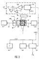
- a magnetometer according to a preferred embodiment of the invention is shown in Figure 3.
- This magnetometer includes means already shown in Figures 1 and 2 and which therefore bear the same references. These are the cell 10 filled with gas 12, the laser 14 emitting a beam 15, the polarizer 16 delivering a rectilinear polarized beam 17, the photodetector 24 receiving the emerging beam 18, the frequency control circuit 21, the radio frequency generator 22, frequency meter 26 and discharge circuit 30.
- the generator 22 controls the current induced in a coil 56 placed near the cell 12 so as to generate in the latter a radio frequency field B 1 .
- a rotary contact is used, for example a contact by capacitive coupling or by a transformer whose primary winding is fixed and the movable secondary winding.
- the coil and the polarizer are mounted so that the polarization P and the field B 1 are parallel.
- the coil-polarizer assembly is more precisely illustrated in Figure 4.
- the polarizer 16 is mounted in the center of a ring support 60, hollowed out in its central part.
- the coil 56 is mounted on a hollow cylinder 62. To join the two together, it suffices to mount the ring at the end of the cylinder, for example with non-magnetic screws.
- the signal detected by the photodetector 24 comprises, in addition to a DC component A O , two components A 1 and A 2 , respectively at the frequency of LARMOR and at the frequency twice that of LARMOR.
- each component A 1 and A 2 is complex and it is convenient to represent them by their component in phase and in phase quadrature with a reference signal V RF at the LARMOR frequency generated by the generator 22.
- V RF reference signal
- quadrature component has a central asymmetrical part and almost linear.
- One of the specifications of the magnetometer is that the measurement of the magnetic field must be independent of the orientation of the sensor relative to this field. It is therefore fundamental not to bring back any magnetic element or requiring DC power at proximity to the probe, since such components would generate during rotations of the probe magnetic signatures and therefore measurement errors of the terrestrial field whose importance would vary according to the arrangement of the magnetometer.
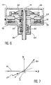
- the piezoelectric motor shown is illustrated in Figure 6. Operation of this type of engine is based on the exploitation of movements generated on the surface of a stator which present in the form of an "elastic" body excited in vibration. A rotor 66 pressed against the stator by the bias of a spring 68 is driven by friction by the stator.
- the entire engine 46 has was made with a hollow pin 70 to allow the transmission of the light beam through the device. Both rotor 66 and stator 64 are annulars and the mechanical support 16 and the means 56 excitation of the radiofrequency field, is secured to the motor via the axis of the latter.
- the mechanical support 60, 62 is thus rotated by motor 46, speed and direction control of rotation of the rotor 66 by means of electrical excitation applied to a transducer piezoelectric used to create on the surface of the stator 64 the progressive wave which is at the origin of angular movements of the rotor.
- the references 72 and 74 respectively represent a case and its cover, reference 76 a plate, the reference 78 a protective rubber.
- Axis 70 passes through a bearing 80.
- the assembly is between the spring 68 and a ceramic stop 82, the reference 84 representing a support ring and the reference 86 protection of the stop.
- the magnetometer comprises a circuit 40 for controlling the direction of the polarizer 16.
- This circuit comprises a first synchronous detection circuit 42 receiving the electrical signal delivered by the photodetector 24 and a reference voltage V RF coming from the generator 22.
- This circuit 42 detects the amplitude A 1q of the component in phase quadrature with the reference signal V RF .
- this amplitude A1q serves as an error signal, which, once amplified by an amplifier 44, supplies the motor 46 which rotates the polarizer 16 in a direction such that the signal error is canceled.
- the rotation of the polarizer 16 causes, due to the mechanical connection of the polarizer-coil, the rotation of the coil 56.
- FIG. 7 illustrates the function fulfilled by the servo-control 40.
- the directions are identified with respect to a system of Oxyz trirectangular axes.
- the light beam 17 is supposed to propagate along the axis Oy.
- the rectilinear polarization P of this beam is therefore located in the xOz plane.
- the ambient magnetic field B 0 is directed in any direction.
- the servo means 40 then have the function of giving the polarization the direction D 1 perpendicular to Bo.
- the radio frequency field B 1 is assumed to be oriented parallel to D1, due to the mechanical connection between the polarizer and the coil.
- B 1 is therefore also perpendicular to B 0 . It will be observed that, whatever the direction of B 0 , there is always a direction of the xOz plane which is perpendicular to B 0 . Now, it is certain that during a complete rotation of the polarizer 16, the direction of polarization P will pass through a 90 ° position from B 0 .
- the minimum angle that B 0 with a line from the xOz plane is equal to ( ⁇ / 2) - ⁇ n if ⁇ n designates the angle made by the normal to the xOz plane (in other words the Oy axis) with the field B 0 ; the maximum angle is equal to ( ⁇ / 2) + ⁇ n.
- the angle made by the direction of polarization P with B 0 will therefore vary between ( ⁇ / 2) - ⁇ n and ( ⁇ / 2) + ⁇ n. It will therefore necessarily go through ⁇ / 2.
- the signal detected by the photodetector 14 comprises, in addition to a continuous term A o , spectral components A 1 and A 2 respectively at the frequency of LARMOR and at the frequency twice that of LARMOR.
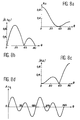
- FIGS. 8a to 8d show the variations of certain signals as a function of the angle ⁇ made by the direction of polarization with the direction of the magnetic field to be measured B 0 .
- Figure 8b shows the absolute value
- . It is canceled for ⁇ 0 and 90 ° and also for 54 °.
- Figure 8c shows the absolute value
- FIG. 8d shows the amplitude A 1q , in magnitude and in sign, which is the servo signal intended for the circuit 42.
- the polarization control is therefore carried out by verifying that two conditions are simultaneously satisfied, namely A 1q zero and A 2 greater than a certain threshold.
- This double function is ensured in circuit 40, for example by a comparator 41 which compares A 2 with a threshold s and by a logic gate Et 45 which delivers a control signal to the motor 46 only if A 2 is greater than the threshold.
- the circuit 21 can also deliver a signal reflecting the amplitude
Landscapes
- Physics & Mathematics (AREA)
- Condensed Matter Physics & Semiconductors (AREA)
- General Physics & Mathematics (AREA)
- Measuring Magnetic Variables (AREA)
Claims (4)
- Optisch gepumptes Resonanzmagnetometer, umfassend eine Zelle (10), gefüllt mit einem Gas (12), dessen Atome ein gyromagnetisches Verhältnis γ aufweisen, wobei diese Zelle in ein magnetisches Umgebungsfeld
B 0 eingetaucht ist, das das zu messende Feld ist, eine einen Lichtstrahl (15) aussendende Lichtquelle (14), einen Linearpolarisator (16), der von diesem Strahl (15) durchquert wird und diesem Strahl eine lineare Polarisation entsprechend einer ersten Richtung (D1) verleiht, wobei der linear polarisierte Strahl (17) anschließend die Zelle (10) durchquert, einen Photodetektor (24), der den Strahl (18) empfängt, nach erfolgter Durchquerung der Zelle (10), wobei dieser Photorezeptor (24) ein elektrisches Signal liefert, Einrichtungen (56), um auf die Zelle (10) ein Radiofrequenzfeld (B 1) anzuwenden, wobei dieses Feld eine zweite Richtung (D2) und eine bestimmte Frequenz hat, Einrichtungen (21, 22), um diese Frequenz auf die Larmor-Frequenz F=γBo zu regeln, eine Einrichtung (26), um diese Frequenz (F) zu messen, wobei die Amplitude des UmgebungsmagnetfeldsB 0 sich durch die Relation Bo=F/γ von der Frequenz (F) ableitet,
wobei dieses Magnetometer dadurch gekennzeichnet ist, dass es außerdem umfasst:mechanische Verbindungseinrichtungen, die die Einrichtungen (56) zur Anwendung des Radiofrequenzfelds (B 1) mit dem Polarisator (16) verbinden,Regeleinrichtungen (40), die auf die mechanischen Verbindungseinrichtungen wirken, wobei diese Einrichtungen eine Synchrondetektionsschaltung (42) umfassen, die das durch den Photodetektor (24) geliefertes elektrische Signal und ein Referenzsignal (VRF) mit der Frequenz F des Radiofrequenzfelds empfangen, wobei das elektrische Signal zwei Komponenten A1 und A2 mit jeweils der Larmorfrequenz und der doppelten Frequenz dieser Larmorfrequenz umfasst, diese Schaltung (42) die Amplitude |A1q| der Komponente A1 mit der Larmorfrequenz (F) detektiert, die zum Referenzsignal (VRF) um 90° phasenverschoben ist, wobei diese Amplitude dazu dient, Einrichtungen (46) zu steuern, um die mechanischen Verbindungseinrichtungen so zu drehen, dass infolgedessen der Polarisator (16) und die Einrichtungen (56) zur Anwendung des Radiofrequenzfeldes simultan gedreht werden. - Magnetometer nach Anspruch 1, dadurch gekennzeichnet, dass die Amplitude |A2| des Signals mit der doppelten Frequenz der Larmorfrequenz nicht gleich null ist, und dass die Richtung (D1) der Linearpolarisation des Strahls (15) parallel zu der Richtung (D2) des Radiofrequenzfelds (
B 1) ist. - Magnetometer nach einem der Ansprüche 1 oder 2, dadurch gekennzeichnet, dass die Radiofrequenz-Erzeugungseinrichtungen (56) durch eine einzige Spule gebildet werden.
- Magnetometer nach einem der Ansprüche 1 bis 3, dadurch gekennzeichnet, dass die Einrichtungen (46) zum Drehen der Einheit aus Polarisator und Radiofrequenz-Erzeugungseinrichtungen (56) durch einen piezoelektrischen Motor gebildet werden.
Applications Claiming Priority (2)
| Application Number | Priority Date | Filing Date | Title |
|---|---|---|---|
| FR9314378A FR2713347B1 (fr) | 1993-12-01 | 1993-12-01 | Magnétomètre à polarisation lumineuse et à champ de radiofréquence couplés. |
| FR9314378 | 1993-12-01 |
Publications (2)
| Publication Number | Publication Date |
|---|---|
| EP0656545A1 EP0656545A1 (de) | 1995-06-07 |
| EP0656545B1 true EP0656545B1 (de) | 2002-01-30 |
Family
ID=9453416
Family Applications (1)
| Application Number | Title | Priority Date | Filing Date |
|---|---|---|---|
| EP94402724A Expired - Lifetime EP0656545B1 (de) | 1993-12-01 | 1994-11-29 | Magnetometer mit polarisiertem Licht und gekoppeltem Hochfrequenzfeld |
Country Status (5)
| Country | Link |
|---|---|
| US (1) | US5534776A (de) |
| EP (1) | EP0656545B1 (de) |
| CA (1) | CA2136145A1 (de) |
| DE (1) | DE69429763T2 (de) |
| FR (1) | FR2713347B1 (de) |
Cited By (1)
| Publication number | Priority date | Publication date | Assignee | Title |
|---|---|---|---|---|
| EP3115799A1 (de) | 2015-07-08 | 2017-01-11 | Commissariat à l'Energie Atomique et aux Energies Alternatives | Optisch-isotropes magnetometer |
Families Citing this family (13)
| Publication number | Priority date | Publication date | Assignee | Title |
|---|---|---|---|---|
| FR2815416B1 (fr) * | 2000-10-18 | 2002-12-13 | Commissariat Energie Atomique | Mesure vectorielle amelioree d'un champ magnetique |
| US7504827B1 (en) | 2001-11-14 | 2009-03-17 | Fonar Corporation | MRI test fixture |
| GB0515088D0 (en) * | 2005-07-22 | 2005-08-31 | Imerys Minerals Ltd | Particulate glass compositions and methods of production |
| US8281967B2 (en) * | 2007-09-14 | 2012-10-09 | Shape Corp. | Storage unit for truck beds |
| US8547090B2 (en) * | 2007-12-03 | 2013-10-01 | President And Fellows Of Harvard College | Electronic spin based enhancement of magnetometer sensitivity |
| FR2977326B1 (fr) | 2011-07-01 | 2013-08-09 | Commissariat Energie Atomique | Magnetometre vectoriel a haute resolution et de haute precision |
| JP6134092B2 (ja) | 2011-10-18 | 2017-05-24 | セイコーエプソン株式会社 | 磁場計測装置 |
| EP2817648B1 (de) * | 2012-02-22 | 2021-03-24 | Geometrics, Inc. | Quantenmechanische messvorrichtung |
| CN103852737B (zh) * | 2014-03-14 | 2017-09-29 | 武汉理工大学 | 一种优化的铯光泵弱磁检测装置 |
| FR3093360B1 (fr) | 2019-02-28 | 2021-03-19 | Commissariat Energie Atomique | Magnétomètre scalaire isotrope et tout optique |
| KR102104398B1 (ko) * | 2019-07-22 | 2020-04-24 | 국방과학연구소 | 원자 스핀 자이로스코프 및 이를 이용하여 자기장 기울기를 보정하는 방법 |
| CN111610470B (zh) * | 2020-05-09 | 2022-08-16 | 杭州电子科技大学 | 一种新型射频原子磁力仪及其实现方法 |
| IL300877A (en) * | 2023-02-22 | 2024-12-01 | Elta Systems Ltd | Light modulated optically pumped magnetometer system and method |
Family Cites Families (10)
| Publication number | Priority date | Publication date | Assignee | Title |
|---|---|---|---|---|
| NL274229A (de) * | 1961-02-02 | |||
| US4327327A (en) * | 1980-06-05 | 1982-04-27 | The Singer Company | All-angle gradient magnetometer |
| FR2598518B1 (fr) * | 1986-05-12 | 1988-06-24 | Centre Nat Rech Scient | Magnetometre a helium pompe par laser |
| US4780672A (en) * | 1987-04-30 | 1988-10-25 | Texas Instruments Incorporated | Laser driven helium magnetometers |
| FR2663430B1 (fr) * | 1990-06-14 | 1992-10-02 | Commissariat Energie Atomique | Magnetometre a resonance et a pompage optique utilisant un faisceau lumineux a polarisation asservie. |
| FR2663429B1 (fr) * | 1990-06-14 | 1992-09-11 | Commissariat Energie Atomique | Magnetometre a resonance et a pompage optique utilisant une polarisation sequentielle. |
| FR2663432B1 (fr) * | 1990-06-14 | 1992-09-11 | Commissariat Energie Atomique | Magnetometre a resonance et a pompage optique utilisant une pluralite de faisceaux multiplexes. |
| FR2668862A1 (fr) * | 1990-11-07 | 1992-05-07 | Centre Nat Rech Scient | Procede de determination de l'amplitude d'un champ magnetique par pompage optique par laser et magnetometre pour la mise en óoeuvre du procede. |
| US5227722A (en) * | 1991-04-08 | 1993-07-13 | Cae Electronics Ltd. | Dead-zone free optically pumped MZ magnetometer |
| FR2693801B1 (fr) * | 1992-07-16 | 1994-09-02 | Commissariat Energie Atomique | Magnétomètre à polarisation lumineuse et à champ de radiofréquence asservis. |
-
1993
- 1993-12-01 FR FR9314378A patent/FR2713347B1/fr not_active Expired - Fee Related
-
1994
- 1994-11-17 CA CA002136145A patent/CA2136145A1/en not_active Abandoned
- 1994-11-23 US US08/347,244 patent/US5534776A/en not_active Expired - Lifetime
- 1994-11-29 DE DE69429763T patent/DE69429763T2/de not_active Expired - Lifetime
- 1994-11-29 EP EP94402724A patent/EP0656545B1/de not_active Expired - Lifetime
Cited By (2)
| Publication number | Priority date | Publication date | Assignee | Title |
|---|---|---|---|---|
| EP3115799A1 (de) | 2015-07-08 | 2017-01-11 | Commissariat à l'Energie Atomique et aux Energies Alternatives | Optisch-isotropes magnetometer |
| US10371764B2 (en) | 2015-07-08 | 2019-08-06 | Commissariat A L'energie Atomique Et Aux Energies Alternatives | All-optical and isotropic magnetometer |
Also Published As
| Publication number | Publication date |
|---|---|
| DE69429763D1 (de) | 2002-03-14 |
| DE69429763T2 (de) | 2002-08-22 |
| US5534776A (en) | 1996-07-09 |
| FR2713347A1 (fr) | 1995-06-09 |
| FR2713347B1 (fr) | 1995-12-29 |
| EP0656545A1 (de) | 1995-06-07 |
| CA2136145A1 (en) | 1995-06-02 |
Similar Documents
| Publication | Publication Date | Title |
|---|---|---|
| EP0462000B1 (de) | Optisch gepumptes Resonanz-Magnetometer mit Verwendung einer Vielzahl von geschalteten Strahlen | |
| EP0462002B1 (de) | Resonanzmagnetometer mit optischen Pumpen, das unterschiedliche Polarisationszustände verwendet | |
| EP2795354B1 (de) | Isotropes magnetometer mit integriertem optischem pumpen | |
| EP0656545A1 (de) | Magnetometer mit polarisiertem Licht und gekoppeltem Hochfrequenzfeld | |
| CA1283950C (fr) | Magnetometre a helium pompe par laser | |
| EP0081412A2 (de) | Messkopf für Magnetometer | |
| EP3730959A1 (de) | Magnetometer gesteuert bei feldstärke null mit niedrigfrequenzfilterung des kompensationsfelds | |
| EP0579537B1 (de) | Magnetometer mit polarisiertem Licht und gesteuertem Hochfrequenzfeld | |
| EP0461999B1 (de) | Optisch gepumpter Resonanzmagnetometer mit optischem Strahl mit gesteuerter Polarisation | |
| EP0462001B1 (de) | Magnetometer mittels magnetischer Resonanz und mit Multiplex-Erregerwicklungen | |
| EP2541268B1 (de) | Hochauflösender vektorieller Hochpräzisionsmagnetometer | |
| WO2007144546A1 (fr) | Sonde electro-optique de mesure de temperature et de champ electromagnetique | |
| FR2779530A1 (fr) | Dispositif de mesure des composantes d'un champ magnetique a l'aide d'un magnetometre scalaire | |
| EP3702797B1 (de) | Isotropes, skalares und rein optisches magnetometer | |
| EP0136955B1 (de) | Anordnung zum Messen des Gradienten eines magnetischen Feldes durch magneto-optischen Effekt | |
| EP4075156A1 (de) | Verfahren zum betrieb eines optisch gepumpten nullfeld-magnetometers, das in einem umgebungsfeld ungleich null betrieben wird | |
| EP3961236B1 (de) | Elliptisch polarisiertes magnetometer mit zwei hochfrequenz-feldkomponenten zur detektion der parametrischen absorptionsresonanz | |
| EP3671248A1 (de) | Magnetometer mit optischer pumpfunktion eines sensiblen elements mit einem linear polarisierten licht und mehrweg-durchgang in dem sensiblen element | |
| FR3088729A1 (fr) | Magnetometre en alignement a decalage angulaire entre polarisations des faisceaux de pompe et de sonde | |
| FR2894663A1 (fr) | Gyrolaser a etat solide active optiquement par biais alternatif | |
| EP0616228A1 (de) | Mehrachsiger Resonanz-Magnetometer | |
| FR2668862A1 (fr) | Procede de determination de l'amplitude d'un champ magnetique par pompage optique par laser et magnetometre pour la mise en óoeuvre du procede. |
Legal Events
| Date | Code | Title | Description |
|---|---|---|---|
| PUAI | Public reference made under article 153(3) epc to a published international application that has entered the european phase |
Free format text: ORIGINAL CODE: 0009012 |
|
| AK | Designated contracting states |
Kind code of ref document: A1 Designated state(s): DE GB IT |
|
| 17P | Request for examination filed |
Effective date: 19951113 |
|
| 17Q | First examination report despatched |
Effective date: 20000405 |
|
| GRAG | Despatch of communication of intention to grant |
Free format text: ORIGINAL CODE: EPIDOS AGRA |
|
| GRAG | Despatch of communication of intention to grant |
Free format text: ORIGINAL CODE: EPIDOS AGRA |
|
| GRAH | Despatch of communication of intention to grant a patent |
Free format text: ORIGINAL CODE: EPIDOS IGRA |
|
| GRAH | Despatch of communication of intention to grant a patent |
Free format text: ORIGINAL CODE: EPIDOS IGRA |
|
| GRAA | (expected) grant |
Free format text: ORIGINAL CODE: 0009210 |
|
| REG | Reference to a national code |
Ref country code: GB Ref legal event code: IF02 |
|
| AK | Designated contracting states |
Kind code of ref document: B1 Designated state(s): DE GB IT |
|
| REF | Corresponds to: |
Ref document number: 69429763 Country of ref document: DE Date of ref document: 20020314 |
|
| GBT | Gb: translation of ep patent filed (gb section 77(6)(a)/1977) |
Effective date: 20020416 |
|
| PLBE | No opposition filed within time limit |
Free format text: ORIGINAL CODE: 0009261 |
|
| STAA | Information on the status of an ep patent application or granted ep patent |
Free format text: STATUS: NO OPPOSITION FILED WITHIN TIME LIMIT |
|
| 26N | No opposition filed | ||
| PGFP | Annual fee paid to national office [announced via postgrant information from national office to epo] |
Ref country code: DE Payment date: 20091120 Year of fee payment: 16 |
|
| PGFP | Annual fee paid to national office [announced via postgrant information from national office to epo] |
Ref country code: IT Payment date: 20091121 Year of fee payment: 16 Ref country code: GB Payment date: 20091119 Year of fee payment: 16 |
|
| GBPC | Gb: european patent ceased through non-payment of renewal fee |
Effective date: 20101129 |
|
| PG25 | Lapsed in a contracting state [announced via postgrant information from national office to epo] |
Ref country code: DE Free format text: LAPSE BECAUSE OF NON-PAYMENT OF DUE FEES Effective date: 20110531 |
|
| REG | Reference to a national code |
Ref country code: DE Ref legal event code: R119 Ref document number: 69429763 Country of ref document: DE Effective date: 20110601 Ref country code: DE Ref legal event code: R119 Ref document number: 69429763 Country of ref document: DE Effective date: 20110531 |
|
| PG25 | Lapsed in a contracting state [announced via postgrant information from national office to epo] |
Ref country code: GB Free format text: LAPSE BECAUSE OF NON-PAYMENT OF DUE FEES Effective date: 20101129 |
|
| PG25 | Lapsed in a contracting state [announced via postgrant information from national office to epo] |
Ref country code: IT Free format text: LAPSE BECAUSE OF NON-PAYMENT OF DUE FEES Effective date: 20101129 |