EP0451058B1 - Verfahren und Vorrichtung zum Ablegen eines Steigrohres in einem Zugangsbohrloch einer Salzkaverne für Gasspeicherung - Google Patents
Verfahren und Vorrichtung zum Ablegen eines Steigrohres in einem Zugangsbohrloch einer Salzkaverne für Gasspeicherung Download PDFInfo
- Publication number
- EP0451058B1 EP0451058B1 EP19910400921 EP91400921A EP0451058B1 EP 0451058 B1 EP0451058 B1 EP 0451058B1 EP 19910400921 EP19910400921 EP 19910400921 EP 91400921 A EP91400921 A EP 91400921A EP 0451058 B1 EP0451058 B1 EP 0451058B1
- Authority
- EP
- European Patent Office
- Prior art keywords
- cutting
- tool
- tubing
- tubular body
- piston
- Prior art date
- Legal status (The legal status is an assumption and is not a legal conclusion. Google has not performed a legal analysis and makes no representation as to the accuracy of the status listed.)
- Expired - Lifetime
Links
Images


Classifications
-
- E—FIXED CONSTRUCTIONS
- E21—EARTH OR ROCK DRILLING; MINING
- E21B—EARTH OR ROCK DRILLING; OBTAINING OIL, GAS, WATER, SOLUBLE OR MELTABLE MATERIALS OR A SLURRY OF MINERALS FROM WELLS
- E21B23/00—Apparatus for displacing, setting, locking, releasing or removing tools, packers or the like in boreholes or wells
- E21B23/004—Indexing systems for guiding relative movement between telescoping parts of downhole tools
- E21B23/006—"J-slot" systems, i.e. lug and slot indexing mechanisms
-
- B—PERFORMING OPERATIONS; TRANSPORTING
- B65—CONVEYING; PACKING; STORING; HANDLING THIN OR FILAMENTARY MATERIAL
- B65G—TRANSPORT OR STORAGE DEVICES, e.g. CONVEYORS FOR LOADING OR TIPPING, SHOP CONVEYOR SYSTEMS OR PNEUMATIC TUBE CONVEYORS
- B65G5/00—Storing fluids in natural or artificial cavities or chambers in the earth
-
- E—FIXED CONSTRUCTIONS
- E21—EARTH OR ROCK DRILLING; MINING
- E21B—EARTH OR ROCK DRILLING; OBTAINING OIL, GAS, WATER, SOLUBLE OR MELTABLE MATERIALS OR A SLURRY OF MINERALS FROM WELLS
- E21B29/00—Cutting or destroying pipes, packers, plugs or wire lines, located in boreholes or wells, e.g. cutting of damaged pipes, of windows; Deforming of pipes in boreholes or wells; Reconditioning of well casings while in the ground
- E21B29/002—Cutting, e.g. milling, a pipe with a cutter rotating along the circumference of the pipe
- E21B29/005—Cutting, e.g. milling, a pipe with a cutter rotating along the circumference of the pipe with a radially-expansible cutter rotating inside the pipe, e.g. for cutting an annular window
-
- E—FIXED CONSTRUCTIONS
- E21—EARTH OR ROCK DRILLING; MINING
- E21B—EARTH OR ROCK DRILLING; OBTAINING OIL, GAS, WATER, SOLUBLE OR MELTABLE MATERIALS OR A SLURRY OF MINERALS FROM WELLS
- E21B31/00—Fishing for or freeing objects in boreholes or wells
- E21B31/12—Grappling tools, e.g. tongs or grabs
- E21B31/16—Grappling tools, e.g. tongs or grabs combined with cutting or destroying means
-
- E—FIXED CONSTRUCTIONS
- E21—EARTH OR ROCK DRILLING; MINING
- E21B—EARTH OR ROCK DRILLING; OBTAINING OIL, GAS, WATER, SOLUBLE OR MELTABLE MATERIALS OR A SLURRY OF MINERALS FROM WELLS
- E21B31/00—Fishing for or freeing objects in boreholes or wells
- E21B31/12—Grappling tools, e.g. tongs or grabs
- E21B31/20—Grappling tools, e.g. tongs or grabs gripping internally, e.g. fishing spears
Definitions
- the invention relates to a method for eliminating casing disposed coaxially inside a casing in an access well to a saline gas storage cavity.
- the invention also relates to a device making it possible to implement this method.
- underground reservoirs In order to ensure the supply of natural gas to regions without deposits large enough to meet demand, natural gas from other regions is increasingly stored in underground reservoirs.
- underground reservoirs can be constituted either by porous rocks in which the gas, injected under pressure, drives out the water which initially occupied the rock, or by salt cavities dug in a saliferous solid mass by injection of fresh water under pressure. In the latter case, the gas injected under pressure drives out the brine resulting from the dissolution of the salt in the water.
- each well 10 is internally equipped with a retaining casing 12.
- An operating casing 14 is lowered coaxially inside the retaining casing 12 and the annular space formed between the two casings is closed at its lower end by a sealing system 16.
- a casing 18 is then lowered into the well, coaxial with the casings 12 and 14, in order to allow the injection of fresh water under pressure into the salt mass. This injection is carried out in stages, in order to gradually increase the volume of salt dissolved in the form of brine 19, which defines the volume of the storage cavity 21 obtained.
- the natural gas which it is desired to store is then injected under pressure through the annular passage formed between the casing 14 and the casing 18.
- the gas 23 thus injected drives out the brine 19 through the casing 18.
- the gas thus gradually replaces the brine inside the cavity 21 and it can be compressed there to a value of approximately 240 bars.
- the storage cavity thus formed is then exploited, as illustrated in FIG. 2, by withdrawals and gas injections which are carried out both through the annular space formed between the casing 14 and the casing 18 and by inside the latter.
- the lower end of the casing 18 which is located near the bottom of the cavity is closed by a sealing system 20.
- a circulation valve 22 formed in the casing 18 below the system of sealing 20 and safety valves 24 located at the top of the casing 18 are open.
- a tool for cutting casing, a casing or a drill rod from the inside is marketed by the Company Bowen Tools Inc ..
- This tool is designed to be mounted at the lower end of a drill string which is lowered into the well. It mainly consists of a central mandrel supporting from bottom to top of the pads or leaf springs permanently applied elastically against the inner surface of the cutting tube, radially movable anchors and knives also radially movable.
- the anchoring parts are capable of sliding radially on a sleeve carrying the pads and which cooperates with the mandrel by means of a unidirectional thread preventing any assembly of the sleeve on the mandrel as long as the latter is not rotated in the screwing direction, while allowing a downward translation of the sleeve on the mandrel when a relative force is exerted axially in this direction between the two parts.
- a piece provided with ramps at each of its ends is further placed on the mandrel between the anchoring pieces and the knives, so that a rise of the sheath on the mandrel successively has the effect of spreading the pieces of anchoring to the inner wall of the tube and then, when these parts are anchored against the wall, to spread the knives.
- this cutting tool is obtained by rotating the mandrel in the screwing direction, which normally has the consequence of lowering it relative to the sheath which remains immobilized in the tube thanks to the pads which it supports.
- This descent of the mandrel has the effect, firstly, of firmly anchoring the tool in the tube by means of the anchoring parts.
- the sleeve is no longer in engagement with the mandrel by means of the unidirectional thread and the cutting of the tube is carried out by continuing the rotation of the mandrel and by exerting on it a downward force, which has the consequence of spreading the knives.
- a cutting tool of this type is not suitable for the removal of casing placed in an access well to a saline cavity.
- the weight of the cut section acting on the anchoring parts would have the immediate effect of moving them down as well as the sheath which supports them and, consequently, dropping the stretch. This is not acceptable because the casing could be seriously damaged and even punctured during the fall (the length of the casings is generally between 1400 m and 1700 m).
- the invention specifically relates to a method and a device for eliminating the tubing for access to a saline cavity in order to very significantly increase the rate of withdrawal of the gas contained in this saline cavity, this method and this device being particularly reliable, eliminating any risk of damaging the casing which surrounds the casing, and taking into account the various imperatives linked in particular to the dimensional characteristics of the wells, cavities, casing and casing, to the pressure conditions prevailing in the well and to the need to leave in place the safety valves located at the top of the casing.
- the anchoring means are operated independently of the cutting means, so that they can be effectively and securely held in engagement when the cutting of a section is completed, which allows the descent of this section using the tool up '' below the lower end of the casing.
- the anchoring means comprise a piston movable along an axis of the tool in said lower part, an upper face of the piston being subjected to the pressure prevailing inside the train of rods and a lower face of the piston being subjected to the action of said return means, the piston being integral with at least one corner cooperating with at least one anchoring part to move the latter radially outwards, at the against elastic means, when the piston moves upwards.
- the return means then advantageously comprise a closed chamber formed in said lower part and filled with gas under pressure.
- this gas can in particular be nitrogen, which must be compressed before the tool is lowered into the well at a pressure, for example around 220 bars, at least 50 bars higher than the pressure maximum that can be reached at the lower end of the casing (for example, about 170 bar).
- a sliding rod is preferably mounted in the piston, so as to be able to occupy a high position, in which this rod closes a passage formed in the piston and capable of bringing the lower and upper faces of the latter into communication, and a low position in which said passage is open, the sliding rod being normally held in the high position by a frangible member.
- Additional redundancy can also be obtained by suspending the cutting tool from the train of tubular rods by disconnection means which can be operated remotely.
- These disconnection means can in particular comprise, in the preferred embodiment of the invention, a male tubular body fixed to the lower end of the train of tubular rods, and comprising flexible branches provided externally with imprints of formed imprints in a female tubular body fixed to the rotary upper part of the cutting tool, a retaining sleeve normally immobilized in the high position in the male tubular body by blocking means then maintaining the imprints formed on the flexible branches engaged with the imprints formed in the female tubular body, an unlocking of the locking means controlled by the application of a downward force on the retaining sleeve bringing the latter into a low position in which the flexible branches can deform radially towards the interior to release the imprints formed on these branches from the imprints formed on the c female tubular orps.
- the anchoring means may have to be actuated, then released for relatively long periods, after the cutting of a section of tubing located close to the ground (for example at a depth of 100 m), since this section must then be lowered by the tool to the bottom of the well (for example at 1700 m deep). Maintaining sufficient pressure in the drill string to ensure the loosening of the anchoring means throughout the ascent of the tool then poses problems which are difficult to solve, being given that the elementary rods of the drill string must be dismantled during this ascent.
- the piston advantageously supports a rotary barrel provided with a groove into which penetrates at least one pin carried by the lower, non-rotating part of the tool, this groove being such that each time that a pressure pulse is sent inside the drill string, the anchoring means pass from their retracted position to their anchoring position, and vice versa, and remain in this position as long as a new pressure pulse does not is not sent to the drill string.
- the upper rotary part of the latter is normally engaged with the lower non-rotary part by a unidirectional thread allowing a downward movement of said upper part, under the effect of a rotation of the latter, to a lower cutting position in which said thread is no longer engaged, and an upward movement of said upper part, by a simple translation of the latter.
- the knife is supported on a ramp formed on a part mounted to slide along the axis of the tool and the opposite end of which bears on the lower non-rotating part, by means of an elastic means. prestressed.
- a cutting tool in order to eliminate the casing 18 over its entire length, with the exception of the upper part of approximately 100 m in which the safety valves 24 are located (FIG. 2), a cutting tool is used. equipped with anchoring means with separate control, which is lowered into the casing 18 in order to cut the latter, starting from the bottom, into sections which remain fixed to the tool by the anchoring means after cutting, such that each cut section is lowered below the lower end of the casing 14, before being released into the saline cavity.
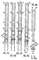
- the casing disposal device comprises a surface installation (not shown) by means of which a train of tubular rods 28 (FIGS. 4A to 4E) carrying at its lower end a tool cutting 30 is introduced into the casing 18.
- the surface installation allows the ascent and descent of the drill string 28, as well as its rotation drive.
- the drill string 28 is formed for this purpose of elementary tubular rods, called “macaroni", which are screwed end to end as the tool is lowered and which are unscrewed during its ascent.
- This surface installation called “repelling” installation (in English, “snubbing") is a known installation which makes it possible at all times to guarantee the seal between the drill string and the interior of the casing into which the latter penetrates.
- This installation includes hydraulic cylinders which, by means of anchoring corners, make it possible to force the drill string to enter the pressurized well at the start of the descent, and to hold it against its weight at the end of the descent. It also allows the rotating drill string to be driven, to fill it with water and to apply pressure pulses to the water column thus formed at will.
- the cutting tool 30 is mounted at the lower end of the drill string 28 by means of disconnection means 32 which will be described in detail below with reference to Figures 7A and 7B.
- the cutting tool 30 comprises a non-rotating lower part 34 in which are housed anchoring means 36 and a rotary upper part 38 in which are housed cutting means 40.
- the lower part 34 is intended to be anchored to the inside the casing 18 using the anchoring means 36, so as to be immobilized in rotation and in translation in the casing.
- the upper part 38 is fixed to the drill string 28 by means of the disconnection means 32, so that it can rotate freely relative to the lower part 34.
- a first operation (not shown in the figures) consists in cutting using any tool (for example explosive) the lower part of the casing 18 comprising the circulation valve 22 and located below the lower end of the casing 14.
- Protective sleeves (not shown) are then installed inside the safety valves 24.
- the cutting tool 30 is then gradually lowered, using the surface installation, after having fixed it to the lower end of the tubular rod train 28 to a level corresponding to the first cut to be made. , at the lower part of the casing 18 (FIG. 4A).
- the anchoring means 36 as well as the cutting means 40 occupy their retracted rest position.
- the drill string 28 is filled with water.
- the anchoring means 36 are actuated by sending a pressure signal through the column of liquid filling the train of rods 28, in a manner which will be described in detail later.
- the lower part 34 of the tool is then secured in rotation and in translation of the casing 18 (FIG. 4B).
- a tensile force for example of 2 tonnes is exerted on the drill string 28, in order to check the good performance of the anchoring means.
- the value of this tensile force is chosen to correspond to the weight that the anchoring means will have to retain after cutting, which avoids any risk of premature release of the section cut at this time.
- the cutting operation can then be started (FIG. 4C), by rotating the upper part 38 of the tool from the surface, through the drill string 28 and disconnection means 32 (arrow F1).
- a downward oriented force (arrow F2) corresponding to about 1 ton of weight on the anchoring means 36
- the knives 42 of the cutting means 40 then move away and attack the casing under the effect of the rotation of the upper part 38 of the tool.
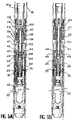
- a lower module for anchoring the cutting tool 30, comprising the anchoring means 36, will now be described in detail with reference to FIGS. 5A and 5B.
- This lower anchoring module comprises a tubular body 41 closed at its lower end and constituting the lower portion of the non-rotating lower part 34. In its central part, the tubular body 41 constitutes the cylinder of an actuating actuator of the anchoring means 36.
- This actuator further comprises a piston 44 which slides in leaktight manner inside the tubular body 41 and delimits in the latter an upper chamber 46 and a chamber lower 48.
- An axial bore 45 passes through the piston 44 into which at least one passage 47 formed in the piston opens and connecting the bore 45 to the upper chamber 46.
- a passage 50 formed in the tubular body 41 permanently ensures communication between the lower chamber 48 and a closed chamber 52 formed in the lower part of the tubular body 41. This chamber 52 is separated from the bore in which the piston 44 is received. by a tight screwed cap 53.
- Chamber 52 is filled with a pressurized gas such as nitrogen through a filling orifice (not shown), before the cutting tool is lowered into the well.
- the pressure of the gas contained in the chamber 52 is determined so as to always be at least 50 bar higher than the hydrostatic pressure of the water column contained in the drill string to which the cutting tool is suspended.
- the gas pressure in the chamber 52 is equal to approximately 220 bars. Consequently, the piston 44 is continuously pushed upwards with a force at least equal to approximately 1 ton.
- the piston 44 is secured, by means of pins 54 passing through a part of reduced outside diameter of the tubular body 41 above the chamber 46, of an annular part 56 capable of sliding axially on this part reduced outer diameter.
- Annular part 56 has a frustoconical ramp 58 at its upper end.
- the tapered ramp 58 for example forms with the axis of the tool an angle of about 15 °.
- Anchor pieces 60 are regularly distributed around the part of reduced outer diameter of the tubular body 41 above the piece 56. Each of these anchor pieces 60 is supported on the tapered ramp 58 by an additional ramp 62 and can move radially on the tubular body 41 between a retracted position illustrated in FIG. 5A and an anchoring position illustrated in FIG. 5B, against leaf springs 64 fixed on the tubular body 41.
- the outer surface of the anchoring parts 60 is cylindrical and irregular, so as to avoid any risk of relative sliding between these anchoring parts and the casing 18 when the parts are in abutment against the internal surface of the casing .
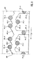
- the piston 44 In its part located below the lower chamber 48 of the jack, the piston 44 supports a rotary barrel 66 which has on its outer surface a groove 68 into which penetrate two diametrically opposed pins 70 fixed radially in the tubular part 41.
- the groove 68 formed on the external surface of the rotary barrel 66 has in developed form such that at each relative axial displacement between the piston 44 and the tubular body forming the lower part 34, the barrel 66 performs a rotation in a determined direction shown diagrammatically by the arrow F in FIG. 8, as a result of the cooperation of the pins 70 with this groove 68.
- the groove 68 is made so that the anchoring means can be passed from their retracted position illustrated in FIG. 5A to their anchoring position illustrated in the FIG. 5B and vice versa, each time a pressure pulse is sent into the drill string 28, each of these positions being maintained by the cooperation of the pins 70 with the groove 68 when this pulse ceases.
- the retracted position illustrated in FIG. 5A corresponds to the support of the pins 70 on a part of the groove 68 closed downwards, in the manner illustrated at 70-1 in FIG. 8.
- the cooperation of the barrel rotary 66 with the pins 70 allows, by sending pressure pulses in the water column which fills the train of rods 28, to alternately pass the anchor pieces 60 from their retracted position to their anchor position, and Conversely.
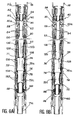
- FIGS. 6A and 6B of the upper cutting module of the tool, in which the cutting means 40 are housed.
- the upper cutting module comprises an outer tubular body 71 provided at its lower end with a thread 71a normally screwed into a thread 41a formed at the upper end of the tubular body 41 (FIG. 5A).
- the tubular bodies 41 and 71 form, when assembled, the non-rotating lower part 34 of the cutting tool.
- An inner tubular body 72 forming the rotary upper part 38 of the tool, is mounted in the outer tubular body 71 so as to be able to rotate freely inside the latter and to be able to move along the axis of the tool with reduced stroke.
- This stroke is limited upwards by the coming into abutment of a central part 72a of relatively large diameter of the internal tubular body 72 against an upper shoulder 74 formed in the external tubular body 71.
- the central part 72a can also come to bear, by means of a ball bearing 76 mounted on its lower face, against a lower shoulder 78 formed in the outer tubular body 71 and limiting the downward movement of the inner tubular body 72.
- a prestressed compression spring 80 is mounted in an annular space formed between the upper part of the outer tubular body 71 and an upper part 72b of relatively small diameter of the inner tubular body 72.
- This compression spring 80 is supported by its lower end on a shoulder of the outer tubular body 71, by means of a ball stop 82.
- the upper end of the spring 80 is in direct contact against the underside of three parts 84 slidably mounted in axial grooves 85 formed in the upper part 72b of the inner tubular body 72 and regularly distributed.
- a heel formed at the lower end of each piece 84 is normally in abutment against a shoulder 86, turned downwards, formed inside the outer tubular body 71.
- the upper end of each of the parts 84 projects beyond the upper end edge of the tubular body 71.
- each piece 84 has an inclined ramp 88 on which the heel of a knife 90 is normally supported, housed in the same axial groove 85 as this piece 84 and pivotally mounted on the upper part of the tubular inner body 72, at above workpiece 84.
- the knives 90 which are advantageously Bowen Tools, Inc. knives, are pivotally mounted on the body 72 by their upper end, by means of an axis 92 orthogonal to the axis of the tool. .
- the heel formed at the lower end of each of the knives 90 is kept permanently in abutment against the corresponding ramp 88 by a leaf spring 94 fixed on the inner tubular body 72.
- the lower end of each knife 90 also has an edge sharp 90a facing outward.
- the arrangement which has just been described allows the knives 90 to normally occupy a retracted position, illustrated in FIG. 6A, under the action of leaf springs 94, when the internal tubular body 72 occupies its high position at inside of the outer tubular body 71.
- FIG. 6B when the inner tubular body 72 occupies its low position inside the outer tubular body 71, the cooperation between the heels of the knives 90 and the ramps 88 has the effect of spreading the knives 90 against the leaf springs 94, in a cutting position in which the cutting edges of the knives 90 are applied against the inner surface of the casing 18 with a cutting force determined by the preload stored in the spring 80.
- This preload can in particular be around 600 daN and remains independent of the force applied by elsewhere on the inner tubular body 72.
- the internal tubular body 72 comprises a lower part 72c of relatively small diameter, terminated by a thread 96, the threads of which comprise an inclined upper face and a straight lower face.
- this thread 96 is screwed into a segmented nut 98 consisting, for example, of four segments resiliently biased inwards by elastic rings 100.
- This segmented nut 98 is immobilized in translation inside the external tubular body 71 and comprises threads complementary to the threads forming the thread 96.
- the system thus formed constitutes a unidirectional thread which prevents any downward movement of the inner tubular body 72 inside the outer tubular body 71 when no rotation of the inner tubular body in the direction of screwing occurs.
- this unidirectional thread allows the inner tubular body 72 to return to its high position under the effect of a simple axial force oriented upwards, without it being necessary to rotate this inner tubular body in the opposite direction.
- the tubing is cut by rotating the tubular body interior 72 by means of the surface installation connected to this body by the drill string 28.
- This rotation has the effect of screwing the thread 96 into the segmented nut 98 and, consequently, of lowering the interior tubular body 72 in the outer tubular body 71.
- the knives 90 pushed by the ramps 88, move apart and come into contact with the casing 18 to be cut.
- the rotational movement transmitted to the inner tubular body 72 is accompanied by the progressive application of a force corresponding to a weight of approximately 1 to 1.5 tonnes.
- the cutting tool is further designed so as to be independent of the pressure fluctuations inherent in the operating conditions. To this end, arrangements are made so that all the sections to which the pressure of the gas contained in the casing as well as the pressure of the water column contained in the drill string apply are equal and in equilibrium.
- three series of rotary joints respectively designated by the references 128, 130 and 132 are placed between the inner tubular body 72 and the outer tubular body 71 (FIGS. 6A and 6B).
- the rotary joints 130 are placed between the outer tubular body 71 and the central part 72a of relatively large diameter of the inner tubular body 72 and the rotary joints 128 and 132 are placed respectively between the upper 72b and lower 72c parts of the inner tubular body 72 and the outer tubular body 71, near the central part 72a.
- the sections of parts 72b and 72c on which are placed the rotary joints 128 and 132 are equal to each other, as well as to the difference in section between the central part 72a and these parts 72b and 72c.
- the outer tubular body has at least one perforation 134 opening out between the rotary joints 130 and 132 and at least one perforation 136 opening out above the rotary joints 128, in the annular chamber containing the spring 80.
- the body inner tubular 72 has at least one perforation 138 opening out between the rotary joints 128 and 130.
- the gas contained in the casing 18 acts on opposite and equal surfaces of the internal tubular body 72 formed by the upper part 72b situated above the O-rings 128 and by the annular lower surface of the central part 72a.
- the pressure of the water column inside the drill string 28 acts simultaneously on the opposite and equal surfaces formed by the upper annular surface of the central part 72a and by the part of this tubular body located in below the O-rings 132.
- the cutting tool illustrated in the figures further comprises a means for controlling the release of the anchoring means 36, in the case where the system previously described with reference to Figures 5A and 5B would not work.
- This emergency release means comprises a sliding tubular rod 102 received in the piston 44 along the axis of the tool and the upper part of which protrudes beyond the upper edge of the piston 44
- This tubular rod 102 is normally immobilized inside the piston 44 by a frangible pin 103, in a position in which a lower part 108 of this rod seals the bore 45 formed in the piston 44, between the passage 47 opening into the upper chamber 46 and a passage 49 opening into the lower chamber 48.
- another part 104 of the tubular rod 102 seals the bore 45 below the passage 49.
- the loosening of the anchoring means 36 can be obtained by descending inside the drill string a tool such as a load bar suspended from a cable.
- This tool strikes the upper end of the tubular rod 102, which has the effect of breaking the frangible pin 103 and causing the rod to descend inside the piston 44.
- the part 108 of the rod 102 then descends below passage 49, which has the effect of communicating the chambers 46 and 48 and equalizing the pressures acting on the piston 44.
- the rod forces the piston 44 to descend thereby driving the part 56, which has the effect of bringing the anchor blocks 60 in their retracted position illustrated in FIG. 5A.
- the entire tool can then be brought back to the surface to be checked and reset.
- the cutting tool according to the invention is advantageously fixed to the lower end of the drill string by means of disconnection means 32 which make it possible to separate the tool from the train of rods in the event that none of the systems described above would allow the anchoring means to be released.
- These disconnection means 32 comprise a female tubular body 110, the lower end of which comprises a thread 110a designed to be screwed into a thread 71b formed at the upper end of the internal tubular body 72 illustrated in FIGS. 6A and 6B.
- the female tubular body 110 is coupled to a male tubular body 112 comprising at its upper end a thread 112a in which is screwed the lower end of the adjacent elementary rod of the drill string 28.
- the female tubular body 110 In its upper part of lesser thickness, the female tubular body 110 has an internal toothing 114. Furthermore, the male tubular body 112 has a lower part of smaller diameter which is received in a sealed manner in the upper part of lesser thickness of the body. tubular 110 and ends with flexible and elastic branches 116 the lower ends of which are provided on their outer surface with teeth 118 complementary to teeth 114.
- the teeth 114 and 118 are normally held in engagement by a sliding sleeve 120 mounted in the tubular body male 112. More specifically, the sleeve 120 comprises in a perforated central part a peripheral rib 122 normally housed in an annular groove 124 formed inside the tubular body 112. Under these conditions, the rigid lower end of the locking ring 120 maintains the lower ends of the flexible arms 116 comprising the teeth 118 engaging the teeth 114.
- a sliding tool 126 shown in broken lines in FIG. 7A is lowered using a cable.
- This tool 126 comes to bear against a shoulder 125 formed in the lower part of the sliding sleeve 120 and allows, by beating, to bring out the circumferential rib 122 from the annular groove 124 by deforming the perforated central part of the sleeve 120.
- the latter then descends inside the male tubular body 112, as illustrated in FIG. 78, so that the lower ends of the flexible branches 116 on which the teeth 118 are formed are opposite a part of smaller diameter of the sleeve 120 and can therefore emerge from the teeth 114 formed inside the female tubular part 110. Disconnection is then obtained and the drill string carrying the tubular body 112 can be reassembled, while the tubular body 110 linked to the the cutting tool remains at the bottom of the well.
- disconnection means which have just been described make it possible, if necessary, to reconnect the drill string to the cutting tool if the disconnection is made before the cutting is carried out. On the contrary, if the disconnection occurs after the cutting of a section by the tool, the whole of the cutting tool is automatically dropped into the cavity and lost.
- disconnection module 32 can in certain cases be eliminated and the control of the anchoring parts and of the knives can be different from that which has been described.
Landscapes
- Life Sciences & Earth Sciences (AREA)
- Geology (AREA)
- Engineering & Computer Science (AREA)
- Mining & Mineral Resources (AREA)
- Environmental & Geological Engineering (AREA)
- General Life Sciences & Earth Sciences (AREA)
- Physics & Mathematics (AREA)
- Fluid Mechanics (AREA)
- Geochemistry & Mineralogy (AREA)
- Marine Sciences & Fisheries (AREA)
- Earth Drilling (AREA)
- Processing Of Stones Or Stones Resemblance Materials (AREA)
- Excavating Of Shafts Or Tunnels (AREA)
Claims (10)
- Verfahren zum Entfernen eines Rohres (18), das koaxial im Innern einer Auskleidung (14) in einem Zugangsbohrloch (10) zu einer Gasspeichersalzkaverne (21) angeordnet ist, dadurch gekennzeichnet, daß es darin besteht, das Rohr (18) in Abschnitte (18a) zu zerschneiden, indem man von unten beginnt, unter Ausführung der folgenden Arbeitsgänge:a) Herablassen eines Trennwerkzeugs (30) in dem Rohr;b) Verankern dieses Werkzeugs in dem Rohr unterhalb eines gewählten Trenniveaus;c) mechanisches Zertrennen des Rohres mittels des Trennwerkzeuges zum Ablängen eines unteren Abschnitts in dem Rohr;d) Herablassen des Werkzeugs, das diesen unteren Abschnitt trägt, bis unter das untere Ende der Auskleidung;e) Lösen des unteren Abschnitts von dem Trennwerkzeug;f) Wiederhochziehen des Trennwerkzeugs in dem Rohr bis zu einem oberhalb des vorhergehenden liegenden Trenniveau;g) Wiederholen der Arbeitsgänge b) bis f) bis zum vollständigen Zerlegen des Rohres.
- Vorrichtung zum Entfernen eines Rohres (18), das koaxial im Innern einer Auskleidung (14) in einem Zugangsbohrloch (10) zu einer Gasspeichersalzkaverne (21) angeordnet ist, dadurch gekennzeichnet, daß sie ein Trennwerkzeug (30) umfaßt, das in das Rohr am Ende eines Zuges von rohrförmigen Stangen (28) herablaßbar ist, welches Trennwerkzeug umfaßt:- Mittel zum Verankern (36) einer nicht umlaufenden unteren Partie (34) des Werkzeugs in dem Rohr, betätigt durch Veränderungen des Drucks im Innern des Stangenzuges entgegen einer Kraft, die von Rückstellmitteln (52) ausgeübt wird; und- Trennmittel (40), umfassend mindestens ein Messer (90), das auf einer oberen umlaufenden Partie (38) des Werkzeugs angeordnet ist, wobei ein Auslenken des Messers sichergestellt wird durch eine Verlagerung nach unten der genannten oberen Partie, relativ zur unteren Partie.
- Vorrichtung nach Anspruch 2, dadurch gekennzeichnet, daß die Verankerungsmittel einen Kolben (44) umfassen, der beweglich längs einer Achse des Werkzeugs in der unteren Partie ist, wobei eine Oberseite des Kolbens dem Druck ausgesetzt ist, der im Inneren des Stangenzuges herrscht, und eine Unterseite des Kolbens der Wirkung der Rückstellmittel (52) unterworfen ist, wobei der Kolben verbunden ist mit mindestens einem Ringteil (56), das mit mindestens einem Verankerungsteil (60) zusammenwirkt zum Verlagern des letzteren radial nach außen, entgegen elastischen Mitteln (64), wenn der Kolben sich nach oben bewegt.
- Vorrichtung nach Anspruch 3, dadurch gekennzeichnet, daß die Rückstellmittel eine geschlossene Kammer (52) umfassen, ausgebildet in der unteren Partie, und mit einem Gasunterdruck gefüllt.
- Vorrichtung nach Anspruch 4, dadurch gekennzeichnet, daß das Trennwerkzeug eine Gleitstange (102) umfaßt, die in dem Kolben montiert ist derart, daß sie eine obere Position einnehmen kann, in der diese Stange eine in dem Kolben ausgebildete Passage (45) sperrt, und ausgebildet zum Inkommunikationbringen der Unterseite und der Oberseite dieses letzteren, und eine untere Position einnehmen kann, in der die Passage offen ist, wobei der Gleitschieber normalerweise in der oberen Position durch ein brechbares Organ (103) gehalten wird.
- Vorrichtung nach einem der Ansprüche 3 bis 5, dadurch gekennzeichnet, daß der Kolben (44) eine drehbare Trommel (66) abstützt, die mit einer Nut (68) versehen ist, in die mindestens ein Stift (70) ragt, welcher von der unteren Partie getragen ist, welche Nut derart ausgebildet ist, daß nach einem Druckimpuls im Inneren des Stangenzuges das Verankerungsteil (56) in ausgefahrener Position gehalten wird, bis ein neuer Druckimpuls in den Stangenzug eingespeist wird.
- Vorrichtung nach einem der Ansprüche 2 bis 6, dadurch gekennzeichnet, daß die obere drehbare Partie des Werkzeugs normalerweise im Eingriff steht mit der unteren, nicht drehbaren Partie über ein Einrichtungsgewinde (96, 98), das eine Verlagerung nach unten der oberen Partie unter der Wirkung einer Drehung dieser letzteren ermöglicht, bis zu einer unteren Trennposition, in der das Gewinde nicht mehr im Eingriff ist, sowie eine Verlagerung nach oben der oberen Partie durch eine einfache Translation dieser letzteren.
- Vorrichtung nach Anspruch 7, dadurch gekennzeichnet, daß das Messer (90) in Anlage an einer Rampe (88) ist, gebildet auf einem Bauteil (84), das gleitbeweglich längs der Werkzeugachse montiert ist, und dessen entgegengesetztes Ende sich auf dem unteren, nicht drehbaren Teil abstützt über ein elastisches vorgespanntes Mittel (80).
- Vorrichtung nach einem der Ansprüche 2 bis 8, dadurch gekennzeichnet, daß das Trennwerkzeug (30) an dem rohrförmigen Stangenzug (28) mittels fernsteuerbarer Lösemittel (32) aufgehangen ist.
- Vorrichtung nach Anspruch 9, dadurch gekennzeichnet, daß die Lösemittel (32) einen rohrförmigen Steckkorpus (112) umfassen, befestigt am unteren Ende des rohrförmigen Stangenzuges, und weiche Arme (116) umfassen, die außen mit Formteilen (118) versehen sind, komplementär zu Formteilen (114), ausgebildet in einem rohrförmigen Einsteckteil (110), das am oberen Ende des Trennwerkzeugs befestigt ist, wobei eine Gleithülse (120) normalerweise in oberer Position in dem rohrförmigen Steckteil immobilisiert ist durch Blockiermittel (122, 124), wodurch die Formteile auf den weichen Armen im Eingriff mit den Formteilen gehalten werden, die in dem rohrförmigen Einsteckteil ausgebildet sind, wobei eine Entriegelung der Blockiermittel, gesteuert durch das Einwirken einer Kraft nach unten auf die Gleithülse (120), diese letztere in eine untere Position versetzt, in der die weichen Arme (116) sich radial nach innen deformieren können zum Freigeben der Formteile, die auf diesen Armen ausgebildet sind, von den Formteilen auf dem rohrförmigen Einsteckteil.
Applications Claiming Priority (2)
| Application Number | Priority Date | Filing Date | Title |
|---|---|---|---|
| FR9004386A FR2660728B1 (fr) | 1990-04-05 | 1990-04-05 | Procede et dispositif d'elimination d'un tubage dispose dans un puits d'acces a une cavite saline de stockage de gaz. |
| FR9004386 | 1990-04-05 |
Publications (2)
| Publication Number | Publication Date |
|---|---|
| EP0451058A1 EP0451058A1 (de) | 1991-10-09 |
| EP0451058B1 true EP0451058B1 (de) | 1994-06-22 |
Family
ID=9395479
Family Applications (1)
| Application Number | Title | Priority Date | Filing Date |
|---|---|---|---|
| EP19910400921 Expired - Lifetime EP0451058B1 (de) | 1990-04-05 | 1991-04-05 | Verfahren und Vorrichtung zum Ablegen eines Steigrohres in einem Zugangsbohrloch einer Salzkaverne für Gasspeicherung |
Country Status (3)
| Country | Link |
|---|---|
| EP (1) | EP0451058B1 (de) |
| DE (1) | DE69102571T2 (de) |
| FR (1) | FR2660728B1 (de) |
Families Citing this family (2)
| Publication number | Priority date | Publication date | Assignee | Title |
|---|---|---|---|---|
| US5732770A (en) * | 1996-08-02 | 1998-03-31 | Weatherford/Lamb, Inc. | Wellbore cutter |
| NO332901B1 (no) * | 2009-11-10 | 2013-01-28 | Norse Cutting & Abandonment As | Fremgangsmate og anordning for a stenge en bronn i grunnen |
Family Cites Families (6)
| Publication number | Priority date | Publication date | Assignee | Title |
|---|---|---|---|---|
| US2481637A (en) * | 1945-02-23 | 1949-09-13 | A 1 Bit & Tool Company | Combined milling tool and pipe puller |
| US3045752A (en) * | 1958-03-25 | 1962-07-24 | Baker Oil Tools Inc | Milling apparatus for removing objects from well bores |
| US3019840A (en) * | 1958-06-25 | 1962-02-06 | Thomas A Kennard | Retrieving tool |
| US3277654A (en) * | 1963-04-15 | 1966-10-11 | Phillips Petroleum Co | Underground storage caverns and method of making the same and of storing fluids therein |
| US4047568A (en) * | 1976-04-26 | 1977-09-13 | International Enterprises, Inc. | Method and apparatus for cutting and retrieving casing from a well bore |
| US4550781A (en) * | 1984-06-06 | 1985-11-05 | A-Z International Tool Company | Method of and apparatus for cutting and recovering of submarine surface casing |
-
1990
- 1990-04-05 FR FR9004386A patent/FR2660728B1/fr not_active Expired - Lifetime
-
1991
- 1991-04-05 EP EP19910400921 patent/EP0451058B1/de not_active Expired - Lifetime
- 1991-04-05 DE DE1991602571 patent/DE69102571T2/de not_active Expired - Fee Related
Also Published As
| Publication number | Publication date |
|---|---|
| DE69102571T2 (de) | 1995-02-09 |
| FR2660728A1 (fr) | 1991-10-11 |
| EP0451058A1 (de) | 1991-10-09 |
| FR2660728B1 (fr) | 1992-07-31 |
| DE69102571D1 (de) | 1994-07-28 |
Similar Documents
| Publication | Publication Date | Title |
|---|---|---|
| EP1525371B1 (de) | Teleskopführungsleitung für offshore-bohren | |
| EP0265344B1 (de) | Verfahren zum Herstellen eines Pfahls im Boden, sowie Bohrmaschine und Vorrichtung zur Ausführung dieses Verfahrens | |
| FR2958966A1 (fr) | Procede et dispositif d'obturation d'un puits au moyen d'un bouchon expansible, bouchon pour la mise en oeuvre du procede, et outil extracteur adapte pour le retirer | |
| FR2519688A1 (fr) | Systeme d'etancheite pour puits de forage dans lequel circule un fluide chaud | |
| WO1991000410A1 (fr) | Dispositif pour guider un outil de forage dans un puits et exercer sur lui une force hydraulique | |
| FR2607865A1 (fr) | Procede et appareil de perforation de tubage pour puits de petrole | |
| EP2417323B1 (de) | Verschlussvorrichtung für ein bohrgerät | |
| FR2495704A1 (fr) | Mecanisme hydraulique a double effet | |
| EP0689637A1 (de) | Verfahren und vorrichtung zur zementierung eines bohrloches | |
| FR2630158A1 (fr) | Procedes et appareils de completion d'un puits de forage de configuration deviee, et de mise en place d'un filtre a gravier dans un tel puits | |
| FR2814494A1 (fr) | Moteur de trepan de carottage ameliore et procede pour obtenir un echantillon de carotte de materiau | |
| CA1273286A (fr) | Dispositif pour mettre en place un outil ou instrument dans une conduite utilisable notamment pour l'exploitation en fond de puits de pompes hydrauliques autonomes, en production par l'interieur d'un tubing | |
| EP0321610B1 (de) | Erdölbohrungssicherheitsventil und Werkzeuge zum Setzen und Zurückziehen eines derartigen Ventils | |
| EP1259792B1 (de) | Verfahren und vorrichtung zur einbringung eines rohrförmigem werkzeuges in den seeboden zwecks probenentnahme oder messung der eigenschaften dieses bodens, insbesondere in grosser tiefe | |
| EP2125503A1 (de) | Vorrichtung zum schneiden und öffnen/schliessen eines loches in eine wand auf dem meeresgrund | |
| EP0451058B1 (de) | Verfahren und Vorrichtung zum Ablegen eines Steigrohres in einem Zugangsbohrloch einer Salzkaverne für Gasspeicherung | |
| EP0382607A1 (de) | Vorrichtung zum Herstellen von Pfählen im Boden mit einem kontinuierlichen hohlen Bohrer | |
| EP0165154B1 (de) | Verfahren und Vorrichtung, um mit Hilfe von Spezialwerkzeugen Operationen wie Messungen in stark gegen die Vertikale geneigten oder horizontalen Bohrlochteilen vorzunehmen | |
| EP0531336A1 (de) | Doppelkernrohr für abgelenkte bohrungen. | |
| FR2772826A1 (fr) | Procede et outil pour traiter au moins la paroi d'une zone critique d'un trou de forage | |
| EP3414399B1 (de) | Verfahren zur herstellung einer verankerungszugstange und verankerungszugstange | |
| EP0677437A1 (de) | Verfahren und Vorrichtung gegen die Längsbewegung von Wasserfahrzeugen | |
| EP4028626A1 (de) | Verfahren und vorrichtung für bohrloch mit grossem durchmesser oder graben von bohrungen nach mehreren neigungen | |
| FR2832454A1 (fr) | Equipement de forage de puits verticaux | |
| EP2697470A1 (de) | Verfahren und vorrichtung für zerstörungsfreies bohren |
Legal Events
| Date | Code | Title | Description |
|---|---|---|---|
| PUAI | Public reference made under article 153(3) epc to a published international application that has entered the european phase |
Free format text: ORIGINAL CODE: 0009012 |
|
| AK | Designated contracting states |
Kind code of ref document: A1 Designated state(s): DE GB IT NL |
|
| 17P | Request for examination filed |
Effective date: 19920404 |
|
| 17Q | First examination report despatched |
Effective date: 19930719 |
|
| GRAA | (expected) grant |
Free format text: ORIGINAL CODE: 0009210 |
|
| AK | Designated contracting states |
Kind code of ref document: B1 Designated state(s): DE GB IT NL |
|
| REF | Corresponds to: |
Ref document number: 69102571 Country of ref document: DE Date of ref document: 19940728 |
|
| ITF | It: translation for a ep patent filed | ||
| GBT | Gb: translation of ep patent filed (gb section 77(6)(a)/1977) |
Effective date: 19940906 |
|
| PLBE | No opposition filed within time limit |
Free format text: ORIGINAL CODE: 0009261 |
|
| STAA | Information on the status of an ep patent application or granted ep patent |
Free format text: STATUS: NO OPPOSITION FILED WITHIN TIME LIMIT |
|
| 26N | No opposition filed | ||
| PGFP | Annual fee paid to national office [announced via postgrant information from national office to epo] |
Ref country code: DE Payment date: 19960603 Year of fee payment: 6 |
|
| PG25 | Lapsed in a contracting state [announced via postgrant information from national office to epo] |
Ref country code: DE Free format text: LAPSE BECAUSE OF NON-PAYMENT OF DUE FEES Effective date: 19980101 |
|
| REG | Reference to a national code |
Ref country code: GB Ref legal event code: IF02 |
|
| PG25 | Lapsed in a contracting state [announced via postgrant information from national office to epo] |
Ref country code: IT Free format text: LAPSE BECAUSE OF NON-PAYMENT OF DUE FEES;WARNING: LAPSES OF ITALIAN PATENTS WITH EFFECTIVE DATE BEFORE 2007 MAY HAVE OCCURRED AT ANY TIME BEFORE 2007. THE CORRECT EFFECTIVE DATE MAY BE DIFFERENT FROM THE ONE RECORDED. Effective date: 20050405 |
|
| PGFP | Annual fee paid to national office [announced via postgrant information from national office to epo] |
Ref country code: GB Payment date: 20100325 Year of fee payment: 20 |
|
| PGFP | Annual fee paid to national office [announced via postgrant information from national office to epo] |
Ref country code: NL Payment date: 20100402 Year of fee payment: 20 |
|
| REG | Reference to a national code |
Ref country code: NL Ref legal event code: V4 Effective date: 20110405 |
|
| REG | Reference to a national code |
Ref country code: GB Ref legal event code: PE20 Expiry date: 20110404 |
|
| PG25 | Lapsed in a contracting state [announced via postgrant information from national office to epo] |
Ref country code: NL Free format text: LAPSE BECAUSE OF EXPIRATION OF PROTECTION Effective date: 20110405 Ref country code: GB Free format text: LAPSE BECAUSE OF EXPIRATION OF PROTECTION Effective date: 20110404 |