EP0451110A2 - Dispositif pour déconnecter en cas de court-circuit des charges alimentées par une alimentation de secours - Google Patents
Dispositif pour déconnecter en cas de court-circuit des charges alimentées par une alimentation de secours Download PDFInfo
- Publication number
- EP0451110A2 EP0451110A2 EP91810237A EP91810237A EP0451110A2 EP 0451110 A2 EP0451110 A2 EP 0451110A2 EP 91810237 A EP91810237 A EP 91810237A EP 91810237 A EP91810237 A EP 91810237A EP 0451110 A2 EP0451110 A2 EP 0451110A2
- Authority
- EP
- European Patent Office
- Prior art keywords
- consumer
- circuit
- current
- transformer
- power supply
- Prior art date
- Legal status (The legal status is an assumption and is not a legal conclusion. Google has not performed a legal analysis and makes no representation as to the accuracy of the status listed.)
- Granted
Links
Images

Classifications
-
- H—ELECTRICITY
- H02—GENERATION; CONVERSION OR DISTRIBUTION OF ELECTRIC POWER
- H02J—ELECTRIC POWER NETWORKS; CIRCUIT ARRANGEMENTS OR SYSTEMS FOR SUPPLYING OR DISTRIBUTING ELECTRIC POWER; SYSTEMS FOR STORING ELECTRIC ENERGY
- H02J9/00—Circuit arrangements for emergency or stand-by power supply, e.g. for emergency lighting
- H02J9/04—Circuit arrangements for emergency or stand-by power supply, e.g. for emergency lighting in which the distribution system is disconnected from the normal source and connected to a standby source
- H02J9/06—Circuit arrangements for emergency or stand-by power supply, e.g. for emergency lighting in which the distribution system is disconnected from the normal source and connected to a standby source with automatic change-over, e.g. UPS systems
- H02J9/062—Circuit arrangements for emergency or stand-by power supply, e.g. for emergency lighting in which the distribution system is disconnected from the normal source and connected to a standby source with automatic change-over, e.g. UPS systems for AC powered loads
-
- H—ELECTRICITY
- H02—GENERATION; CONVERSION OR DISTRIBUTION OF ELECTRIC POWER
- H02H—EMERGENCY PROTECTIVE CIRCUIT ARRANGEMENTS
- H02H3/00—Emergency protective circuit arrangements for automatic disconnection directly responsive to an undesired change from normal electric working condition with or without subsequent reconnection ; integrated protection
- H02H3/08—Emergency protective circuit arrangements for automatic disconnection directly responsive to an undesired change from normal electric working condition with or without subsequent reconnection ; integrated protection responsive to excess current
Definitions
- the invention relates to a device for switching off electrical consumers in emergency power mode when a short circuit occurs.
- An uninterruptible power supply is required for special electrical consumers. Such consumers could be: lighting systems for comfort and security in commercial buildings, banks, public buildings, hotels, hospitals, old people's homes and nursing homes, underground garages, shopping centers etc., and delivery or metering pumps in devices for life-supporting measures in the medical field.
- special precautions are taken for the most uninterruptible power supply possible in the event of a failure of the public power grid or in the event of a consumer failure due to a short circuit.
- the known systems are equipped with at least one emergency power unit, which can consist, for example, of a drive motor with a generator or batteries charged by rectifiers with an inverter for supplying the consumers, for example via an emergency power supply.
- the known emergency power units work well, but have the disadvantage that in the event of a short circuit, which occurs during the emergency power supply occurs in one of the consumers, the supply for all consumers can fail due to overload, so that the emergency power operation breaks down altogether, which can cause serious problems in the security area and in life-support measures.
- the object of the invention is to eliminate this disadvantage and to provide increased operational safety, particularly in the case of lighting systems and devices in the medical field.
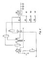
- FIG. 1 shows the electrical circuit of a system with a large number of consumers which are connected to form groups.
- the system has a power supply 1, usually from the public network, and an emergency power unit, which consists of a rectifier 2, several batteries 3 and an inverter 4. These batteries are charged during normal power supply and kept in the charged state.
- the inverter 4 takes over the power supply without interruption in the event of a voltage drop or in the event of a failure of the public grid 1.
- FIG. 1 shows this state of the emergency power supply for the consumer groups 8, 9, 10, 11 by the inverter 4 via the transformer 5 and contacts 61 and 71 electromagnetic relays 6 and 7.
- At the input of each consumer group are a fuse 81, 91, 101, 111 and Monitoring logic 82, 92, 102, 112 provided.
- the monitoring logic gives a control signal to the controller 13 when a voltage drop or a failure of the public network occurs, which causes the relay 7 to be energized, so that the working switch 71 is moved into the position shown.
- the consumer groups 8, 9, 10, 11 are connected to the emergency power supply of the inverter 4 via the normally closed contact 61 (drawn position) of the non-excited relay 6 and via the transformer 5.
- the current monitor 12 which is in the primary circuit, detects the increased current and excites the relay 6, which brings its normally closed contact 61 into the other position (not shown), so that a center tap 53 of the transformer is switched on, as a result of which the secondary voltage is reduced.
- the secondary current increases 10 to 100 times and only via the fuse in the position switch 71 in the position shown (relay 7 is still energized) flows with a short-circuited consumer group.
- This fuse or isolating device responds through this greatly increased current and switches off the relevant consumer group from the emergency power supply. In this way, the emergency power supply for the other consumer groups is maintained.
- FIG. 2 shows an alternative which is used to generate an increased current for switching off the consumer group in which a short circuit has occurred during emergency operation.
- the circuit of each monitoring logic 82, 92, 102, 112 and the normally closed contact 71 controlled by the relay 7 are in the position shown.
- a current monitor 12 and an overcurrent generator 14 are arranged in the primary circuit 51 of the transformer 5, the output of which is connected to the isolating elements or fuses 81, 91, 101, 111 of the consumer groups 8, 9, 100, 110.
- the consumer groups are supplied by the emergency power unit 2, 3, 4. If a short circuit occurs in any consumer (e.g.
- the current in the secondary circuit 52 of the transformer 5 increases, which produces a voltage increase in the primary circuit 51.
- the current monitor 12 responds to this voltage increase and outputs a current 10 to 100 times higher to the fuses 81, 91, 101, 111, which disconnects the fuse that belongs to the consumer group 8 with the short circuit, so that this consumer group is switched off and the inverter 4 can continue to supply the other consumer groups with electricity.
- relays 6 and 7 in FIGS. 1 and 2 are electronic Switches such as thyristors can be replaced.
- Such thyrister circuits are known.
- the transformer 5 can be used, which is already available for charging the batteries 3 by the rectifier, since this is only used during the normal power supply by the public network.
- FIGS. 1 and 2 only require simple components, which results in low manufacturing costs.
Landscapes
- Business, Economics & Management (AREA)
- Emergency Management (AREA)
- Engineering & Computer Science (AREA)
- Power Engineering (AREA)
- Stand-By Power Supply Arrangements (AREA)
- Emergency Protection Circuit Devices (AREA)
- Protection Of Static Devices (AREA)
- Direct Current Feeding And Distribution (AREA)
Applications Claiming Priority (2)
| Application Number | Priority Date | Filing Date | Title |
|---|---|---|---|
| CH1157/90A CH680320A5 (fr) | 1990-04-05 | 1990-04-05 | |
| CH1157/90 | 1990-04-05 |
Publications (3)
| Publication Number | Publication Date |
|---|---|
| EP0451110A2 true EP0451110A2 (fr) | 1991-10-09 |
| EP0451110A3 EP0451110A3 (fr) | 1994-03-02 |
| EP0451110B1 EP0451110B1 (fr) | 1995-05-17 |
Family
ID=4203814
Family Applications (1)
| Application Number | Title | Priority Date | Filing Date |
|---|---|---|---|
| EP91810237A Expired - Lifetime EP0451110B1 (fr) | 1990-04-05 | 1991-04-03 | Dispositif pour déconnecter en cas de court-circuit des charges alimentées par une alimentation de secours |
Country Status (5)
| Country | Link |
|---|---|
| EP (1) | EP0451110B1 (fr) |
| AT (1) | ATE122828T1 (fr) |
| CH (1) | CH680320A5 (fr) |
| DE (1) | DE59105487D1 (fr) |
| ES (1) | ES2072589T3 (fr) |
Cited By (2)
| Publication number | Priority date | Publication date | Assignee | Title |
|---|---|---|---|---|
| US8530765B2 (en) | 2010-11-19 | 2013-09-10 | Bae Systems Controls Inc. | Hybrid vehicle high voltage multiple battery disconnect |
| RU2625564C1 (ru) * | 2016-07-07 | 2017-07-17 | Открытое Акционерное Общество "Научно-Исследовательский И Проектно-Конструкторский Институт Информатизации, Автоматизации И Связи На Железнодорожном Транспорте" | Способ отключения источников электроснабжения от нагрузки потребителя и устройство для его осуществления |
Family Cites Families (3)
| Publication number | Priority date | Publication date | Assignee | Title |
|---|---|---|---|---|
| DE3127460C2 (de) * | 1981-07-11 | 1985-09-19 | Industrie Automation Halbleitergerätebau GmbH & Co, 7801 March | Schaltungsanordnung für einen leistungsbegrenzten Wechselrichter |
| JPS61262026A (ja) * | 1985-05-15 | 1986-11-20 | 三菱電機株式会社 | 無停電電源装置の短絡保護方式 |
| DE3519151C1 (de) * | 1985-05-29 | 1987-01-02 | Piller Gmbh Co Kg Anton | Statischer Wechselrichter mit einer Schaltung zur Stromueberhoehung im Kurzschlussfall |
-
1990
- 1990-04-05 CH CH1157/90A patent/CH680320A5/de not_active IP Right Cessation
-
1991
- 1991-04-03 DE DE59105487T patent/DE59105487D1/de not_active Expired - Fee Related
- 1991-04-03 ES ES91810237T patent/ES2072589T3/es not_active Expired - Lifetime
- 1991-04-03 EP EP91810237A patent/EP0451110B1/fr not_active Expired - Lifetime
- 1991-04-03 AT AT91810237T patent/ATE122828T1/de not_active IP Right Cessation
Cited By (2)
| Publication number | Priority date | Publication date | Assignee | Title |
|---|---|---|---|---|
| US8530765B2 (en) | 2010-11-19 | 2013-09-10 | Bae Systems Controls Inc. | Hybrid vehicle high voltage multiple battery disconnect |
| RU2625564C1 (ru) * | 2016-07-07 | 2017-07-17 | Открытое Акционерное Общество "Научно-Исследовательский И Проектно-Конструкторский Институт Информатизации, Автоматизации И Связи На Железнодорожном Транспорте" | Способ отключения источников электроснабжения от нагрузки потребителя и устройство для его осуществления |
Also Published As
| Publication number | Publication date |
|---|---|
| DE59105487D1 (de) | 1995-06-22 |
| CH680320A5 (fr) | 1992-07-31 |
| EP0451110B1 (fr) | 1995-05-17 |
| ES2072589T3 (es) | 1995-07-16 |
| EP0451110A3 (fr) | 1994-03-02 |
| ATE122828T1 (de) | 1995-06-15 |
Similar Documents
| Publication | Publication Date | Title |
|---|---|---|
| DE2657167C3 (de) | Schaltung zum selbsttätigen Umschalten der Stromversorgung einer Last von einer Primärstromquelle auf eine Sekundärstromquelle | |
| WO2021144103A1 (fr) | Dispositif de changement, kit de rattrapage et procédé pour fournir de l'énergie électrique à une charge | |
| EP0451110B1 (fr) | Dispositif pour déconnecter en cas de court-circuit des charges alimentées par une alimentation de secours | |
| DE102020210554A1 (de) | Wechselrichter | |
| DE102022125440A1 (de) | Vorrichtung und Verfahren zur Stromversorgung von Geräten in medizinischen Einrichtungen | |
| DE3738493A1 (de) | Fehlerortungseinrichtung | |
| EP2498300A1 (fr) | Installation photovoltaïque, dispositif de commande et dispositif de commutation | |
| DE2541598A1 (de) | Elektrische stromversorgungsschaltung mit zwei energiequellen | |
| EP2608343B1 (fr) | Alimentation électrique | |
| DE1538448C3 (de) | Verbrauchernetzwerk | |
| DE102017124567B4 (de) | Batteriesystem, lokales Stromnetz und Trennschalter | |
| DE102021109645A1 (de) | Energieversorgungsvorrichtung mit sicherheitsgerichteter Abschaltung sowie Verfahren zum Abschalten einer Energieversorgungsvorrichtung | |
| DE102024113544B4 (de) | Umschaltvorrichtung, Notstromanlage und Verfahren zum Betrieb der Notstromanlage | |
| DE2611674C2 (fr) | ||
| CH658837A5 (en) | Circuit arrangement for driving a current load in a failsafe fashion in terms of signalling technology | |
| AT61448B (de) | Schaltungseinrichtung zur selbsttätigen Abschaltung eines schadhaften Generators in elektrischen Zentralen. | |
| DE3111400C2 (de) | Einrichtung zum Phasen-Differenzschutz von Elektromotoren | |
| DE3613630C2 (fr) | ||
| DE3342113A1 (de) | Transformator als eine pausenlose, kontinuierliche stromquelle mit wechselspannung | |
| DE918582C (de) | Notstromeinrichtung, insbesondere zum Betrieb von Leuchtstoffroehren | |
| DE202023104012U1 (de) | Wechselrichter mit Umschaltvorrichtung zur Steuerungsversorgung | |
| DE932318C (de) | Anordnung zur Betaetigung von Zellenschaltern fuer Akkumulatorenbatterien | |
| DE269160C (fr) | ||
| DE3333820C2 (fr) | ||
| DE2255200C3 (de) | Schaltungsanordnung für relaisüberwachte Stromkreise zum Feststellen von Aderberührungen |
Legal Events
| Date | Code | Title | Description |
|---|---|---|---|
| PUAI | Public reference made under article 153(3) epc to a published international application that has entered the european phase |
Free format text: ORIGINAL CODE: 0009012 |
|
| AK | Designated contracting states |
Kind code of ref document: A2 Designated state(s): AT BE CH DE ES FR GB IT LI LU NL SE |
|
| PUAL | Search report despatched |
Free format text: ORIGINAL CODE: 0009013 |
|
| AK | Designated contracting states |
Kind code of ref document: A3 Designated state(s): AT BE CH DE ES FR GB IT LI LU NL SE |
|
| 17P | Request for examination filed |
Effective date: 19940707 |
|
| 17Q | First examination report despatched |
Effective date: 19941014 |
|
| GRAA | (expected) grant |
Free format text: ORIGINAL CODE: 0009210 |
|
| AK | Designated contracting states |
Kind code of ref document: B1 Designated state(s): AT BE CH DE ES FR GB IT LI LU NL SE |
|
| REF | Corresponds to: |
Ref document number: 122828 Country of ref document: AT Date of ref document: 19950615 Kind code of ref document: T |
|
| REF | Corresponds to: |
Ref document number: 59105487 Country of ref document: DE Date of ref document: 19950622 |
|
| GBT | Gb: translation of ep patent filed (gb section 77(6)(a)/1977) |
Effective date: 19950612 |
|
| REG | Reference to a national code |
Ref country code: ES Ref legal event code: FG2A Ref document number: 2072589 Country of ref document: ES Kind code of ref document: T3 |
|
| ITF | It: translation for a ep patent filed | ||
| ET | Fr: translation filed | ||
| PLBE | No opposition filed within time limit |
Free format text: ORIGINAL CODE: 0009261 |
|
| 26N | No opposition filed | ||
| REG | Reference to a national code |
Ref country code: GB Ref legal event code: IF02 |
|
| PGFP | Annual fee paid to national office [announced via postgrant information from national office to epo] |
Ref country code: SE Payment date: 20070319 Year of fee payment: 17 |
|
| PGFP | Annual fee paid to national office [announced via postgrant information from national office to epo] |
Ref country code: DE Payment date: 20070320 Year of fee payment: 17 |
|
| PGFP | Annual fee paid to national office [announced via postgrant information from national office to epo] |
Ref country code: AT Payment date: 20070413 Year of fee payment: 17 |
|
| PGFP | Annual fee paid to national office [announced via postgrant information from national office to epo] |
Ref country code: NL Payment date: 20070417 Year of fee payment: 17 |
|
| PGFP | Annual fee paid to national office [announced via postgrant information from national office to epo] |
Ref country code: ES Payment date: 20070425 Year of fee payment: 17 |
|
| PGFP | Annual fee paid to national office [announced via postgrant information from national office to epo] |
Ref country code: LU Payment date: 20070426 Year of fee payment: 17 |
|
| PGFP | Annual fee paid to national office [announced via postgrant information from national office to epo] |
Ref country code: CH Payment date: 20070719 Year of fee payment: 17 |
|
| PGFP | Annual fee paid to national office [announced via postgrant information from national office to epo] |
Ref country code: BE Payment date: 20070419 Year of fee payment: 17 Ref country code: IT Payment date: 20070607 Year of fee payment: 17 |
|
| PGFP | Annual fee paid to national office [announced via postgrant information from national office to epo] |
Ref country code: FR Payment date: 20070418 Year of fee payment: 17 |
|
| BERE | Be: lapsed |
Owner name: *ALMAT BRUNO KESSLER Effective date: 20080430 |
|
| REG | Reference to a national code |
Ref country code: CH Ref legal event code: PL |
|
| EUG | Se: european patent has lapsed | ||
| PGFP | Annual fee paid to national office [announced via postgrant information from national office to epo] |
Ref country code: GB Payment date: 20080402 Year of fee payment: 18 |
|
| NLV4 | Nl: lapsed or anulled due to non-payment of the annual fee |
Effective date: 20081101 |
|
| PG25 | Lapsed in a contracting state [announced via postgrant information from national office to epo] |
Ref country code: LI Free format text: LAPSE BECAUSE OF NON-PAYMENT OF DUE FEES Effective date: 20080430 Ref country code: NL Free format text: LAPSE BECAUSE OF NON-PAYMENT OF DUE FEES Effective date: 20081101 Ref country code: DE Free format text: LAPSE BECAUSE OF NON-PAYMENT OF DUE FEES Effective date: 20081101 Ref country code: CH Free format text: LAPSE BECAUSE OF NON-PAYMENT OF DUE FEES Effective date: 20080430 |
|
| REG | Reference to a national code |
Ref country code: FR Ref legal event code: ST Effective date: 20081231 |
|
| PG25 | Lapsed in a contracting state [announced via postgrant information from national office to epo] |
Ref country code: AT Free format text: LAPSE BECAUSE OF NON-PAYMENT OF DUE FEES Effective date: 20080403 |
|
| PG25 | Lapsed in a contracting state [announced via postgrant information from national office to epo] |
Ref country code: BE Free format text: LAPSE BECAUSE OF NON-PAYMENT OF DUE FEES Effective date: 20080430 |
|
| PG25 | Lapsed in a contracting state [announced via postgrant information from national office to epo] |
Ref country code: FR Free format text: LAPSE BECAUSE OF NON-PAYMENT OF DUE FEES Effective date: 20080430 |
|
| REG | Reference to a national code |
Ref country code: ES Ref legal event code: FD2A Effective date: 20080404 |
|
| PG25 | Lapsed in a contracting state [announced via postgrant information from national office to epo] |
Ref country code: ES Free format text: LAPSE BECAUSE OF NON-PAYMENT OF DUE FEES Effective date: 20080404 |
|
| PG25 | Lapsed in a contracting state [announced via postgrant information from national office to epo] |
Ref country code: IT Free format text: LAPSE BECAUSE OF NON-PAYMENT OF DUE FEES Effective date: 20080403 |
|
| GBPC | Gb: european patent ceased through non-payment of renewal fee |
Effective date: 20090403 |
|
| PG25 | Lapsed in a contracting state [announced via postgrant information from national office to epo] |
Ref country code: GB Free format text: LAPSE BECAUSE OF NON-PAYMENT OF DUE FEES Effective date: 20090403 |
|
| PG25 | Lapsed in a contracting state [announced via postgrant information from national office to epo] |
Ref country code: LU Free format text: LAPSE BECAUSE OF NON-PAYMENT OF DUE FEES Effective date: 20080403 |
|
| PG25 | Lapsed in a contracting state [announced via postgrant information from national office to epo] |
Ref country code: SE Free format text: LAPSE BECAUSE OF NON-PAYMENT OF DUE FEES Effective date: 20080404 |