EP0451209B1 - Agencement servant a detecter la presence de particules metalliques portees par un fluide - Google Patents
Agencement servant a detecter la presence de particules metalliques portees par un fluide Download PDFInfo
- Publication number
- EP0451209B1 EP0451209B1 EP90901963A EP90901963A EP0451209B1 EP 0451209 B1 EP0451209 B1 EP 0451209B1 EP 90901963 A EP90901963 A EP 90901963A EP 90901963 A EP90901963 A EP 90901963A EP 0451209 B1 EP0451209 B1 EP 0451209B1
- Authority
- EP
- European Patent Office
- Prior art keywords
- passage
- arrangement
- coil
- capacitor
- fluid
- Prior art date
- Legal status (The legal status is an assumption and is not a legal conclusion. Google has not performed a legal analysis and makes no representation as to the accuracy of the status listed.)
- Expired - Lifetime
Links
- 239000012530 fluid Substances 0.000 title claims abstract description 45
- 239000013528 metallic particle Substances 0.000 title claims abstract description 29
- 239000003990 capacitor Substances 0.000 claims abstract description 28
- 239000000523 sample Substances 0.000 claims description 40
- 230000005291 magnetic effect Effects 0.000 claims description 29
- 230000001939 inductive effect Effects 0.000 claims description 19
- 239000004020 conductor Substances 0.000 claims description 8
- 230000001419 dependent effect Effects 0.000 claims description 3
- 230000005284 excitation Effects 0.000 claims 2
- 239000002245 particle Substances 0.000 description 44
- 230000005294 ferromagnetic effect Effects 0.000 description 29
- 238000001514 detection method Methods 0.000 description 28
- 238000013459 approach Methods 0.000 description 14
- 230000004044 response Effects 0.000 description 9
- 238000010276 construction Methods 0.000 description 8
- 238000012544 monitoring process Methods 0.000 description 7
- 230000008859 change Effects 0.000 description 6
- 230000035945 sensitivity Effects 0.000 description 6
- 230000008901 benefit Effects 0.000 description 5
- 238000011161 development Methods 0.000 description 5
- 230000018109 developmental process Effects 0.000 description 5
- 230000036541 health Effects 0.000 description 5
- 239000000314 lubricant Substances 0.000 description 5
- 238000005461 lubrication Methods 0.000 description 5
- 238000004804 winding Methods 0.000 description 5
- 239000010687 lubricating oil Substances 0.000 description 4
- 239000000463 material Substances 0.000 description 4
- 230000000694 effects Effects 0.000 description 3
- 230000005681 electric displacement field Effects 0.000 description 3
- 230000005672 electromagnetic field Effects 0.000 description 3
- 238000007689 inspection Methods 0.000 description 3
- 230000007774 longterm Effects 0.000 description 3
- 239000003921 oil Substances 0.000 description 3
- RYGMFSIKBFXOCR-UHFFFAOYSA-N Copper Chemical compound [Cu] RYGMFSIKBFXOCR-UHFFFAOYSA-N 0.000 description 2
- 230000004323 axial length Effects 0.000 description 2
- 229910052802 copper Inorganic materials 0.000 description 2
- 239000010949 copper Substances 0.000 description 2
- 238000013461 design Methods 0.000 description 2
- 230000009429 distress Effects 0.000 description 2
- 239000000446 fuel Substances 0.000 description 2
- 230000006698 induction Effects 0.000 description 2
- 230000007246 mechanism Effects 0.000 description 2
- 238000000034 method Methods 0.000 description 2
- 230000010363 phase shift Effects 0.000 description 2
- 238000004321 preservation Methods 0.000 description 2
- 238000011179 visual inspection Methods 0.000 description 2
- 230000006978 adaptation Effects 0.000 description 1
- 230000002411 adverse Effects 0.000 description 1
- 230000032683 aging Effects 0.000 description 1
- 230000015556 catabolic process Effects 0.000 description 1
- 230000002596 correlated effect Effects 0.000 description 1
- 230000000875 corresponding effect Effects 0.000 description 1
- 238000006731 degradation reaction Methods 0.000 description 1
- 239000003989 dielectric material Substances 0.000 description 1
- 230000005684 electric field Effects 0.000 description 1
- 238000005516 engineering process Methods 0.000 description 1
- 238000002474 experimental method Methods 0.000 description 1
- 239000006260 foam Substances 0.000 description 1
- 230000001050 lubricating effect Effects 0.000 description 1
- 238000012423 maintenance Methods 0.000 description 1
- 238000004519 manufacturing process Methods 0.000 description 1
- 230000035699 permeability Effects 0.000 description 1
- 230000009467 reduction Effects 0.000 description 1
- 238000009877 rendering Methods 0.000 description 1
- 239000000126 substance Substances 0.000 description 1
- 230000001052 transient effect Effects 0.000 description 1
- XLYOFNOQVPJJNP-UHFFFAOYSA-N water Substances O XLYOFNOQVPJJNP-UHFFFAOYSA-N 0.000 description 1
Images

Classifications
-
- G—PHYSICS
- G01—MEASURING; TESTING
- G01N—INVESTIGATING OR ANALYSING MATERIALS BY DETERMINING THEIR CHEMICAL OR PHYSICAL PROPERTIES
- G01N15/00—Investigating characteristics of particles; Investigating permeability, pore-volume or surface-area of porous materials
- G01N15/06—Investigating concentration of particle suspensions
-
- G—PHYSICS
- G01—MEASURING; TESTING
- G01V—GEOPHYSICS; GRAVITATIONAL MEASUREMENTS; DETECTING MASSES OR OBJECTS; TAGS
- G01V3/00—Electric or magnetic prospecting or detecting; Measuring magnetic field characteristics of the earth, e.g. declination, deviation
- G01V3/08—Electric or magnetic prospecting or detecting; Measuring magnetic field characteristics of the earth, e.g. declination, deviation operating with magnetic or electric fields produced or modified by objects or geological structures or by detecting devices
- G01V3/10—Electric or magnetic prospecting or detecting; Measuring magnetic field characteristics of the earth, e.g. declination, deviation operating with magnetic or electric fields produced or modified by objects or geological structures or by detecting devices using induction coils
- G01V3/101—Electric or magnetic prospecting or detecting; Measuring magnetic field characteristics of the earth, e.g. declination, deviation operating with magnetic or electric fields produced or modified by objects or geological structures or by detecting devices using induction coils by measuring the impedance of the search coil; by measuring features of a resonant circuit comprising the search coil
Definitions
- the present invention relates to particle detection in general, and more particularly to a probe according to the preamble of claim 1 and to an arrangement for detecting metallic particles carried by a fluid, especially lubricating oil or fuel for gas turbine engine applications, according to the preamble of claim 3.
- the magnetic plug approach has been found to provide the capability of detecting debris particles in flowing fluid systems, it provides only a partial and less than satisfactory solution to the system health monitoring problem. Specifically, the magnetic plug must be removed from the system and visually inspected in order to detect ferromagnetic debris buildup. This has the significant disadvantage that potential component distress problems occurring between two successive magnetic plug inspections may go completely undetected until it may be too late, with substantial or even catastrophic failure of the affected component taking place prior to the time scheduled for the next inspection. Secondly, in order to perform the inspection of the magnetic plug, it is necessary to disturb the integrity of the system being monitored. This is known to have had catastrophic consequences in several cases. Additionally, the magnetic capture efficiency of the plug is less than 100% and it varies with debris particle size and is affected by flow velocity. Moreover, since a magnetic capture approach is being used, only ferromagnetic debris can be detected.
- a further, and an even greater, drawback of such systems is that the magnetic plugs preferentially scavenge small submicron debris material from the flowing fluid, due to the lower momentum or inertia associated with small particles.
- the submicron debris is not symptomatic of an unhealthy situation or of component distress; rather, it is a naturally occurring phenomenon associated with normal wear encountered in any mechanical system in which components rotate or are otherwise displaced relative to one another in physical contact with each other.
- the magnetic plug systems employing the electric gap shorting concept for detection are prone to extremely high false alarm rates. So serious has this latter problem been found to be that it is currently a common practice not to electrically connect the electric gap arrangement, thus forfeiting its advantages, and to revert once more to reliance merely on the magnetic capture feature coupled with visual inspection.
- the value of monitoring the health of equipment employing flowing fluid lubrication and/or fuel supply systems on the basis of the characteristic properties of the debris carried by such fluids has been clearly recognized industry-wide. This recognition has spurred interest in the development of inductive debris detecting systems for this purpose.
- the advantages of the inductive detection approach include a continuous in-line monitoring capability and the ability, in principle, of detecting not only ferromagnetic, but also non-ferromagnetic, metallic particles.
- inductive debris detecting systems using multiturn coils surrounding a passage through which a fluid to be monitored flows and supplied with alternating current represent an advance over the aforementioned approach employing magnetic plug detectors, they still possess a fundamental shortcoming, namely that, because of the nature of the coil design employed therein, the coil and its associated resonant bridge circuitry are sensitive not only to the eddy current flow produced in the debris particle, which is the fundamental mechanism utilized in inductive debris particle detection, but also to changes in the dielectric constant of the fluid flowing through the detection region of the coil. This sensitivity to the dielectric constant of the fluid and to changes therein results in a high rate of false indications.
- This also led to the loss of capability on the part of this system to detect non-ferromagnetic particles, thus rendering this system, despite its high complexity, not significantly better than those employing the magnetic plug approach.
- the inductive debris detecting system of this type still suffers from a high false-alarm rate because the gas bubbles do not generate exactly the same response in each of the two coils. This is at least partially attributable to the pulsating nature of the flows typically encountered in lubricating systems.
- the present invention provides a probe and an arrangement for an inductive particle detection system which is insensitive to temperature changes, to changes in the dielectric properties of the flowing medium, and to overall system vibrations.
- the present invention provides a probe and an arrangement for an inductive particle detection system of the type here under consideration in such a manner as to be able to determine, on an individual particle basis, both the size and the magnetic or non-magnetic character of fluid-borne metallic debris particles.
- the present invention provides a probe and an arrangement for an inductive particle detection system of the above type which is non-intrusive to the flow system, thus causing no additional flow resistance.
- the present invention provides a probe and an arrangement for an inductive debris particle detection system that is insensitive to naturally occurring submicron wear debris particles.
- the present invention provides a probe and an arrangement for an inductive debris monitoring and/or detection system arrangement of the above type which is relatively simple in construction, inexpensive to manufacture, easy to use, and yet reliable in operation.
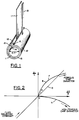
- the reference numeral 10 has been used therein to identify a tubular probe housing or pipe section.
- the pipe section 10 which is of a non-conducting unity magnetic permeability material, bounds a passage 11 for the flow therethrough of a fluid that is to be examined for the presence therein of various inclusions, such as magnetic and non-magnetic metallic particles.
- a probe member 12 of a highly electrically conductive material, such as copper, is arranged in such a manner as to be stationary relative to the pipe 10 and to circumferentially surround the passage 11.
- the probe member 12 may be embedded or potted in, or arranged around, the pipe section 10.
- the probe member 12 is constituted by a single turn coil and it has respective marginal portions 13 and 14 which bound a gap 15 with one another.
- the marginal portions 13 and 14 overlap one another, and a capacitor arrangement 16 is interposed in the gap 15 that is situated between the overlapping regions of the marginal portions 13 and 14.
- the capacitor arrangement 16 may include merely a layer or slab of dielectric material, in which case the overlapping regions of the marginal portions 13 and 14 constitute respective capacitor plates. However, more often than not, the surface areas of the overlapping regions of the marginal portions 13 and 14 are insufficient to provide the required capacitance.
- the capacitor arrangement 16 may be constituted by a single multilayer capacitor device, or preferably by a number of such multilayer devices which are distributed at predetermined, such as substantially identical, intervals along the gap 15 between the overlapping regions of the marginal portions 13 and 14 of the probe member 12. In any event, the capacitor arrangement 16 is situated at the gap 15 and is isolated from the passage 11.
- the marginal portions 13 and 14 have respective electric leads 17 and 18 connected to them.
- the electric leads 17 and 18 serve to supply alternating electric current to the marginal portions 13 and 14.
- the probe member 12 forms a parallel tank circuit with the capacitor arrangement 16.
- the capacitance of the capacitor arrangement 16 has a relatively high value.
- the value of this capacitance is chosen in such a manner with respect to the inductance of the probe member 12 as to achieve an inductance to capacitance ratio on the order of one to 4 or even less.
- the probe member 12 and the capacitor arrangement 15 form a resonator that is operated at resonance, as will be discussed in more detail later.
- the resonance characteristics of this resonator are influenced by the electromagnetic properties of inclusions present in the passage 11.
- this tank circuit has a high Q factor. It will be appreciated that important criteria to be considered when altering the dimensions of the probe member 12 (and/or the capacitance of the capacitor arrangement 16) include the preservation of this high Q factor, the preservation of uniformity of the magnetic field in the central probe passage region, and the maintenance of a low inductance to capacitance ratio.
- the resonator or tank circuit constituted by the probe member 12 and the capacitor arrangement 16 are constructed in the above-discussed manner for the detection of metallic debris in fluid flow systems.
- the thus obtained resonator has a very high quality factor, which means that the effective electrical impedance of such a resonator is greatly affected by even relatively small perturbations in the characteristic properties of the fluid present in the passage 11, as caused by entrained inclusions. This high sensitivity renders possible the detection of minute metallic particles then present in the passage 11.
- the filling and emptying of the passage in which the debris detection is to take place causes changes in the passage contents electromagnetic characteristics, namely the passage contents dielectric constant and hence the passage electric displacement field, as affecting the behavior of any surrounding coil or resonator.
- this kind of fluid level variation produces coil or resonator performance changes which inherently result in false indications of debris presence.
- the employment of a large fixed and isolated capacitance in the arrangement constructed in accordance with the present invention results in the second of the aforementioned two advantages, namely that the characteristic behavior of the resonator is only insignificantly affected by these changes in the electric displacement field existing in the passage 11.
- the reduction of this effect in the arrangement of the present invention is of such a magnitude that a .007" diameter ferromagnetic sphere passing through the passage 11 having a .75" inner diameter produces a signal of a magnitude three times that of a noise signal produced by completely emptying and filling the passage 11 with a typical lubricant.
- the achievement of the high Q factor means that, when the electric current supplied to the marginal portions 13 and 14 through the electric leads 17 and 18 alternates at such a frequency that the tank circuit operates at or close to resonance in the absence of any inclusions from the fluid present in the passage 11, any change in the characteristic response of the contents of the passage 11 caused, for instance, by the presence of metallic particles in the fluid flowing through tee passage 11, introduces an imbalance into the operation of this tank circuit in a manner dependent on the electromagnetic properties of such inclusions.
- metallic particles influence the electromagnetic field generated by the probe member 12 and thus the electric current flowing in the tank circuit differently, and to a much greater extent, than dielectric particles or other dielectric inclusions, and non-ferromagnetic metallic particles influence the electromagnetic field differently than ferromagnetic metallic particles, resulting in a different phase shift in each instance, while the magnitude of the change depends, by and large, on the size of the respective particle or inclusion.
- the elongated single turn coil configuration of the probe member 12 coupled with the low L/C ratio employed in the tank circuit, results in a situation where the electric displacement field within the probe member 12 is as low as possible in relation to the electric field existing in the isolated, fixed capacitance region, so that air bubbles which are frequently encountered in lubricants will affect the operation of the aforementioned tank circuit only to an insignificant extent, if at all.
- phase shift response of the tank circuit that is constructed in accordance with the present invention to changes in the electromagnetic properties of the contents of the passage 11 is diagrammatically depicted in Figure 2 of the drawing in which the point of origin O represents the conditions encountered when the passage 11 is filled with lubricating oil devoid of any inclusions.
- the dielectric constant of the fluid present in or flowing through the passage 11 changes, which may occur, for instance, due to replacement of the original dielectric fluid by another dielectric fluid
- both the relative resistivity ( R/R) and the relative impedance ( L/L) of the overall tank circuit (which includes the fluid present in the passage 11 in addition to the aforementioned tank circuit proper that is constituted by the probe member 12 and the capacitor arrangement 16) change generally to the same relatively small degree.
- both the relative impedance and the relative resistivity change in dependence on the size of the particle so as to be located on a curved line F which is applicable when the ferromagnetic particle is substantially spherical.
- point B of the curve F may be reached when the spherical ferromagnetic particle is about 7 mils in diameter, and the distance on the curve F from the point O will be lesser for smaller and greater for larger spherical ferromagnetic particles.
- FIG. 3 A circuit constructed in accordance with the present invention to gather and decipher the above information is presented in Figure 3 of the drawing where the same reference numerals as before have been used to identify corresponding parts (i.e. their electrical equivalents).
- the lead 18 from the tank circuit 12 and 16 is shown to be grounded, while the lead 17 is connected to one end of one transformer winding 19 of a driving and pickup transformer 20.
- the transformer 20 further includes another transformer winding 21 whose one end is grounded while the other end thereof is supplied with an alternating electric current from a voltage controlled oscillator (VCO) 22.
- VCO voltage controlled oscillator
- the alternating electromagnetic field generated by the other transformer winding 21 induces a correspondingly alternating electric current in the one transformer winding 19, and this latter electric current drives the tank circuit 12 and 16.
- the frequency of the alternating electric current issued by the oscillator VCO is such that the tank circuit 12 and 16 operates at or close to resonance.
- the alternating electric current is also supplied directly to one input of a first mixer 23, and through a 90° phase shifter 24 to one input of a second mixer 25.
- a line 26 supplies an alternating electric current derived from the one coil 19 and thus representative of the alternating electric current flowing through the one coil 19 and thus into and out of the tank circuit 12 and 16 to a pre-amplifier 27 from where the amplified electric current is supplied to another input of the first mixer 23, as well as to another input of the second mixer 25, where the respective incoming alternating electric currents are mixed with one another, with the result that respective in-phase and quadrature error signals indicative of the difference between the output frequency of the VCO 22 and the resonant frequency of the tank circuit 12 and 16 appear at respective outputs 28 and 29 of the mixers 23 and 25.
- These error signals are then filtered by respective low-pass filters 30 and 31 to obtain respective resistive (in-phase) and reactive (quadrature) error signals.
- the reactive error signal is supplied to a reactive error amplifier 32 which amplifies this reactive error signal, and this amplified reactive error signal is then supplied to an input of the VCO 22 which changes its operating (output) frequency in dependence on the magnitude of the amplified reactive error signal.
- the resistive error signal is fed to an input of a resistive error amplifier 33 which amplifies this resistive error signal, and this amplified resistive error signal is then supplied to an input of a voltage controlled resistor (VCR) 34 which is interposed between the other end of the one transformer winding 19 and the ground and whose resistance varies in dependence on the magnitude of the amplified resistive error signal.
- VCR voltage controlled resistor
- the resistive and reactive error amplifiers 33 and 32 are constructed to operate with relatively large time constants, so that the resistance of the VCR 34 and the frequency of the VCO 22 change gradually in response to relatively long-term changes, especially those due to temperature variations, of the resonance characteristics of the tank circuit and/or of the characteristic properties of the contents of the passage 11.
- short-lived changes in such characteristic properties such as those caused by the passage of individual metallic particles through the interior of the probe member 12, will leave the performance of the VCO 22 and of the VCR 34 virtually unaffected.
- the output signals of the low-pass filters 30 and 31 are also supplied to an evaluating circuit 35 which is constructed to evaluate the reactive and resistive error signals to determine therefrom the character and size of any metallic particle then present in the passage 11.
- An exemplary implementation of the evaluating circuit 35 is shown in Figure 3 of the drawing, but it is to be understood that the evaluating circuit 35 may have other configurations, depending on needs, or requirements for accuracy.
- the illustrated implementation of the evaluating circuit 35 incorporates a voltage divider 36 and a plurality of comparators 37a to 37n (n being any arbitrarily chosen integer) each of which has two inputs one of which is connected to an associated section of the voltage divider 36 while the other input is supplied with the filtered resistive error signal appearing at the output of the low-pass filter 30.
- the comparators 37a to 37n compare the filtered resistive error signal voltage with various reference voltage levels derived from the voltage divider 36, and that or those of the comparators 37a to 37n at which the filtered resistive error voltage exceeds the respective reference voltage issues an output signal or issue respective output signals which is or are then supplied to a drive circuit 38 of any known construction which drives a display 39. Furthermore, the filtered reactive error signal appearing at the output of the low-pass filter 32 is also supplied to the drive circuit 38 and is used to drive the display 39 accordingly.
- the drive circuit 38 and the display 39 may be constructed in any well-known manner to present a numerical indication of the value of the resistive error signal which, as a reference to Figure 2 will reveal, is indicative of the size of the respective metallic particle, whether such particle is ferromagnetic or non-ferromagnetic, and to present a simple, for instance on/off, indication of the sign of the reactive error signal to distinguish ferromagnetic metallic particles from non-ferromagnetic ones.
- the reactive and resistive error signals from the outputs of the filters 30 and 32 have been supplied to an oscillograph for recording thereat, and the thus recorded traces of the reactive and resistive error signals have been compared and evaluated in view of one another to determine both the size and the magnetic properties of respective particles.
- this cross-referencing procedure it is also contemplated to automate this cross-referencing procedure to determine the exact location of the response to the respective particle on the graph of Figure 2 with attendant more precise determination of the characteristics (size, magnetic properties) of the respective particle.
- the electric driving circuitry described above drives the resonator consisting of the probe member 12 and the capacitor arrangement 16 at or very close to resonance at all times.
- resonant frequency i.e. resonant frequency
- such short-lived perturbation detection and long-term change compensation is the result of the use and operation of the in-phase and quadrature detection and feedback arrangement which automatically nulls out a high frequency bridge circuit in response to long-term drifts in the resonant frequency and in the quality factor Q of the resonator, and which provides high sensitivity detection of transient changes caused by the passage of metallic debris particles through the passage 11.
- the in-phase and quadrature detection and feedback arrangement which automatically nulls out a high frequency bridge circuit in response to long-term drifts in the resonant frequency and in the quality factor Q of the resonator, and which provides high sensitivity detection of transient changes caused by the passage of metallic debris particles through the passage 11.
Landscapes
- Physics & Mathematics (AREA)
- Life Sciences & Earth Sciences (AREA)
- Engineering & Computer Science (AREA)
- Remote Sensing (AREA)
- General Physics & Mathematics (AREA)
- Chemical & Material Sciences (AREA)
- Geology (AREA)
- General Life Sciences & Earth Sciences (AREA)
- Environmental & Geological Engineering (AREA)
- Geophysics (AREA)
- Electromagnetism (AREA)
- Biochemistry (AREA)
- Health & Medical Sciences (AREA)
- Analytical Chemistry (AREA)
- Dispersion Chemistry (AREA)
- General Health & Medical Sciences (AREA)
- Immunology (AREA)
- Pathology (AREA)
- Investigating Or Analyzing Materials By The Use Of Magnetic Means (AREA)
- Powder Metallurgy (AREA)
- Manufacture Of Metal Powder And Suspensions Thereof (AREA)
- Investigating Or Analyzing Materials By The Use Of Electric Means (AREA)
Abstract
Claims (11)
- Sonde destinée à être utilisée pour détecter des particules métalliques individuelles transportées par un fluide s'écoulant en continu dans un passage allongé (11) et comportant une bobine d'induction (12) entourant le passage, caractérisée en ce que:
la bobine d'induction (12) est configurée électriquement comme un conducteur électrique (12) à une seule spire qui a une longueur prise dans la direction longitudinale du passage (11) qui est au moins égale au diamètre du conducteur (12) et comporte un espace (15) s'étendant sur toute la longueur du conducteur et séparant physiquement deux parties (13, 14) s'étendant longitudinalement du conducteur (12) l'une de l'autre et
des moyens (13, 14, 16) formant condensateur sont situés directement au niveau dudit espace (15), sont connectés électriquement entre lesdites parties (13, 14) dudit conducteur (12) et sont isolés du passage (11). - Sonde selon la revendication 1, caractérisée en ce que le conducteur électrique (12) et les moyens (13, 14, 16) formant condensateur constituent un circuit résonateur dont le rapport de l'inductance sur la capacité a une valeur d'au moins un à quatre.
- Ensemble de détection de particules métalliques individuelles transportées par un fluide s'écoulant en continu dans un passage allongé et comportant une sonde selon la revendication 1 ou 2, la sonde étant alimentée par un courant électrique alternatif par l'intermédiaire de moyens (22) de pilotage commandés par des moyens formant commande, caractérisé en ce que:
les moyens de commande assurent la commande des moyens de pilotage (22) de manière telle que le courant alternatif transmis par ceux-ci a une fréquence correspondant à peu près à la fréquence de résonance électrique du résonateur électrique constitué par le conducteur électrique (12) et les moyens (13, 14, 16) formant condensateur, sous l'influence de la présence d'inclusions dans le liquide s'écoulant à travers le passage (11), et
des moyens (23 à 25, 30, 31, 37a...37n) pour déterminer le caractère d'au moins une particule métallique quelconque alors présente dans ledit passage (11) à partir des variations dudit courant électrique alternatif qui reflètent l'influence de ladite particule métallique sur ladite caractéristique de résonance. - Ensemble selon la revendication 3, caractérisé en ce que la bobine d'induction (12) est constituée par un tube fendu (12) qui s'étend autour dudit passage (11) et comporte deux parties marginales (13, 14) délimitant ledit espace (15),
en ce que les moyens (13, 14, 16) formant condensateur comportent au moins deux surfaces de condensateur dirigées mutuellement l'une vers l'autre, chacune étant connectée électriquement à l'une desdites parties marginales (13, 14) de ladite bobine (12) et au moins une couche diélectrique 16 est interposée entre lesdites surfaces de condensateur,
en ce que la bobine (12) et lesdits moyens (13, 14, 16) formant condensateur forment un circuit bouchon ayant des caractéristiques de résonance qui sont influencées par une inclusion quelconque alors présente dans ledit passage (11) d'une manière fonction des propriétés électromagnétiques de ladite inclusion, et
en ce que les moyens de détermination (23 à 25, 30, 31, 37a...37n) déterminent les caractéristiques magnétiques et les dimensions des inclusions métalliques à partir de signaux d'erreurs (28, 29) émis par les moyens de commande et représentatifs de l'influence de telles inclusions sur ladite fréquence de résonance. - Ensemble selon la revendication 3 ou 4, caractérisé en ce que lesdits moyens formant condensateur comportent plusieurs condensateurs individuels répartis le long dudit espace.
- Ensemble selon la revendication 5, caractérisé en ce que lesdits condensateurs sont des condensateurs en forme de pastilles.
- Ensemble selon l'une quelconque des revendications 4 à 6, caractérisé en ce que les parties marginales (13, 14) de ladite bobine (12) de sonde se recouvrent l'une l'autre pour constituer les plaques respectives (13, 14) de condensateur desdits moyens (13, 14, 16) formant condensateur, et en ce que ledit élément diélectrique (16) est interposé entre lesdites parties marginales se recouvrant (13, 14).
- Ensemble selon l'une quelconque des revendications 4 à 7, caractérisé en ce que lesdites parties marginales (13, 14) de ladite bobine (12) se recouvrent l'une l'autre et en ce que ledit élément diélectrique (16) est interposé entre lesdites parties marginales se recouvrant (13, 14).
- Ensemble selon l'une quelconque des revendications 3 à 8, caractérisé en ce que lesdits moyens de commande comportent des moyens (20, 22) destinés à appliquer un champ d'excitation électrique alternatif à ladite bobine (12) et en ce que lesdits moyens de détermination (23 à 25, 30, 31, 37a...37n) comportent des moyens (23, 25) pour mélanger une tension alternative dudit courant électrique alternatif de manière séparée en phase et en quadrature, avec une tension alternative représentative dudit champ d'excitation électrique alternatif, respectivement, pour obtenir des signaux d'erreur résistive (28) et réactive (29) respectifs lorsqu'une particule métallique quelconque est présente dans ledit passage (11) et des moyens (35) pour évaluer lesdits signaux d'erreur résistive (28) et réactive (29) pour obtenir à partir de ceux-ci une information relative à la dimension et aux propriétés magnétiques d'une telle particule métallique.
- Ensemble selon la revendication 9, caractérisé en ce que lesdits moyens (20, 22) d'application comportent un oscillateur (22) commandé en tension comportant une entrée de commande, et comportant en outre des moyens (24, 25, 31, 32) de rétroaction d'erreur réactive destinés à envoyer ledit signal d'erreur réactive (29) vers ladite entrée de commande dudit oscillateur (22) commandé en tension pour commander la fréquence de ce dernier pour qu'elle suive celle dudit circuit bouchon (12, 16).
- Ensemble selon la revendication 10, caractérisé en ce qu'il comporte une résistance (34) commandée en tension agencée en circuit avec ladite sonde (12, 13, 16) et ayant une entrée de commande, et des moyens (26, 27, 23, 30, 33) de rétroaction d'erreur résistive destinés à envoyer ledit signal d'erreur résistive (28) vers ladite entrée de commande de ladite résistance (34) commandée en tension pour compenser les changements de résistance efficace dudit circuit bouchon (12, 16).
Applications Claiming Priority (3)
| Application Number | Priority Date | Filing Date | Title |
|---|---|---|---|
| US290531 | 1988-12-27 | ||
| US07/290,531 US4926120A (en) | 1988-12-27 | 1988-12-27 | In-line metallic debris particle detection system |
| PCT/US1989/005869 WO1990007705A1 (fr) | 1988-12-27 | 1989-12-22 | Agencement servant a detecter la presence de particules metalliques portees par un fluide |
Publications (2)
| Publication Number | Publication Date |
|---|---|
| EP0451209A1 EP0451209A1 (fr) | 1991-10-16 |
| EP0451209B1 true EP0451209B1 (fr) | 1994-08-10 |
Family
ID=23116427
Family Applications (1)
| Application Number | Title | Priority Date | Filing Date |
|---|---|---|---|
| EP90901963A Expired - Lifetime EP0451209B1 (fr) | 1988-12-27 | 1989-12-22 | Agencement servant a detecter la presence de particules metalliques portees par un fluide |
Country Status (10)
| Country | Link |
|---|---|
| US (1) | US4926120A (fr) |
| EP (1) | EP0451209B1 (fr) |
| JP (1) | JP2865857B2 (fr) |
| KR (1) | KR0150205B1 (fr) |
| AR (1) | AR243279A1 (fr) |
| AU (2) | AU635516B2 (fr) |
| DE (1) | DE68917480T2 (fr) |
| IL (1) | IL92887A (fr) |
| TR (1) | TR25614A (fr) |
| WO (1) | WO1990007705A1 (fr) |
Cited By (3)
| Publication number | Priority date | Publication date | Assignee | Title |
|---|---|---|---|---|
| EP1933129A2 (fr) | 2006-12-15 | 2008-06-18 | Prüftechnik Dieter Busch Ag | Dispositif et procédé destinés à détecter des particules dans un liquide s'écoulant |
| EP2028474A2 (fr) | 2007-08-21 | 2009-02-25 | Prüftechnik Dieter Busch Ag | Dispositif et procédé destinés à détecter des particules dans un liquide s'écoulant |
| EP1401763B2 (fr) † | 2001-07-03 | 2010-02-10 | Facultés Universitaires Notre-Dame de la Paix | Supports catalytiques et nanotubes de carbone produits sur ces supports |
Families Citing this family (30)
| Publication number | Priority date | Publication date | Assignee | Title |
|---|---|---|---|---|
| US4926120A (en) * | 1988-12-27 | 1990-05-15 | United Technologies Corporation | In-line metallic debris particle detection system |
| US5041856A (en) * | 1988-12-27 | 1991-08-20 | United Technologies Corporation | In-line metallic debris particle detection probe and resonant evaluation system utilizing the same |
| US5235269A (en) * | 1990-03-19 | 1993-08-10 | Yokogawa Electric Corporation | Waveform measuring device |
| US5760298A (en) * | 1990-11-28 | 1998-06-02 | Stewart Hughes Ltd. | System and method for monitoring debris in a fluid |
| US5315243A (en) * | 1992-04-06 | 1994-05-24 | Her Majesty The Queen In Right Of Canada, As Represented By The Minister Of National Defence | Detection and discrimination between ferromagnetic and non-ferromagnetic conductive particles in a fluid |
| US5444367A (en) * | 1992-04-06 | 1995-08-22 | Minister Of National Defence | Method and apparatus for detecting particles in a fluid having coils isolated from external vibrations |
| US5696331A (en) * | 1992-06-26 | 1997-12-09 | Kabushiki Kaisha Komatsu Seisakusho | Apparatus for detecting metal powder amount in hydraulic circuit |
| US5680201A (en) * | 1992-10-15 | 1997-10-21 | Carrier Corporation | Apparatus for including tank circuit with shielded, single turn coil, detecting passage of end of workpiece |
| US5357197A (en) * | 1992-11-10 | 1994-10-18 | Smiths Industries | Inductive debris monitor with multi-turn detector |
| US5485083A (en) * | 1993-10-28 | 1996-01-16 | Smiths Industries | Transformer coupled in-line metallic debris sensor |
| GB9417763D0 (en) * | 1994-08-31 | 1994-10-19 | Univ Edinburgh | Debris monitoring transducer |
| US5565768A (en) * | 1994-11-10 | 1996-10-15 | Smiths, Industries Aerospace & Defense Systems, Inc. | Apparatus for detecting metallic debris in dielectric fluid having an indirectly heated thermistor for balancing a bridge network |
| US5742234A (en) * | 1995-02-28 | 1998-04-21 | Vickers, Inc. | Particle detection and destruction in fluid systems |
| US5608316A (en) * | 1995-08-21 | 1997-03-04 | Caterpillar Inc. | Apparatus for detecting particles in a fluid and a method for operating same |
| US5608315A (en) * | 1995-08-21 | 1997-03-04 | Caterpillar Inc. | Apparatus for detecting particles in a fluid and a method for operating same |
| RU2119985C1 (ru) * | 1997-07-31 | 1998-10-10 | Орловский государственный технический университет | Способ обнаружения металлических частиц в движущемся материале |
| US6867603B2 (en) * | 2002-12-04 | 2005-03-15 | Delphi Technologies, Inc. | Method for measuring high frequency resistance in diesel engine lubrication oil |
| GB0317675D0 (en) * | 2003-07-29 | 2003-09-03 | Rolls Royce Plc | Engine monitoring arrangement |
| WO2005060653A2 (fr) * | 2003-12-18 | 2005-07-07 | E.I. Dupont De Nemours And Company | Sonde inductive possedant un element de detection a boucle ou a ligne de transmission adaptee, et procedes et systeme associes |
| US7794663B2 (en) * | 2004-02-19 | 2010-09-14 | Axcelis Technologies, Inc. | Method and system for detection of solid materials in a plasma using an electromagnetic circuit |
| US7034549B2 (en) * | 2004-03-31 | 2006-04-25 | The United States Of America As Represented By The Secretary Of The Navy | Device to detect and measure the concentration and characterization of airborne conductive or dielectric particles |
| WO2006031563A2 (fr) * | 2004-09-10 | 2006-03-23 | E.I. Dupont De Nemours And Company | Procede de detection d'une interface entre des premiere et seconde strates de materiaux |
| WO2006031564A2 (fr) * | 2004-09-10 | 2006-03-23 | E.I. Dupont De Nemours And Company | Appareil de detection permettant de detecter une interface entre des premieres et des secondes strates de materiaux |
| EP2071364B1 (fr) | 2006-09-26 | 2013-03-27 | NTN Corporation | Capteur pour la détection de morceaux cassés |
| US8256277B2 (en) * | 2009-06-11 | 2012-09-04 | United Technologies Corporation | Gas turbine engine debris monitoring arrangement |
| DE102012013255A1 (de) * | 2012-07-03 | 2014-05-08 | Hydac Filter Systems Gmbh | Verfahren zum Detektieren von Partikeln in einem Fluidstrom |
| US10295499B2 (en) | 2017-02-16 | 2019-05-21 | Spectro Scientific, Inc. | Ferrous metals measuring magnetometer system and method |
| CN108008453A (zh) * | 2017-11-23 | 2018-05-08 | 中国航发沈阳黎明航空发动机有限责任公司 | 一种燃气轮机滑油系统金属屑末在线监测系统 |
| CN109813761B (zh) * | 2019-03-12 | 2022-02-08 | 大连海事大学 | 一种电感磁塞式油液在线监测装置 |
| US11982665B2 (en) | 2020-11-20 | 2024-05-14 | Dodge Industrial, Inc. | Oil quality sensor |
Family Cites Families (18)
| Publication number | Priority date | Publication date | Assignee | Title |
|---|---|---|---|---|
| US2772393A (en) * | 1952-12-23 | 1956-11-27 | California Research Corp | Water-in-oil detector |
| GB1316793A (en) * | 1969-06-03 | 1973-05-16 | Euratom | Apparatusfor the detection of bubbles in a liquid metal and for the determination of metal particles in tubes |
| GB1348881A (en) * | 1970-02-27 | 1974-03-27 | Smiths Industries Ltd | Particle detection apparatus |
| SU741216A1 (ru) * | 1975-02-28 | 1980-06-15 | Предприятие П/Я В-2015 | Металлоискатель |
| SU761964A1 (ru) * | 1978-03-13 | 1980-09-07 | Khabarovsk Polt Inst | УСТРОЙСТВО ДЛЯ ОПРВДЁЛЁНТС^""* '· КОНЦЕНТРАЦИИ ФЕРРОМАГНИТНЫХ ЧАСТИЦ ' ’ В НЁЭЛЦКТРОПРОВОДЯЩИХ СРЕДАХ |
| US4176545A (en) * | 1978-06-16 | 1979-12-04 | Oddo Luigi G | Electronic engine wear detector |
| GB2101330B (en) * | 1981-06-22 | 1985-02-27 | Smiths Industries Plc | Detecting particles in flowing fluids |
| US4435680A (en) * | 1981-10-09 | 1984-03-06 | Medical College Of Wisconsin | Microwave resonator structure |
| US4446429A (en) * | 1981-10-09 | 1984-05-01 | Medical College Of Wisconsin | Microwave resonator |
| US4504788A (en) * | 1982-09-03 | 1985-03-12 | The Medical College Of Wisconsin, Inc. | Enclosed loop-gap resonator |
| US4553094A (en) * | 1983-06-20 | 1985-11-12 | K. J. Law Engineers, Inc. | Method and apparatus for measuring conductivity using eddy currents with temperature compensation feature |
| US4623835A (en) * | 1984-03-14 | 1986-11-18 | Medical College Of Wisconsin, Inc. | Web thickness sensor using loop-gap resonator |
| US4570137A (en) * | 1984-09-04 | 1986-02-11 | Motorola, Inc. | Lumped-mode resonator |
| US4654598A (en) * | 1985-03-08 | 1987-03-31 | The Regents Of The University Of California | Dielectric methods and apparatus for in situ prediction of porosity and specific surface area (i.e., soil type) and for detection of hydrocarbons, hazardous waste materials, and the degree of melting of ice and to predict in situ stress-strain behavior |
| US4721913A (en) * | 1985-05-08 | 1988-01-26 | Mcw Research Foundation, Inc. | NMR local coil network |
| US4724389A (en) * | 1985-05-08 | 1988-02-09 | Medical College Of Wisconsin, Inc. | Loop-gap resonator for localized NMR imaging |
| US4839602A (en) * | 1986-11-04 | 1989-06-13 | Philip Morris Incorporated | Means for detecting metal in a stream of particulate matter |
| US4926120A (en) * | 1988-12-27 | 1990-05-15 | United Technologies Corporation | In-line metallic debris particle detection system |
-
1988
- 1988-12-27 US US07/290,531 patent/US4926120A/en not_active Expired - Lifetime
-
1989
- 1989-12-22 DE DE68917480T patent/DE68917480T2/de not_active Expired - Fee Related
- 1989-12-22 EP EP90901963A patent/EP0451209B1/fr not_active Expired - Lifetime
- 1989-12-22 KR KR1019900701894A patent/KR0150205B1/ko not_active Expired - Fee Related
- 1989-12-22 WO PCT/US1989/005869 patent/WO1990007705A1/fr not_active Ceased
- 1989-12-22 JP JP2502116A patent/JP2865857B2/ja not_active Expired - Fee Related
- 1989-12-22 AU AU48487/90A patent/AU635516B2/en not_active Ceased
- 1989-12-26 IL IL9288789A patent/IL92887A/en not_active IP Right Cessation
- 1989-12-27 AR AR89315817A patent/AR243279A1/es active
- 1989-12-27 TR TR89/1045A patent/TR25614A/xx unknown
-
1993
- 1993-02-10 AU AU32963/93A patent/AU656840B2/en not_active Ceased
Non-Patent Citations (1)
| Title |
|---|
| Derwent's abstract no. B 6 038 D/08, SU 741 216 * |
Cited By (6)
| Publication number | Priority date | Publication date | Assignee | Title |
|---|---|---|---|---|
| EP1401763B2 (fr) † | 2001-07-03 | 2010-02-10 | Facultés Universitaires Notre-Dame de la Paix | Supports catalytiques et nanotubes de carbone produits sur ces supports |
| EP1933129A2 (fr) | 2006-12-15 | 2008-06-18 | Prüftechnik Dieter Busch Ag | Dispositif et procédé destinés à détecter des particules dans un liquide s'écoulant |
| US8354836B2 (en) | 2006-12-15 | 2013-01-15 | Prüftechnik Dieter Busch AG | Device and process for detecting particles in a flowing liquid |
| EP2028474A2 (fr) | 2007-08-21 | 2009-02-25 | Prüftechnik Dieter Busch Ag | Dispositif et procédé destinés à détecter des particules dans un liquide s'écoulant |
| DE102007039434A1 (de) | 2007-08-21 | 2009-02-26 | Prüftechnik Dieter Busch AG | Verfahren und Vorrichtung zum Erfassen von Partikeln in einer strömenden Flüssigkeit |
| US7956601B2 (en) | 2007-08-21 | 2011-06-07 | Prueftechnik Dieter Busch Ag | Device and process for detecting particles in a flowing liquid |
Also Published As
| Publication number | Publication date |
|---|---|
| KR0150205B1 (ko) | 1998-12-01 |
| AU4848790A (en) | 1990-08-01 |
| WO1990007705A1 (fr) | 1990-07-12 |
| US4926120A (en) | 1990-05-15 |
| IL92887A0 (en) | 1990-09-17 |
| EP0451209A1 (fr) | 1991-10-16 |
| JP2865857B2 (ja) | 1999-03-08 |
| JPH04502513A (ja) | 1992-05-07 |
| AU3296393A (en) | 1993-04-08 |
| AU656840B2 (en) | 1995-02-16 |
| TR25614A (tr) | 1993-04-30 |
| KR920701809A (ko) | 1992-08-12 |
| AR243279A1 (es) | 1993-07-30 |
| DE68917480D1 (de) | 1994-09-15 |
| DE68917480T2 (de) | 1994-12-15 |
| IL92887A (en) | 1994-10-07 |
| AU635516B2 (en) | 1993-03-25 |
Similar Documents
| Publication | Publication Date | Title |
|---|---|---|
| EP0451209B1 (fr) | Agencement servant a detecter la presence de particules metalliques portees par un fluide | |
| US5041856A (en) | In-line metallic debris particle detection probe and resonant evaluation system utilizing the same | |
| US5811664A (en) | Debris monitoring | |
| US5001424A (en) | Apparatus for measuring magnetic particles suspended in a fluid based on fluctuations in an induced voltage | |
| US4731578A (en) | Electrical sensing system for measuring ferrous particles within a fluid | |
| EP3349000B1 (fr) | Appareil de détection | |
| US5315243A (en) | Detection and discrimination between ferromagnetic and non-ferromagnetic conductive particles in a fluid | |
| US3233173A (en) | Method of determining the volume of particles in a mixture | |
| EP0124042A2 (fr) | Détecteur électromagnétique pour des matériaux métalliques | |
| US5061364A (en) | Diagnostic filter for detecting conductive and semiconductive particles in a fluid stream | |
| US6051970A (en) | System and method for measuring the magnetic conductive properties of a test fluid | |
| GB2101330A (en) | Detecting particles in flowing fluids | |
| US5118410A (en) | Debris collecting and measuring device with induction coil screen | |
| CN116297053B (zh) | 一种用于润滑油磨粒检测的复合磁场传感器结构、及其制作方法和使用方法 | |
| US3443211A (en) | Magnetometer inspection apparatus for ferromagnetic objects | |
| CA2006796C (fr) | Sonde de detection en ligne de particules de debris metalliques et systeme d'evaluation par resonance l'utilisant | |
| Markova | Diagnostics of the wear of tribological assemblies using an inductive wear debris counter | |
| CA2117871C (fr) | Detection des particules presentes dans un fluide | |
| RU2234080C1 (ru) | Устройство для детектирования металлических частиц в потоке смазочного материала | |
| SU987471A1 (ru) | Устройство дл определени концентрации металлических примесей в смазочных маслах механизмов | |
| JPH06129225A (ja) | 金属砕片感知装置 |
Legal Events
| Date | Code | Title | Description |
|---|---|---|---|
| PUAI | Public reference made under article 153(3) epc to a published international application that has entered the european phase |
Free format text: ORIGINAL CODE: 0009012 |
|
| 17P | Request for examination filed |
Effective date: 19910624 |
|
| AK | Designated contracting states |
Kind code of ref document: A1 Designated state(s): BE CH DE FR GB IT LI NL SE |
|
| ITCL | It: translation for ep claims filed |
Representative=s name: FIAMMENGHI FIAMMENGHI RACHELI |
|
| TCNL | Nl: translation of patent claims filed | ||
| EL | Fr: translation of claims filed | ||
| DET | De: translation of patent claims | ||
| 17Q | First examination report despatched |
Effective date: 19930210 |
|
| ITF | It: translation for a ep patent filed | ||
| GRAA | (expected) grant |
Free format text: ORIGINAL CODE: 0009210 |
|
| AK | Designated contracting states |
Kind code of ref document: B1 Designated state(s): BE CH DE FR GB IT LI NL SE |
|
| REF | Corresponds to: |
Ref document number: 68917480 Country of ref document: DE Date of ref document: 19940915 |
|
| ET | Fr: translation filed | ||
| EAL | Se: european patent in force in sweden |
Ref document number: 90901963.0 |
|
| PLBE | No opposition filed within time limit |
Free format text: ORIGINAL CODE: 0009261 |
|
| STAA | Information on the status of an ep patent application or granted ep patent |
Free format text: STATUS: NO OPPOSITION FILED WITHIN TIME LIMIT |
|
| 26N | No opposition filed | ||
| PGFP | Annual fee paid to national office [announced via postgrant information from national office to epo] |
Ref country code: CH Payment date: 20001117 Year of fee payment: 12 |
|
| PGFP | Annual fee paid to national office [announced via postgrant information from national office to epo] |
Ref country code: SE Payment date: 20001120 Year of fee payment: 12 |
|
| PGFP | Annual fee paid to national office [announced via postgrant information from national office to epo] |
Ref country code: NL Payment date: 20001123 Year of fee payment: 12 |
|
| PGFP | Annual fee paid to national office [announced via postgrant information from national office to epo] |
Ref country code: BE Payment date: 20001218 Year of fee payment: 12 |
|
| PG25 | Lapsed in a contracting state [announced via postgrant information from national office to epo] |
Ref country code: SE Free format text: LAPSE BECAUSE OF NON-PAYMENT OF DUE FEES Effective date: 20011223 |
|
| PG25 | Lapsed in a contracting state [announced via postgrant information from national office to epo] |
Ref country code: LI Free format text: LAPSE BECAUSE OF NON-PAYMENT OF DUE FEES Effective date: 20011231 Ref country code: CH Free format text: LAPSE BECAUSE OF NON-PAYMENT OF DUE FEES Effective date: 20011231 Ref country code: BE Free format text: LAPSE BECAUSE OF NON-PAYMENT OF DUE FEES Effective date: 20011231 |
|
| REG | Reference to a national code |
Ref country code: GB Ref legal event code: IF02 |
|
| BERE | Be: lapsed |
Owner name: UNITED TECHNOLOGIES CORP. Effective date: 20011231 |
|
| PG25 | Lapsed in a contracting state [announced via postgrant information from national office to epo] |
Ref country code: NL Free format text: LAPSE BECAUSE OF NON-PAYMENT OF DUE FEES Effective date: 20020701 |
|
| EUG | Se: european patent has lapsed |
Ref document number: 90901963.0 |
|
| REG | Reference to a national code |
Ref country code: CH Ref legal event code: PL |
|
| NLV4 | Nl: lapsed or anulled due to non-payment of the annual fee |
Effective date: 20020701 |
|
| PGFP | Annual fee paid to national office [announced via postgrant information from national office to epo] |
Ref country code: FR Payment date: 20041111 Year of fee payment: 16 |
|
| PGFP | Annual fee paid to national office [announced via postgrant information from national office to epo] |
Ref country code: GB Payment date: 20041116 Year of fee payment: 16 |
|
| PGFP | Annual fee paid to national office [announced via postgrant information from national office to epo] |
Ref country code: DE Payment date: 20041117 Year of fee payment: 16 |
|
| PG25 | Lapsed in a contracting state [announced via postgrant information from national office to epo] |
Ref country code: IT Free format text: LAPSE BECAUSE OF NON-PAYMENT OF DUE FEES Effective date: 20051222 Ref country code: GB Free format text: LAPSE BECAUSE OF NON-PAYMENT OF DUE FEES Effective date: 20051222 |
|
| PG25 | Lapsed in a contracting state [announced via postgrant information from national office to epo] |
Ref country code: DE Free format text: LAPSE BECAUSE OF NON-PAYMENT OF DUE FEES Effective date: 20060701 |
|
| GBPC | Gb: european patent ceased through non-payment of renewal fee |
Effective date: 20051222 |
|
| PG25 | Lapsed in a contracting state [announced via postgrant information from national office to epo] |
Ref country code: FR Free format text: LAPSE BECAUSE OF NON-PAYMENT OF DUE FEES Effective date: 20060831 |
|
| REG | Reference to a national code |
Ref country code: FR Ref legal event code: ST Effective date: 20060831 |