EP1933129A2 - Dispositif et procédé destinés à détecter des particules dans un liquide s'écoulant - Google Patents
Dispositif et procédé destinés à détecter des particules dans un liquide s'écoulant Download PDFInfo
- Publication number
- EP1933129A2 EP1933129A2 EP07024192A EP07024192A EP1933129A2 EP 1933129 A2 EP1933129 A2 EP 1933129A2 EP 07024192 A EP07024192 A EP 07024192A EP 07024192 A EP07024192 A EP 07024192A EP 1933129 A2 EP1933129 A2 EP 1933129A2
- Authority
- EP
- European Patent Office
- Prior art keywords
- particles
- coil
- receiver
- difference signal
- particle
- Prior art date
- Legal status (The legal status is an assumption and is not a legal conclusion. Google has not performed a legal analysis and makes no representation as to the accuracy of the status listed.)
- Granted
Links
- 239000002245 particle Substances 0.000 title claims abstract description 116
- 238000000034 method Methods 0.000 title claims description 31
- 239000012530 fluid Substances 0.000 title abstract description 3
- 238000011156 evaluation Methods 0.000 claims abstract description 12
- 239000007788 liquid Substances 0.000 claims description 21
- 239000000314 lubricant Substances 0.000 claims description 10
- 230000001939 inductive effect Effects 0.000 claims description 9
- 238000001514 detection method Methods 0.000 claims description 4
- 238000007619 statistical method Methods 0.000 claims 2
- 230000005540 biological transmission Effects 0.000 claims 1
- 230000001419 dependent effect Effects 0.000 claims 1
- 239000010687 lubricating oil Substances 0.000 claims 1
- 238000005259 measurement Methods 0.000 description 16
- 238000005314 correlation function Methods 0.000 description 3
- 239000000463 material Substances 0.000 description 3
- 239000013528 metallic particle Substances 0.000 description 3
- 238000012360 testing method Methods 0.000 description 3
- 244000089486 Phragmites australis subsp australis Species 0.000 description 2
- 238000004364 calculation method Methods 0.000 description 2
- 238000012937 correction Methods 0.000 description 2
- 230000006698 induction Effects 0.000 description 2
- 230000015572 biosynthetic process Effects 0.000 description 1
- 238000009529 body temperature measurement Methods 0.000 description 1
- 238000012512 characterization method Methods 0.000 description 1
- 230000008878 coupling Effects 0.000 description 1
- 238000010168 coupling process Methods 0.000 description 1
- 238000005859 coupling reaction Methods 0.000 description 1
- 238000013016 damping Methods 0.000 description 1
- 230000003247 decreasing effect Effects 0.000 description 1
- 230000007547 defect Effects 0.000 description 1
- 238000010586 diagram Methods 0.000 description 1
- 238000006073 displacement reaction Methods 0.000 description 1
- 230000000694 effects Effects 0.000 description 1
- 230000005672 electromagnetic field Effects 0.000 description 1
- 230000007613 environmental effect Effects 0.000 description 1
- 230000002349 favourable effect Effects 0.000 description 1
- 239000012535 impurity Substances 0.000 description 1
- 229910001338 liquidmetal Inorganic materials 0.000 description 1
- 238000005461 lubrication Methods 0.000 description 1
- 230000035699 permeability Effects 0.000 description 1
- 230000010363 phase shift Effects 0.000 description 1
- 230000035945 sensitivity Effects 0.000 description 1
- 238000000926 separation method Methods 0.000 description 1
- 230000001629 suppression Effects 0.000 description 1
- 238000002604 ultrasonography Methods 0.000 description 1
Images


Classifications
-
- G—PHYSICS
- G01—MEASURING; TESTING
- G01N—INVESTIGATING OR ANALYSING MATERIALS BY DETERMINING THEIR CHEMICAL OR PHYSICAL PROPERTIES
- G01N15/00—Investigating characteristics of particles; Investigating permeability, pore-volume or surface-area of porous materials
- G01N15/10—Investigating individual particles
- G01N15/1031—Investigating individual particles by measuring electrical or magnetic effects
-
- G—PHYSICS
- G01—MEASURING; TESTING
- G01N—INVESTIGATING OR ANALYSING MATERIALS BY DETERMINING THEIR CHEMICAL OR PHYSICAL PROPERTIES
- G01N33/00—Investigating or analysing materials by specific methods not covered by groups G01N1/00 - G01N31/00
- G01N33/26—Oils; Viscous liquids; Paints; Inks
- G01N33/28—Oils, i.e. hydrocarbon liquids
- G01N33/2835—Specific substances contained in the oils or fuels
- G01N33/2858—Metal particles
-
- G—PHYSICS
- G01—MEASURING; TESTING
- G01N—INVESTIGATING OR ANALYSING MATERIALS BY DETERMINING THEIR CHEMICAL OR PHYSICAL PROPERTIES
- G01N15/00—Investigating characteristics of particles; Investigating permeability, pore-volume or surface-area of porous materials
- G01N15/10—Investigating individual particles
- G01N2015/1024—Counting particles by non-optical means
-
- G—PHYSICS
- G01—MEASURING; TESTING
- G01N—INVESTIGATING OR ANALYSING MATERIALS BY DETERMINING THEIR CHEMICAL OR PHYSICAL PROPERTIES
- G01N15/00—Investigating characteristics of particles; Investigating permeability, pore-volume or surface-area of porous materials
- G01N15/10—Investigating individual particles
- G01N2015/1027—Determining speed or velocity of a particle
Definitions
- the invention relates to a method and a device for detecting electrically conductive particles in a liquid flowing in a pipe by means of eddy currents.
- a device is sold, in which three coils are arranged one behind the other in the flow direction, wherein the first and the last coil as transmitter coils and the middle coil as Receiver coil act to detect the passage of electrically conductive particles from a lubricant circuit. The first and the last coil are reversed poled.
- electrically conductive particles in a liquid passing through the coils cause eddy current losses, which in turn are reflected in a measurable impedance change of the coils.
- electrically conductive particles can be detected in a liquid flowing in a pipe by means of an inductive coil arrangement. This is particularly advantageous if one wants to detect the concentration of metallic particles in a lubricant circuit of a machine in order to conclude on the machine condition (the concentration of the metallic particles is usually a measure of the wear of the machine).
- the transmitter coil and the receiver coils form a transformer arrangement and the transmitter coil is arranged in the region of the receiver coils, all coils are arranged close to each other and thus substantially the same environmental influences, e.g. are exposed to temperature, which increases the accuracy of measurement.
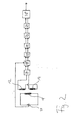
- a pipe section 10 is surrounded by a first inductive receiver coil 12 and a second inductive receiver coil 14 arranged spaced apart in the axial direction so that a liquid 16 flowing in the pipe section 10 flows through the coils 12 and 14 in the axial direction.
- the axial distance between the two Coils 12, 14 and the axial dimension of the coils 12, 14 may be for example 2 mm.
- the two receiver coils 12, 14 are externally surrounded by a transmitter coil 18 which is arranged coaxially with the two coils 12, 14 and has a larger diameter than this.
- the axial dimension of the transmitter coil 18 is such that the two receiver coils 12, 14 are completely disposed within the transmitter coil 18.
- the extension of the transmitter coil 18 in the axial direction is at least twice as large as the axial extent of the arrangement of the receiver coils 12, 14, ie distance plus axial extension of the coils 12, 14.
- the coils 12, 14, 18 are in one the pipe section 10 enclosing housing 22 is arranged.
- the tubing 10 is part of a lubrication circuit of a machine, with the fluid 16 then being a lubricant in which metallic particles are present, which are typically attrition from moving parts of the machine.
- a typical value for the lubricant flow in the main flow is 10 liters / min. At much higher throughputs, it is useful not to measure in the main stream, but in a side stream.
- the two receiver coils 12, 14 are subtractively connected as a differential coil, ie are arranged in opposite directions, so that in the two coils 12, 14, a voltage of the same magnitude but opposite sign is induced .
- the transformer core is formed in such an arrangement of the coils 12, 14, 18 passing through materials or media, ie air, the housing 22, the tube 10, and the liquid 16 with the particles 20.
- the impedance difference of the coils 12, 14, i. the difference between the impedance of the two coils 12, 14 caused by the instantaneous presence of a particle 20 in one of the two coils 12, 14 (the particles 20 are substantially smaller than the spacing of the coils 12, 14) is determined by that of the coils 12 and 14 14 output measured signal.
- the transmitter coil 18 is acted upon by means of an oscillator 24 with a suitable alternating voltage, which is preferably in the range between 20 and 500 kHz, to generate a measuring signal of the receiver coils 12, 14 via eddy currents induced in the electrically conductive particles 20.
- the measurement signal delivered to the coils 12, 14 is supplied via an input stage 26 to a preamplifier of a unit 28, in which a demodulation with respect to the transmitter frequency of the oscillator 24 takes place, either an absolute value or alternatively a two-channel demodulation with a phase shift of 90 ° between the two channels takes place. In the latter case, the subsequent signal path is then formed two channels. This variant is in Fig. 2 shown.
- the demodulated signal is then passed through a filter 30, which filters out the carrier frequency by means of a low-pass filter and the coil fault voltage (in principle results in a differential coil as a result of difference formation (the individual coils of the differential coil are never the same in practice) the so-called coil fault voltage, which can exceed the actual difference signal, for example by up to three orders of magnitude).
- the signal thus filtered is then amplified by means of an amplifier 32 and passed through a preferably variable bandpass filter 34, which filters out any interferences superimposed on the signal.
- the bandpass filtered signal passes through a phase adjuster 36, which allows to adjust the phase position of the signal in a manner favorable for the evaluation before the signal is fed to an evaluation unit 38, which in a conventional manner, the amplitude and the phase position of the particles 20 derived measuring signal determined.
- This signal can be displayed for example in an orbital representation on a screen.
- the evaluation unit 38 is designed such that a count of the detected particle passages takes place in order to be able to infer the particle concentration in the liquid 16, and thus possibly the machine condition.
- a multi-differential coil which has, for example, four receiver coils, each of the two receiver coils 12 and 14 of the normal differential coil being replaced by two receiver coils connected in opposition to each other.
- a multi-differential coil has a better noise suppression, ie a better signal-to-noise ratio, than a normal difference coil, and the signal shape is more pronounced.
- the structure is more complex and the signal amplitudes are smaller. Also, you may get annoying pre- and post-oscillator.
- the signal generated by the differential coil in the passage of a particle should be referred to as a "difference signal”.
- the size of the detected particles is for example between 1 and 25 microns. Larger particles are usually filtered out of the lubricant to prevent damage to the machine.
- the number of detected particles per time is determined, from which the concentration of electrically conductive particles in the liquid can be determined, since the liquid flow rate is usually known and substantially constant.
- a particle counter also has the desire to detect the volume flow in order to be able to normalize the counted particles to a volume (particles / ml ) and to allocate them to existing standard tables. For a given pipe diameter, the speed of the liquid must be measured, from which one can then calculate the volume of the lubricant that has passed the particle counter during the measuring time (typically 1 to 30 minutes). While there are basically many different - more or less complex - solutions, eg based on temperature measurement, ultrasound, pulses from mechanical mill wheels, etc., there, it is particularly advantageous to derive the volume flow from the already recorded for particle counting eddy current signals.
- an alarm signal can be output per time when a particle exceeds a predetermined limit value for the number of particles detected overall or for a specific size class.
- Fig. 3 is an example of the idealized course of the magnitude of the difference signal of a normal difference coil, such as that of the receiver coils 12, 14 of FIG Fig. 1 the difference coil being formed, the measured values having been cut off below an amplitude threshold value S u (the cut-off signal comprises background noise and the start and end of the difference signal).
- S u the amplitude threshold value
- the signal is recorded and stored in the processor of the evaluation unit. This gives two separate signal arcs, each having a maximum at the time t 1 or t 2 .
- the respective amplitude maximum, ie the respective time t 1 or t 2 can be determined, for example, by a parabolic compensation calculation or more simply by a maximum value search.
- the time difference T i is, to a first approximation, proportional to the flow velocity v i of the particle.
- the axial distance of the coils is reflected in the so-called effective width of the differential coil.
- the factor k depends on certain characteristics of the differential coil and can be determined once in the factory for the respective type of particle counter.
- the effective width WB depends on the radial position of the particle as it passes through the differential coil, increasing with increasing radial distance of the particle from the coil wall. This fact can be taken into account by determining the dependence of the effective width of the radial position of the particle on the part of the factory for the respective type of particle counter.
- Fig. 5 is an example of the relative increase in the effective width with increasing radial particle spacing s shown. On the basis of such an empirical curve, as will be described in more detail below, the measured time difference T i are corrected with respect to the radial distance of the particle i .
- the maximum amplitude A i of the difference signal is a measure of the size of the particle i.
- the attenuation of the differential coil depends on the radial position s of the particle, so that for a reliable estimation of the particle size, the measured maximum amplitude A i must be corrected accordingly. This can take place in that the dependence of the damping of the differential signal on the radial distance s from the coil wall for the respective type of particle counter is established empirically at the factory. In Fig. 6 an example of such a correction curve is shown. The further a particle is radially removed from the coil system, the weaker the signal amplitude becomes. Although the size of the particle also plays a certain role here; but the attenuation function with respect to the distance will be substantially the same.
- ⁇ p is the pressure differential in Pascal
- l is the length of the pipe in meters
- ⁇ is the kinematic viscosity in Pa s.
- V mean V max / 2.
- I v mean ⁇ r 0 2 ⁇ ⁇ ,
- this table can be used as a look-up table in order to assign each particle i found a radial distance s to the coil. Take the measured value T i and look for the nearest value T ' i (s) in the table.
- the amplitude value is reduced to a scalar, expediently to the maximum value of the magnitude representation of the difference signal of Fig. 3 , This value is then corrected with the associated attenuation value. Subsequently, the value is evaluated on the basis of the rating thresholds (eg eight rating thresholds). Each evaluation area corresponds to a size range of the particles. For each range, there is a counter that is incremented when the measured particle amplitude falls within that range.
- the total volume of the liquid is calculated using the Measuring duration and the determined volume flow calculated and according to the meter readings an impurity class, eg according to ISO 4406.
- an impurity class eg according to ISO 4406.
- the amplitude evaluation based on a respective particle on the basis of the difference signal vector thereby not only the maximum amplitude value but also the phase is taken into account).
- a signal may be recorded as "traction help" after exceeding the lower threshold value S u in a length that is sufficient for detecting a minimum flow velocity.
- the detected differential signals can then be separated or assigned to individual particle passages on the basis of a typical course detected in this way. Such a separation can be effected, for example, by means of cross-correlation with variation of the predetermined effective widths or time differences T i . In this case, the predetermined effective width or the predetermined time difference is varied so that the amplitudes of the cross-correlation function are maximized.
Landscapes
- Chemical & Material Sciences (AREA)
- Health & Medical Sciences (AREA)
- Life Sciences & Earth Sciences (AREA)
- Biochemistry (AREA)
- Engineering & Computer Science (AREA)
- Pathology (AREA)
- Immunology (AREA)
- General Physics & Mathematics (AREA)
- General Health & Medical Sciences (AREA)
- Physics & Mathematics (AREA)
- Analytical Chemistry (AREA)
- Oil, Petroleum & Natural Gas (AREA)
- Medicinal Chemistry (AREA)
- Food Science & Technology (AREA)
- General Chemical & Material Sciences (AREA)
- Chemical Kinetics & Catalysis (AREA)
- Dispersion Chemistry (AREA)
- Investigating Or Analyzing Materials By The Use Of Magnetic Means (AREA)
Applications Claiming Priority (2)
| Application Number | Priority Date | Filing Date | Title |
|---|---|---|---|
| DE102006059437 | 2006-12-15 | ||
| DE102007039435A DE102007039435A1 (de) | 2006-12-15 | 2007-08-21 | Vorrichtung und Verfahren zum Erfassen von Partikeln in einer strömenden Flüssigkeit |
Publications (3)
| Publication Number | Publication Date |
|---|---|
| EP1933129A2 true EP1933129A2 (fr) | 2008-06-18 |
| EP1933129A3 EP1933129A3 (fr) | 2011-05-18 |
| EP1933129B1 EP1933129B1 (fr) | 2013-02-20 |
Family
ID=39288456
Family Applications (1)
| Application Number | Title | Priority Date | Filing Date |
|---|---|---|---|
| EP07024192A Not-in-force EP1933129B1 (fr) | 2006-12-15 | 2007-12-13 | Procédé destinés à détecter des particules dans un liquide s'écoulant |
Country Status (3)
| Country | Link |
|---|---|
| US (1) | US8354836B2 (fr) |
| EP (1) | EP1933129B1 (fr) |
| DE (1) | DE102007039435A1 (fr) |
Cited By (3)
| Publication number | Priority date | Publication date | Assignee | Title |
|---|---|---|---|---|
| DE102009036703A1 (de) * | 2009-08-05 | 2011-02-17 | Technische Universität Ilmenau | Vorrichtung und Verfahren zur Messung der Bewegungsgeschwindigkeit bewegter elektrisch leitfähiger Substanzen |
| WO2013087153A1 (fr) * | 2011-12-16 | 2013-06-20 | Hydac Filter Systems Gmbh | Procédé et dispositif de surveillance d'un système d'acheminement d'un fluide |
| WO2015032473A1 (fr) * | 2013-09-03 | 2015-03-12 | Hydac Filter Systems Gmbh | Procédé servant à faire fonctionner un capteur de particules et à évaluer les résultats associés |
Families Citing this family (24)
| Publication number | Priority date | Publication date | Assignee | Title |
|---|---|---|---|---|
| US20100213123A1 (en) | 2007-01-09 | 2010-08-26 | Marston Peter G | Ballasted sequencing batch reactor system and method for treating wastewater |
| US8522604B2 (en) * | 2008-10-31 | 2013-09-03 | The University Of Akron | Metal wear detection apparatus and method employing microfluidic electronic device |
| DE102009022136A1 (de) * | 2009-05-20 | 2010-11-25 | Prüftechnik Dieter Busch AG | Vorrichtung und Verfahren für induktive Messungen |
| DE102010013745A1 (de) * | 2010-03-31 | 2011-10-06 | Basf Se | Verfahren zur Bestimmung der Menge magnetischer Partikel in einer Suspension |
| CN104395246A (zh) | 2012-06-11 | 2015-03-04 | 伊沃夸水处理技术有限责任公司 | 使用固定膜工艺和压载沉降的处理 |
| IN2015DN00683A (fr) | 2012-08-01 | 2015-06-26 | Vestas Wind Sys As | |
| AU2013323431B2 (en) * | 2012-09-26 | 2017-10-12 | Evoqua Water Technologies Llc | System for measuring the concentration of magnetic ballast in a slurry |
| DE102013015016A1 (de) * | 2013-09-07 | 2014-09-18 | Testo Ag | Verfahren zur Partikeldetektion in einem partikelhaltigen Fluid und korrespondierende Partikeldetektionsvorrichtung |
| WO2015200145A1 (fr) * | 2014-06-27 | 2015-12-30 | Coherence Apps, Llc | Systèmes et procédés pour délivrer des fréquences de remèdes |
| KR101664552B1 (ko) * | 2014-08-11 | 2016-10-10 | 엘지전자 주식회사 | 입자 검출장치 |
| EP3091517B1 (fr) * | 2015-05-06 | 2017-06-28 | Siemens Schweiz AG | Détecteur de fumée à écran diffusant ouvert et appareil de contrôle pour un tel détecteur de fumée à écran diffusant ouvert |
| CN105181534B (zh) * | 2015-09-29 | 2018-02-16 | 桂林电子科技大学 | 输出振动信号的油液磨粒监测传感器及油液在线监测系统 |
| US10295499B2 (en) | 2017-02-16 | 2019-05-21 | Spectro Scientific, Inc. | Ferrous metals measuring magnetometer system and method |
| DE102017002035B4 (de) | 2017-02-27 | 2020-07-30 | Technische Universität Ilmenau | Verfahren und Vorrichtung zur Ermittlung der Anzahl, der Bewegungsgeschwindigkeit und der Größe von Defekten in einem strömenden Fluid |
| US10436728B2 (en) | 2017-05-24 | 2019-10-08 | United Technologies Corporation | Vibration induced noise suppression device |
| CN108008453A (zh) * | 2017-11-23 | 2018-05-08 | 中国航发沈阳黎明航空发动机有限责任公司 | 一种燃气轮机滑油系统金属屑末在线监测系统 |
| US11327000B2 (en) | 2018-05-21 | 2022-05-10 | Saudi Arabian Oil Company | Detecting saturation levels of a core sample using magnetic fields |
| DE102018121103B4 (de) * | 2018-08-29 | 2021-03-25 | Technische Universität Ilmenau | Verfahren und Vorrichtung zur Detektion, Quantifizierung und Lokalisierung von elektrisch leitfähigen Partikeln in einer Mehrphasenströmung |
| DE102019202846B4 (de) * | 2019-03-01 | 2021-02-11 | Fraunhofer-Gesellschaft zur Förderung der angewandten Forschung e.V. | Messsystem zur Überwachung der Materialparameter und/oder Homogenität einer durch einen Kanal geförderten Suspension |
| CA3156422A1 (fr) | 2019-11-08 | 2021-05-14 | Simon DUKES | Sedimentation acceleree de flocs apres electrocoagulation/processus electrochimique a l'aide d'une floculation lestee |
| DE102021117119A1 (de) | 2021-07-02 | 2023-01-05 | Inmox Gmbh | Sensoreinrichtung und Verfahren zur Charakterisierung eines Metallspans |
| CN114112813A (zh) * | 2021-11-18 | 2022-03-01 | 大连海事大学 | 一种高精度感应式磨粒传感器装置及其制作方法 |
| KR102622195B1 (ko) * | 2021-12-02 | 2024-01-05 | 세메스 주식회사 | 약액 검사 장치와, 이를 포함하는 기판 처리 장치 및 기판을 처리하는 약액을 검사하는 방법 |
| KR102456992B1 (ko) * | 2022-02-28 | 2022-10-21 | 주식회사 씨케이머티리얼즈랩 | 자기유변유체의 특성 평가 방법 |
Citations (12)
| Publication number | Priority date | Publication date | Assignee | Title |
|---|---|---|---|---|
| US3575050A (en) | 1968-12-04 | 1971-04-13 | Panametrics | Fluid flowmeter |
| DE2108717A1 (en) | 1971-02-24 | 1972-09-07 | Schmidt, Herbert, Dipl.-Phys., 3400 Göttingen | Porous building material - by blowing cement aggregate mixt using hydrogen peroxide and hypochlorite |
| DE2840358A1 (de) | 1977-09-19 | 1979-03-29 | Smiths Industries Ltd | Detektorgeraet mit einem an einer fluessigkeitsleitung angeordneten induktiven sensor |
| DE2850246A1 (de) | 1978-11-20 | 1980-05-29 | Interatom | Verfahren zur laufzeitmessung mittels signalverzoegerung |
| DE3117319A1 (de) | 1980-05-02 | 1982-06-24 | Doryokuro Kakunenryo Kaihatsu Jigyodan, Tokyo | "verfahren zum ueberwachen der stroemungsverhaeltnisse eines fluessigen metalls" |
| DE3931497A1 (de) | 1989-09-21 | 1991-04-18 | Sensoplan Messtechnik Gmbh | Vorrichtung zum erfassen von verschmutzungen in fluiden, insbesondere schmierstoffen |
| DE4014756A1 (de) | 1990-05-08 | 1991-11-21 | Cenith Systems Gmbh & Co Kg | Vorrichtung und verfahren zur erfassung von bewegungen |
| EP0451209B1 (fr) | 1988-12-27 | 1994-08-10 | United Technologies Corporation | Agencement servant a detecter la presence de particules metalliques portees par un fluide |
| EP0778937A1 (fr) | 1994-08-31 | 1997-06-18 | University Of Edinburgh | Detection de debris |
| EP1189058A2 (fr) | 2000-09-15 | 2002-03-20 | Prüftechnik Dieter Busch Ag | Procédé et appareil d'inspection d'une pièce à usiner par courants de Foucault |
| WO2004081608A2 (fr) | 2003-03-11 | 2004-09-23 | R. E. Thompson & Co. (Vacuum) Ltd | Appareil pour detecter la presence de debris electroconducteurs |
| WO2004104561A1 (fr) | 2003-05-21 | 2004-12-02 | Bayer Technology Services Gmbh | Procede et dispositif permettant de mesurer la teneur en particules ferromagnetiques de suspensions liquides, d'aerosols ou de melanges solides |
Family Cites Families (20)
| Publication number | Priority date | Publication date | Assignee | Title |
|---|---|---|---|---|
| US2940309A (en) * | 1954-05-04 | 1960-06-14 | Rockwell Mfg Co | Flow mass meter |
| US3017256A (en) * | 1959-07-22 | 1962-01-16 | Exxon Research Engineering Co | Control of catalytic conversion of hydrocarbons |
| US3249861A (en) * | 1962-09-18 | 1966-05-03 | Budd Co | Method and apparatus for magnetic flaw detection by depositing magnetic particles ononly the area of the flaw |
| US3433057A (en) * | 1966-04-14 | 1969-03-18 | Reserve Mining Co | Automatic iron ore assayer |
| SE430545B (sv) * | 1982-04-01 | 1983-11-21 | Asea Ab | Anordning for detektering av metallforemal i ett materialflode |
| US4613815A (en) * | 1983-04-27 | 1986-09-23 | Pall Corporation | Electromagnetic detector for metallic materials having an improved phase detection circuit |
| GB2165650B (en) * | 1984-04-09 | 1988-04-27 | Dennis Amerena Parker | Method and apparatus for the quantative and qualitative measurement of small metal particles |
| DE3439369A1 (de) * | 1984-10-27 | 1986-04-30 | AMP Angewandte Meßtechnik und Prozeßsteuerung GmbH, 5100 Aachen | Verfahren und vorrichtung zum detektieren von schlacke |
| GB8510732D0 (en) | 1985-04-26 | 1985-06-05 | Univ Edinburgh | Oil debris monitor |
| US5001424A (en) * | 1989-02-03 | 1991-03-19 | Product Resources, Inc. | Apparatus for measuring magnetic particles suspended in a fluid based on fluctuations in an induced voltage |
| US5315243A (en) | 1992-04-06 | 1994-05-24 | Her Majesty The Queen In Right Of Canada, As Represented By The Minister Of National Defence | Detection and discrimination between ferromagnetic and non-ferromagnetic conductive particles in a fluid |
| US5444367A (en) * | 1992-04-06 | 1995-08-22 | Minister Of National Defence | Method and apparatus for detecting particles in a fluid having coils isolated from external vibrations |
| EP0773440B1 (fr) * | 1995-11-10 | 2003-01-15 | New Cosmos Electric Co., Ltd. | Méthode pour déterminer la concentration d'une poudre magnétique et un dispositif pour sa mise en oeuvre |
| GB2324154B (en) * | 1997-04-01 | 2001-05-02 | Michael John Hutchings | Electromagnetic detector for measuring magnetic or conductive properties |
| DE50201174D1 (de) * | 2002-07-25 | 2004-11-04 | Amepa | Verfahren und Vorrichtung zur Auswertung von Wirbelstrom-Messsignalen |
| US7148678B1 (en) * | 2003-03-26 | 2006-12-12 | Targosz Thomas C | Magnetic taggant system |
| AT501669B1 (de) * | 2003-10-28 | 2007-01-15 | Kerschhaggl Peter Dipl Ing | Verfahren und vorrichtung zum unterscheiden von ein elktromagnetisches wechselfeld beeinflussendenteilen |
| US7443156B2 (en) | 2004-07-19 | 2008-10-28 | Pruftechnik Dieter Busch Ag | Apparatus and method for identifying defects on objects or for locating objects |
| DE102006005956A1 (de) * | 2006-02-02 | 2007-08-16 | Hydac Filtertechnik Gmbh | Vorrichtung zum Detektieren von Partikeln in einem Fluidstrom, insbesondere induktiver Partikelzähler, sowie zugehöriges System zum Kühlen und/oder Schmieren von Komponenten einer Antriebseinheit |
| WO2007138746A1 (fr) * | 2006-05-30 | 2007-12-06 | Diesel United, Ltd. | Dispositif et procédé de mesure de concentration de substance magnétique |
-
2007
- 2007-08-21 DE DE102007039435A patent/DE102007039435A1/de not_active Withdrawn
- 2007-12-13 EP EP07024192A patent/EP1933129B1/fr not_active Not-in-force
- 2007-12-17 US US11/958,001 patent/US8354836B2/en not_active Expired - Fee Related
Patent Citations (12)
| Publication number | Priority date | Publication date | Assignee | Title |
|---|---|---|---|---|
| US3575050A (en) | 1968-12-04 | 1971-04-13 | Panametrics | Fluid flowmeter |
| DE2108717A1 (en) | 1971-02-24 | 1972-09-07 | Schmidt, Herbert, Dipl.-Phys., 3400 Göttingen | Porous building material - by blowing cement aggregate mixt using hydrogen peroxide and hypochlorite |
| DE2840358A1 (de) | 1977-09-19 | 1979-03-29 | Smiths Industries Ltd | Detektorgeraet mit einem an einer fluessigkeitsleitung angeordneten induktiven sensor |
| DE2850246A1 (de) | 1978-11-20 | 1980-05-29 | Interatom | Verfahren zur laufzeitmessung mittels signalverzoegerung |
| DE3117319A1 (de) | 1980-05-02 | 1982-06-24 | Doryokuro Kakunenryo Kaihatsu Jigyodan, Tokyo | "verfahren zum ueberwachen der stroemungsverhaeltnisse eines fluessigen metalls" |
| EP0451209B1 (fr) | 1988-12-27 | 1994-08-10 | United Technologies Corporation | Agencement servant a detecter la presence de particules metalliques portees par un fluide |
| DE3931497A1 (de) | 1989-09-21 | 1991-04-18 | Sensoplan Messtechnik Gmbh | Vorrichtung zum erfassen von verschmutzungen in fluiden, insbesondere schmierstoffen |
| DE4014756A1 (de) | 1990-05-08 | 1991-11-21 | Cenith Systems Gmbh & Co Kg | Vorrichtung und verfahren zur erfassung von bewegungen |
| EP0778937A1 (fr) | 1994-08-31 | 1997-06-18 | University Of Edinburgh | Detection de debris |
| EP1189058A2 (fr) | 2000-09-15 | 2002-03-20 | Prüftechnik Dieter Busch Ag | Procédé et appareil d'inspection d'une pièce à usiner par courants de Foucault |
| WO2004081608A2 (fr) | 2003-03-11 | 2004-09-23 | R. E. Thompson & Co. (Vacuum) Ltd | Appareil pour detecter la presence de debris electroconducteurs |
| WO2004104561A1 (fr) | 2003-05-21 | 2004-12-02 | Bayer Technology Services Gmbh | Procede et dispositif permettant de mesurer la teneur en particules ferromagnetiques de suspensions liquides, d'aerosols ou de melanges solides |
Cited By (3)
| Publication number | Priority date | Publication date | Assignee | Title |
|---|---|---|---|---|
| DE102009036703A1 (de) * | 2009-08-05 | 2011-02-17 | Technische Universität Ilmenau | Vorrichtung und Verfahren zur Messung der Bewegungsgeschwindigkeit bewegter elektrisch leitfähiger Substanzen |
| WO2013087153A1 (fr) * | 2011-12-16 | 2013-06-20 | Hydac Filter Systems Gmbh | Procédé et dispositif de surveillance d'un système d'acheminement d'un fluide |
| WO2015032473A1 (fr) * | 2013-09-03 | 2015-03-12 | Hydac Filter Systems Gmbh | Procédé servant à faire fonctionner un capteur de particules et à évaluer les résultats associés |
Also Published As
| Publication number | Publication date |
|---|---|
| EP1933129B1 (fr) | 2013-02-20 |
| EP1933129A3 (fr) | 2011-05-18 |
| DE102007039435A1 (de) | 2008-06-19 |
| US8354836B2 (en) | 2013-01-15 |
| US20080150518A1 (en) | 2008-06-26 |
Similar Documents
| Publication | Publication Date | Title |
|---|---|---|
| EP1933129B1 (fr) | Procédé destinés à détecter des particules dans un liquide s'écoulant | |
| EP2028474B1 (fr) | Dispositif et procédé destinés à détecter des particules dans un liquide s'écoulant | |
| EP2406585B1 (fr) | Procédé et appareil de mesure d'écoulement tourbillonnaire, destinés à surveiller et/ou mesurer un écoulement pariétal d'un fluide traversant une conduite tubulaire et possédant deux phases ou plus | |
| DE69507494T2 (de) | Trümmernachweiser | |
| DE3936278C2 (de) | Metalldetektorvorrichtung | |
| DE68917480T2 (de) | Gerät zum erfassen von metallteilchen, die in einem fluid mitgeführt werden. | |
| DE69026777T2 (de) | Mit Magnetfeldern unterschiedlicher Frequenz arbeitender elektromagnetischer Durchflussmesser | |
| EP3044559B1 (fr) | Dispositif de mesure de flux comportant des conduits de pression différentielle et procédé de détection de conduits de pression différentielle obstrués | |
| EP2312338B1 (fr) | Dispositif et procédé de détection d'objets conducteurs d'électricité | |
| DE2108771A1 (de) | Detektorgerat | |
| DE102009022136A1 (de) | Vorrichtung und Verfahren für induktive Messungen | |
| DE3627162A1 (de) | Anordnung zur beruehrungslosen messung des volumen- oder massenstroms eines bewegten mediums | |
| DE102010023129A1 (de) | Verfahren und Vorrichtung zur Bestimmung der Strömungsgeschwindigkeit magnetischer oder ferromagnetischer Partikel und deren Verwendung | |
| DE3504622A1 (de) | Anordnung zur beruehrungslosen messung der geschwindigkeit eines bewegten mediums | |
| DE102015008146A1 (de) | Durchflusszähler | |
| DE102010040717A1 (de) | Verfahren und Vorrichtung zur Bestimmung der Strömungsgeschwindigkeit mittels ausgerichteten magnetischen Partikeln und deren Verwendung | |
| EP2044406B1 (fr) | Procédé pour le diagnostic d'un engorgement d'une ligne d'impulsion d'un convertisseur de pression ainsi que le convertisseur de pression | |
| DE3783583T2 (de) | Vorrichtung zur messung magnetischer teilchen in einer fluessigkeit. | |
| DE2829264C2 (fr) | ||
| EP2008080A1 (fr) | Procede et dispositif de capteurs pour determiner le nombre de particules dans un volume d'huile | |
| DE69506852T2 (de) | Wirbelströmungsmessgerät mit einem profilierten messrohr | |
| DE102016212887B4 (de) | Messanordnung für Schmieröl und Messverfahren | |
| DE102004010661B4 (de) | Verfahren und Vorrichtung zur kontinuierlichen Messung der Staubkonzentration in strömenden Gasen | |
| DE102009019497A1 (de) | Verfahren zur Untersuchung eines Mediums | |
| DE69804757T2 (de) | Verfahren und apparat zum identifizieren von scheibenförmigen metallgegenständen |
Legal Events
| Date | Code | Title | Description |
|---|---|---|---|
| PUAI | Public reference made under article 153(3) epc to a published international application that has entered the european phase |
Free format text: ORIGINAL CODE: 0009012 |
|
| AK | Designated contracting states |
Kind code of ref document: A2 Designated state(s): AT BE BG CH CY CZ DE DK EE ES FI FR GB GR HU IE IS IT LI LT LU LV MC MT NL PL PT RO SE SI SK TR |
|
| AX | Request for extension of the european patent |
Extension state: AL BA HR MK RS |
|
| PUAL | Search report despatched |
Free format text: ORIGINAL CODE: 0009013 |
|
| AK | Designated contracting states |
Kind code of ref document: A3 Designated state(s): AT BE BG CH CY CZ DE DK EE ES FI FR GB GR HU IE IS IT LI LT LU LV MC MT NL PL PT RO SE SI SK TR |
|
| AX | Request for extension of the european patent |
Extension state: AL BA HR MK RS |
|
| RIC1 | Information provided on ipc code assigned before grant |
Ipc: G01N 33/28 20060101ALI20110414BHEP Ipc: G01N 15/10 20060101AFI20080421BHEP |
|
| 17P | Request for examination filed |
Effective date: 20111114 |
|
| AKX | Designation fees paid |
Designated state(s): AT BE BG CH CY CZ DE DK EE ES FI FR GB GR HU IE IS IT LI LT LU LV MC MT NL PL PT RO SE SI SK TR |
|
| GRAP | Despatch of communication of intention to grant a patent |
Free format text: ORIGINAL CODE: EPIDOSNIGR1 |
|
| GRAS | Grant fee paid |
Free format text: ORIGINAL CODE: EPIDOSNIGR3 |
|
| GRAP | Despatch of communication of intention to grant a patent |
Free format text: ORIGINAL CODE: EPIDOSNIGR1 |
|
| GRAA | (expected) grant |
Free format text: ORIGINAL CODE: 0009210 |
|
| AK | Designated contracting states |
Kind code of ref document: B1 Designated state(s): AT BE BG CH CY CZ DE DK EE ES FI FR GB GR HU IE IS IT LI LT LU LV MC MT NL PL PT RO SE SI SK TR |
|
| REG | Reference to a national code |
Ref country code: GB Ref legal event code: FG4D Free format text: NOT ENGLISH |
|
| REG | Reference to a national code |
Ref country code: CH Ref legal event code: EP |
|
| REG | Reference to a national code |
Ref country code: AT Ref legal event code: REF Ref document number: 597754 Country of ref document: AT Kind code of ref document: T Effective date: 20130315 |
|
| REG | Reference to a national code |
Ref country code: IE Ref legal event code: FG4D Free format text: LANGUAGE OF EP DOCUMENT: GERMAN |
|
| REG | Reference to a national code |
Ref country code: DE Ref legal event code: R096 Ref document number: 502007011321 Country of ref document: DE Effective date: 20130418 |
|
| REG | Reference to a national code |
Ref country code: NL Ref legal event code: VDEP Effective date: 20130220 |
|
| REG | Reference to a national code |
Ref country code: LT Ref legal event code: MG4D |
|
| PG25 | Lapsed in a contracting state [announced via postgrant information from national office to epo] |
Ref country code: IS Free format text: LAPSE BECAUSE OF FAILURE TO SUBMIT A TRANSLATION OF THE DESCRIPTION OR TO PAY THE FEE WITHIN THE PRESCRIBED TIME-LIMIT Effective date: 20130620 Ref country code: BG Free format text: LAPSE BECAUSE OF FAILURE TO SUBMIT A TRANSLATION OF THE DESCRIPTION OR TO PAY THE FEE WITHIN THE PRESCRIBED TIME-LIMIT Effective date: 20130520 Ref country code: LT Free format text: LAPSE BECAUSE OF FAILURE TO SUBMIT A TRANSLATION OF THE DESCRIPTION OR TO PAY THE FEE WITHIN THE PRESCRIBED TIME-LIMIT Effective date: 20130220 Ref country code: ES Free format text: LAPSE BECAUSE OF FAILURE TO SUBMIT A TRANSLATION OF THE DESCRIPTION OR TO PAY THE FEE WITHIN THE PRESCRIBED TIME-LIMIT Effective date: 20130531 Ref country code: SE Free format text: LAPSE BECAUSE OF FAILURE TO SUBMIT A TRANSLATION OF THE DESCRIPTION OR TO PAY THE FEE WITHIN THE PRESCRIBED TIME-LIMIT Effective date: 20130220 |
|
| PG25 | Lapsed in a contracting state [announced via postgrant information from national office to epo] |
Ref country code: LV Free format text: LAPSE BECAUSE OF FAILURE TO SUBMIT A TRANSLATION OF THE DESCRIPTION OR TO PAY THE FEE WITHIN THE PRESCRIBED TIME-LIMIT Effective date: 20130220 Ref country code: GR Free format text: LAPSE BECAUSE OF FAILURE TO SUBMIT A TRANSLATION OF THE DESCRIPTION OR TO PAY THE FEE WITHIN THE PRESCRIBED TIME-LIMIT Effective date: 20130521 Ref country code: PL Free format text: LAPSE BECAUSE OF FAILURE TO SUBMIT A TRANSLATION OF THE DESCRIPTION OR TO PAY THE FEE WITHIN THE PRESCRIBED TIME-LIMIT Effective date: 20130220 Ref country code: PT Free format text: LAPSE BECAUSE OF FAILURE TO SUBMIT A TRANSLATION OF THE DESCRIPTION OR TO PAY THE FEE WITHIN THE PRESCRIBED TIME-LIMIT Effective date: 20130620 Ref country code: SI Free format text: LAPSE BECAUSE OF FAILURE TO SUBMIT A TRANSLATION OF THE DESCRIPTION OR TO PAY THE FEE WITHIN THE PRESCRIBED TIME-LIMIT Effective date: 20130220 Ref country code: FI Free format text: LAPSE BECAUSE OF FAILURE TO SUBMIT A TRANSLATION OF THE DESCRIPTION OR TO PAY THE FEE WITHIN THE PRESCRIBED TIME-LIMIT Effective date: 20130220 |
|
| PG25 | Lapsed in a contracting state [announced via postgrant information from national office to epo] |
Ref country code: CZ Free format text: LAPSE BECAUSE OF FAILURE TO SUBMIT A TRANSLATION OF THE DESCRIPTION OR TO PAY THE FEE WITHIN THE PRESCRIBED TIME-LIMIT Effective date: 20130220 Ref country code: NL Free format text: LAPSE BECAUSE OF FAILURE TO SUBMIT A TRANSLATION OF THE DESCRIPTION OR TO PAY THE FEE WITHIN THE PRESCRIBED TIME-LIMIT Effective date: 20130220 Ref country code: EE Free format text: LAPSE BECAUSE OF FAILURE TO SUBMIT A TRANSLATION OF THE DESCRIPTION OR TO PAY THE FEE WITHIN THE PRESCRIBED TIME-LIMIT Effective date: 20130220 Ref country code: SK Free format text: LAPSE BECAUSE OF FAILURE TO SUBMIT A TRANSLATION OF THE DESCRIPTION OR TO PAY THE FEE WITHIN THE PRESCRIBED TIME-LIMIT Effective date: 20130220 Ref country code: DK Free format text: LAPSE BECAUSE OF FAILURE TO SUBMIT A TRANSLATION OF THE DESCRIPTION OR TO PAY THE FEE WITHIN THE PRESCRIBED TIME-LIMIT Effective date: 20130220 Ref country code: RO Free format text: LAPSE BECAUSE OF FAILURE TO SUBMIT A TRANSLATION OF THE DESCRIPTION OR TO PAY THE FEE WITHIN THE PRESCRIBED TIME-LIMIT Effective date: 20130220 |
|
| PG25 | Lapsed in a contracting state [announced via postgrant information from national office to epo] |
Ref country code: CY Free format text: LAPSE BECAUSE OF FAILURE TO SUBMIT A TRANSLATION OF THE DESCRIPTION OR TO PAY THE FEE WITHIN THE PRESCRIBED TIME-LIMIT Effective date: 20130220 |
|
| PLBE | No opposition filed within time limit |
Free format text: ORIGINAL CODE: 0009261 |
|
| STAA | Information on the status of an ep patent application or granted ep patent |
Free format text: STATUS: NO OPPOSITION FILED WITHIN TIME LIMIT |
|
| PG25 | Lapsed in a contracting state [announced via postgrant information from national office to epo] |
Ref country code: IT Free format text: LAPSE BECAUSE OF FAILURE TO SUBMIT A TRANSLATION OF THE DESCRIPTION OR TO PAY THE FEE WITHIN THE PRESCRIBED TIME-LIMIT Effective date: 20130220 |
|
| 26N | No opposition filed |
Effective date: 20131121 |
|
| REG | Reference to a national code |
Ref country code: DE Ref legal event code: R097 Ref document number: 502007011321 Country of ref document: DE Effective date: 20131121 |
|
| BERE | Be: lapsed |
Owner name: PRUFTECHNIK DIETER BUSCH A.G. Effective date: 20131231 |
|
| REG | Reference to a national code |
Ref country code: CH Ref legal event code: PL |
|
| PG25 | Lapsed in a contracting state [announced via postgrant information from national office to epo] |
Ref country code: LU Free format text: LAPSE BECAUSE OF FAILURE TO SUBMIT A TRANSLATION OF THE DESCRIPTION OR TO PAY THE FEE WITHIN THE PRESCRIBED TIME-LIMIT Effective date: 20131213 Ref country code: MC Free format text: LAPSE BECAUSE OF FAILURE TO SUBMIT A TRANSLATION OF THE DESCRIPTION OR TO PAY THE FEE WITHIN THE PRESCRIBED TIME-LIMIT Effective date: 20130220 |
|
| REG | Reference to a national code |
Ref country code: IE Ref legal event code: MM4A |
|
| PG25 | Lapsed in a contracting state [announced via postgrant information from national office to epo] |
Ref country code: BE Free format text: LAPSE BECAUSE OF NON-PAYMENT OF DUE FEES Effective date: 20131231 Ref country code: CH Free format text: LAPSE BECAUSE OF NON-PAYMENT OF DUE FEES Effective date: 20131231 Ref country code: IE Free format text: LAPSE BECAUSE OF NON-PAYMENT OF DUE FEES Effective date: 20131213 Ref country code: LI Free format text: LAPSE BECAUSE OF NON-PAYMENT OF DUE FEES Effective date: 20131231 |
|
| REG | Reference to a national code |
Ref country code: AT Ref legal event code: MM01 Ref document number: 597754 Country of ref document: AT Kind code of ref document: T Effective date: 20131213 |
|
| PG25 | Lapsed in a contracting state [announced via postgrant information from national office to epo] |
Ref country code: AT Free format text: LAPSE BECAUSE OF NON-PAYMENT OF DUE FEES Effective date: 20131213 |
|
| PG25 | Lapsed in a contracting state [announced via postgrant information from national office to epo] |
Ref country code: TR Free format text: LAPSE BECAUSE OF FAILURE TO SUBMIT A TRANSLATION OF THE DESCRIPTION OR TO PAY THE FEE WITHIN THE PRESCRIBED TIME-LIMIT Effective date: 20130220 |
|
| PG25 | Lapsed in a contracting state [announced via postgrant information from national office to epo] |
Ref country code: HU Free format text: LAPSE BECAUSE OF FAILURE TO SUBMIT A TRANSLATION OF THE DESCRIPTION OR TO PAY THE FEE WITHIN THE PRESCRIBED TIME-LIMIT; INVALID AB INITIO Effective date: 20071213 |
|
| PG25 | Lapsed in a contracting state [announced via postgrant information from national office to epo] |
Ref country code: MT Free format text: LAPSE BECAUSE OF FAILURE TO SUBMIT A TRANSLATION OF THE DESCRIPTION OR TO PAY THE FEE WITHIN THE PRESCRIBED TIME-LIMIT Effective date: 20130220 |
|
| REG | Reference to a national code |
Ref country code: FR Ref legal event code: PLFP Year of fee payment: 9 |
|
| REG | Reference to a national code |
Ref country code: FR Ref legal event code: PLFP Year of fee payment: 10 |
|
| REG | Reference to a national code |
Ref country code: FR Ref legal event code: PLFP Year of fee payment: 11 |
|
| REG | Reference to a national code |
Ref country code: DE Ref legal event code: R081 Ref document number: 502007011321 Country of ref document: DE Owner name: PRUEFTECHNIK DIETER BUSCH GMBH, DE Free format text: FORMER OWNER: PRUEFTECHNIK DIETER BUSCH AG, 85737 ISMANING, DE |
|
| PGFP | Annual fee paid to national office [announced via postgrant information from national office to epo] |
Ref country code: FR Payment date: 20211220 Year of fee payment: 15 Ref country code: GB Payment date: 20211222 Year of fee payment: 15 |
|
| PGFP | Annual fee paid to national office [announced via postgrant information from national office to epo] |
Ref country code: DE Payment date: 20211220 Year of fee payment: 15 |
|
| REG | Reference to a national code |
Ref country code: DE Ref legal event code: R119 Ref document number: 502007011321 Country of ref document: DE |
|
| GBPC | Gb: european patent ceased through non-payment of renewal fee |
Effective date: 20221213 |
|
| PG25 | Lapsed in a contracting state [announced via postgrant information from national office to epo] |
Ref country code: GB Free format text: LAPSE BECAUSE OF NON-PAYMENT OF DUE FEES Effective date: 20221213 Ref country code: DE Free format text: LAPSE BECAUSE OF NON-PAYMENT OF DUE FEES Effective date: 20230701 |
|
| PG25 | Lapsed in a contracting state [announced via postgrant information from national office to epo] |
Ref country code: FR Free format text: LAPSE BECAUSE OF NON-PAYMENT OF DUE FEES Effective date: 20221231 |