EP0451272A1 - Elektrohydraulisches proportionales steuerungsventil - Google Patents
Elektrohydraulisches proportionales steuerungsventil Download PDFInfo
- Publication number
- EP0451272A1 EP0451272A1 EP90901020A EP90901020A EP0451272A1 EP 0451272 A1 EP0451272 A1 EP 0451272A1 EP 90901020 A EP90901020 A EP 90901020A EP 90901020 A EP90901020 A EP 90901020A EP 0451272 A1 EP0451272 A1 EP 0451272A1
- Authority
- EP
- European Patent Office
- Prior art keywords
- control valve
- spool valve
- spool
- solenoid
- valve
- Prior art date
- Legal status (The legal status is an assumption and is not a legal conclusion. Google has not performed a legal analysis and makes no representation as to the accuracy of the status listed.)
- Withdrawn
Links
Images

Classifications
-
- F—MECHANICAL ENGINEERING; LIGHTING; HEATING; WEAPONS; BLASTING
- F16—ENGINEERING ELEMENTS AND UNITS; GENERAL MEASURES FOR PRODUCING AND MAINTAINING EFFECTIVE FUNCTIONING OF MACHINES OR INSTALLATIONS; THERMAL INSULATION IN GENERAL
- F16K—VALVES; TAPS; COCKS; ACTUATING-FLOATS; DEVICES FOR VENTING OR AERATING
- F16K31/00—Actuating devices; Operating means; Releasing devices
- F16K31/02—Actuating devices; Operating means; Releasing devices electric; magnetic
- F16K31/06—Actuating devices; Operating means; Releasing devices electric; magnetic using a magnet, e.g. diaphragm valves, cutting off by means of a liquid
- F16K31/0603—Multiple-way valves
- F16K31/061—Sliding valves
- F16K31/0613—Sliding valves with cylindrical slides
-
- F—MECHANICAL ENGINEERING; LIGHTING; HEATING; WEAPONS; BLASTING
- F16—ENGINEERING ELEMENTS AND UNITS; GENERAL MEASURES FOR PRODUCING AND MAINTAINING EFFECTIVE FUNCTIONING OF MACHINES OR INSTALLATIONS; THERMAL INSULATION IN GENERAL
- F16K—VALVES; TAPS; COCKS; ACTUATING-FLOATS; DEVICES FOR VENTING OR AERATING
- F16K31/00—Actuating devices; Operating means; Releasing devices
- F16K31/02—Actuating devices; Operating means; Releasing devices electric; magnetic
- F16K31/06—Actuating devices; Operating means; Releasing devices electric; magnetic using a magnet, e.g. diaphragm valves, cutting off by means of a liquid
-
- Y—GENERAL TAGGING OF NEW TECHNOLOGICAL DEVELOPMENTS; GENERAL TAGGING OF CROSS-SECTIONAL TECHNOLOGIES SPANNING OVER SEVERAL SECTIONS OF THE IPC; TECHNICAL SUBJECTS COVERED BY FORMER USPC CROSS-REFERENCE ART COLLECTIONS [XRACs] AND DIGESTS
- Y10—TECHNICAL SUBJECTS COVERED BY FORMER USPC
- Y10T—TECHNICAL SUBJECTS COVERED BY FORMER US CLASSIFICATION
- Y10T137/00—Fluid handling
- Y10T137/8593—Systems
- Y10T137/86493—Multi-way valve unit
- Y10T137/86574—Supply and exhaust
- Y10T137/86622—Motor-operated
Definitions
- the present invention relates to an electrohydraulic proportional or directional control valve to a solenoid of which is supplied an electric current so as to control the pressure of a pressure oil supplied to an output side of the control valve.
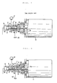
- a sleeve-like element 3 is slidably mounted in a valve bore 2 formed in a valve body 1 of the control valve.
- an inlet port 4 and a drain port 5 are formed in the sleeve-like element 3 in the sleeve-like element 3.
- the sleeve-like element 3 has its front-end interior portion 3a communicate with an outlet port 6 formed in the valve body 1 of the control valve.
- a spool valve 7 is slidably mounted in the sleeve-like element 3.
- spool valve 7 In the spool valve 7 are formed: an axial bore 8; and a radial port 9 which communicates with the axial bore 8 and is formed in a small-diameter portion 7a of the spool valve 7.
- a compression spring 10 is provided to spring bias the spool valve 7 into a position in which: an area defined between the sleeve-like element 3 and the small-diameter portion 7a of the spool valve 7 communicates with the drain port 5; and a moving rod 11a of a solenoid 11, which rod 11a is oppositely disposed from the spool valve 7, abuts on a base-end surface of the spool valve 7.
- the solenoid 11 When an electric current is supplied to the solenoid 11 to energize the same, the solenoid 11 has the moving rod 11a thereof move leftward as viewed in Fig. 1 so that the spool valve 7 is pushed leftward by the moving rod 11a of the solenoid 11 to reach a position in which an area defined between the sleeve-like element 3 and the small-diameter portion 7a of the spool valve 7 communicates with the inlet port 4, whereby the pressure oil supplied from a hydraulic pump P is supplied to the outlet port 6 through: the inlet port 4; the area defined between the sleeve-like element 3 and the small-diameter portion 7a of the spool valve 7; radial port 9; axial bore 8; and the front-end interior portion 3a of the sleeve-like element 3.
- the control valve having the above construction is well known.
- the spool valve 5 moves into a position in which: the area defined between the sleeve-like element 3 and the small-diameter portion 7a of the spool valve 7 communicates with the drain port 5; and the outlet port 6 communicates with a reservoir 12, so that no pressure exists in the outlet port 6.
- air exists in an outlet-side passage of a hydraulic circuit of the control valve, such air is compressed when the solenoid 11 is energized to press its moving rod 11a against the spool valve 7 so as to have a pressure of the pressure oil in the outlet port build up to a predetermined level. consequently, such compression of air considerably impairs the control valve in responsibility.
- the spool valve 7 takes too much time until the area defined between the sleeve-like element 3 and the small-diameter portion 7a of the spool valve 7 reaches a position in which the area communicates with the inlet port 4, and, therefore, in this respect, the conventional control valve is further impaired in responsibility.
- the present invention was made. Consequently, it is an object of the present invention to provide an electrohydraulic proportional control valve which is improved in responsibility: by always pressurizing a pressure oil supplied to an outlet-side passage of a hydraulic circuit of the control valve to prevent air from entering the outlet-side passage; and by moving a spool valve of the control valve without causing any time delay when a solenoid of the control valve is energized.
- An electrohydraulic proportional control valve comprising in combination: a spool valve for permitting/preventing communication between: an inlet port communicating with a hydraulic pump disposed in a hydraulic circuit of the control valve; and an outlet port communicating with an outlet-side passage of the hydraulic circuit; a spring means for applying a spring force to a base-end surface of the spool valve so as to have the spring force balance a hydraulic force applied to a front-end surface of the spool valve so that the spool valve is held at a position in which the inlet port slightly communicates with the outlet port; and a solenoid provided with a moving rod oppositely disposed from the base-end surface of the spool valve, the solenoid being so energized as to move the spool valve into a position in which the inlet port completely communicates with the outlet port.
- the moving rod of the solenoid loses its pressing force against the spool valve to permit the spool valve to move, under the influence of a spring force exerted by the spring means, into a spring-force/hydraulic-force balanced position in which the inlet port slightly communicates with the outlet port and be held at the position, so that: air is prevented from entering the outlet-side passage of the hydraulic circuit of the control valve; and the spool valve of the control valve is operated without causing any time delay whenever the solenoid of the control valve is energized, whereby the control valve of the present invention is improved in responsibility.
- a spring shoe 20 is provided in the base-end side of the spool valve 7 so that: a first spring 21 is interposed between the spring shoe 20 and a flange portion 7b of the spool valve 7; and a second spring 22 is interposed between the spring shoe 20 and the sleeve-like element 3, whereby the spring shoe 20 abuts on a stopper 23.
- the spool valve 7 is constantly biased leftward as viewed in Fig. 2 by the first spring 21 to move into a position in which the inlet port 4 slightly communicates with the area defined between the sleeve-like element 3 and the small-diameter portion 7a of the spool valve 7.
- the moving rod 11a of the solenoid 11 separates from the spring shoe 20.
- the first spring 21 is set so that the spring force exerted by the first spring 21 to act on the base-end surface of the spool valve 7 balances the hydraulic force acting on the front-end surface of the spool valve 7 at a position in which the inlet port 4 slightly communicates with the outlet port 6 when no electric current is supplied to the solenoid 11 of the control valve.
- the pressure of the pressure oil supplied to the outlet-side passage of the hydraulic circuit of the control valve has a value P o .
- the spring shoe 20 is pushed by the moving rod 11a of the solenoid 11.
- the spring shoe 20 abuts on the base-end surface of the spool valve 7, and pushes the spool valve 7 leftward as viewed in Fig.
Landscapes
- Engineering & Computer Science (AREA)
- General Engineering & Computer Science (AREA)
- Mechanical Engineering (AREA)
- Magnetically Actuated Valves (AREA)
Applications Claiming Priority (2)
| Application Number | Priority Date | Filing Date | Title |
|---|---|---|---|
| JP1988167793U JPH0724711Y2 (ja) | 1988-12-27 | 1988-12-27 | 電気式油圧比例制御弁 |
| JP167793/88U | 1988-12-27 |
Publications (2)
| Publication Number | Publication Date |
|---|---|
| EP0451272A1 true EP0451272A1 (de) | 1991-10-16 |
| EP0451272A4 EP0451272A4 (en) | 1992-10-28 |
Family
ID=15856212
Family Applications (1)
| Application Number | Title | Priority Date | Filing Date |
|---|---|---|---|
| EP19900901020 Withdrawn EP0451272A4 (en) | 1988-12-27 | 1989-12-27 | Electrohydraulic proportional control valve |
Country Status (5)
| Country | Link |
|---|---|
| US (1) | US5163477A (de) |
| EP (1) | EP0451272A4 (de) |
| JP (1) | JPH0724711Y2 (de) |
| KR (1) | KR910700426A (de) |
| WO (1) | WO1990007669A1 (de) |
Cited By (3)
| Publication number | Priority date | Publication date | Assignee | Title |
|---|---|---|---|---|
| EP0676548A1 (de) * | 1994-03-11 | 1995-10-11 | Voac Hydraulics Boras Ab | Einbauventil |
| DE102011055281B3 (de) * | 2011-11-11 | 2013-02-21 | Pierburg Gmbh | Ventilvorrichtung für einen Hydraulikkreislauf sowie Ölpumpenregelanordnung |
| DE102012110742A1 (de) | 2012-11-09 | 2014-05-15 | Pierburg Gmbh | Strömungsgehäuse für ein Ölventil |
Families Citing this family (10)
| Publication number | Priority date | Publication date | Assignee | Title |
|---|---|---|---|---|
| US5458406A (en) * | 1994-01-14 | 1995-10-17 | Itt Corporation | Electronic pressure relief system for traction control |
| US5540558A (en) * | 1995-08-07 | 1996-07-30 | Ingersoll-Rand Company | Apparatus and method for electronically controlling inlet flow and preventing backflow in a compressor |
| DE19535945A1 (de) * | 1995-09-27 | 1997-04-03 | Hydraulik Ring Gmbh | Magnetventil sowie Verfahren zu dessen Herstellung |
| DE19735647C1 (de) * | 1997-08-16 | 1999-02-25 | Trw Fahrwerksyst Gmbh & Co | Verfahren zum Steuern des Lenkvolumenstromes einer hydraulischen Servolenkeinrichtung für Kraftfahrzeuge |
| US6220277B1 (en) * | 1997-10-07 | 2001-04-24 | Roy W. Blain | Flow metering solenoid valve |
| US6609538B2 (en) * | 2001-10-11 | 2003-08-26 | Mico, Inc. | Auto-relieving pressure modulating valve |
| US7353927B2 (en) * | 2005-09-28 | 2008-04-08 | Dana Automotive Systems Group, Llc. | Electro-magnetic actuator for torque coupling with variable pressure-control spool valve |
| JP6462633B2 (ja) * | 2016-06-06 | 2019-01-30 | アイシン精機株式会社 | 電磁弁およびオイルポンプ |
| DE102017131037A1 (de) * | 2016-12-23 | 2018-06-28 | Svm Schultz Verwaltungs-Gmbh & Co. Kg | Schieberventil mit Kanal |
| CN111486147B (zh) * | 2020-06-03 | 2024-04-26 | 江苏科迈液压控制系统有限公司 | 一种负载敏感比例多路阀 |
Family Cites Families (8)
| Publication number | Priority date | Publication date | Assignee | Title |
|---|---|---|---|---|
| US3556155A (en) * | 1969-01-24 | 1971-01-19 | Caterpillar Tractor Co | Variable flow-modulated valve |
| FR2452647A1 (fr) * | 1979-03-26 | 1980-10-24 | Renault | Servo-valve |
| DE3307554C2 (de) * | 1983-03-03 | 1985-09-26 | Mannesmann Rexroth GmbH, 8770 Lohr | Elektrisch regelbares Druckreduzierventil |
| DE8322570U1 (de) * | 1983-08-05 | 1985-01-17 | Robert Bosch Gmbh, 7000 Stuttgart | Druckregler |
| JPS60160414A (ja) * | 1984-02-01 | 1985-08-22 | Hitachi Ltd | 閉ル−プ式油圧制御装置 |
| US4635683A (en) * | 1985-10-03 | 1987-01-13 | Ford Motor Company | Variable force solenoid |
| DE3633312A1 (de) * | 1986-09-30 | 1988-04-07 | Rexroth Mannesmann Gmbh | Magnetbetaetigtes ventil, insbesondere als sicherheitsventil |
| JPH0740784Y2 (ja) * | 1987-04-20 | 1995-09-20 | エヌオーケー株式会社 | 圧力制御用バルブ |
-
1988
- 1988-12-27 JP JP1988167793U patent/JPH0724711Y2/ja not_active Expired - Lifetime
-
1989
- 1989-12-27 KR KR1019900701846A patent/KR910700426A/ko not_active Ceased
- 1989-12-27 EP EP19900901020 patent/EP0451272A4/en not_active Withdrawn
- 1989-12-27 US US07/720,509 patent/US5163477A/en not_active Expired - Fee Related
- 1989-12-27 WO PCT/JP1989/001315 patent/WO1990007669A1/ja not_active Ceased
Cited By (6)
| Publication number | Priority date | Publication date | Assignee | Title |
|---|---|---|---|---|
| EP0676548A1 (de) * | 1994-03-11 | 1995-10-11 | Voac Hydraulics Boras Ab | Einbauventil |
| US5651387A (en) * | 1994-03-11 | 1997-07-29 | Voac Hydraulics Boras Ab | Valve cartridge |
| DE102011055281B3 (de) * | 2011-11-11 | 2013-02-21 | Pierburg Gmbh | Ventilvorrichtung für einen Hydraulikkreislauf sowie Ölpumpenregelanordnung |
| WO2013068142A1 (de) | 2011-11-11 | 2013-05-16 | Pierburg Gmbh | Ventilvorrichtung für einen hydraulikkreislauf sowie ölpumpenregelanordnung |
| US9334978B2 (en) | 2011-11-11 | 2016-05-10 | Pierburg Gmbh | Valve device for a hydraulic circuit, and oil-pump regulating arrangement |
| DE102012110742A1 (de) | 2012-11-09 | 2014-05-15 | Pierburg Gmbh | Strömungsgehäuse für ein Ölventil |
Also Published As
| Publication number | Publication date |
|---|---|
| EP0451272A4 (en) | 1992-10-28 |
| JPH0724711Y2 (ja) | 1995-06-05 |
| WO1990007669A1 (fr) | 1990-07-12 |
| US5163477A (en) | 1992-11-17 |
| KR910700426A (ko) | 1991-03-15 |
| JPH0288077U (de) | 1990-07-12 |
Similar Documents
| Publication | Publication Date | Title |
|---|---|---|
| EP0451272A1 (de) | Elektrohydraulisches proportionales steuerungsventil | |
| US4667476A (en) | Booster | |
| CA1188960A (en) | Relief valve arrangement | |
| EP0761966B1 (de) | Fördermengenregelung für eine Verdrängerpumpe | |
| JPH01229106A (ja) | 制御弁 | |
| US4768841A (en) | Brake control device | |
| EP0439621A4 (en) | Pressure oil feed circuit device for hydraulic cylinder of operation machine | |
| US5226800A (en) | Displacement controlling circuit system for variable displacement pump | |
| EP0796999A3 (de) | Verstellbare Pumpe sowie Fernsteuersystem dafür | |
| US4656923A (en) | Loss stroke reducing apparatus for hydraulic servomechanism | |
| JPH0314081B2 (de) | ||
| EP0984214A4 (de) | Proportionales drucksteuerventil | |
| US5046310A (en) | Load-independent control device for hydraulic load devices | |
| US5052896A (en) | Regulating valve for a hydraulically adjustable control pump | |
| EP0024826A1 (de) | Regelsystem für das Eingangsdrehmoment einer Pumpe mit veränderlicher Fördermenge | |
| US5022716A (en) | Brake system | |
| US5735311A (en) | Pressure compensation valve | |
| US5588463A (en) | Module for controlling pressure in a hydraulic circuit | |
| JP2721528B2 (ja) | アンチスキッドブレーキ制御装置におけるサンプ装置 | |
| US4543791A (en) | Power brake unit | |
| US4250795A (en) | Pressure limiter for hydraulic brake booster | |
| US4850390A (en) | Servo device for controlling the flow rate of a hydraulic system, in particular the power-assisted steering of a vehicle | |
| JP2628665B2 (ja) | 圧力制御弁 | |
| US4466458A (en) | Control valve | |
| JPH1095331A (ja) | 液圧制御弁 |
Legal Events
| Date | Code | Title | Description |
|---|---|---|---|
| PUAI | Public reference made under article 153(3) epc to a published international application that has entered the european phase |
Free format text: ORIGINAL CODE: 0009012 |
|
| 17P | Request for examination filed |
Effective date: 19910619 |
|
| AK | Designated contracting states |
Kind code of ref document: A1 Designated state(s): DE FR GB IT |
|
| A4 | Supplementary search report drawn up and despatched |
Effective date: 19920910 |
|
| AK | Designated contracting states |
Kind code of ref document: A4 Designated state(s): DE FR GB IT |
|
| 17Q | First examination report despatched |
Effective date: 19940429 |
|
| STAA | Information on the status of an ep patent application or granted ep patent |
Free format text: STATUS: THE APPLICATION IS DEEMED TO BE WITHDRAWN |
|
| 18D | Application deemed to be withdrawn |
Effective date: 19950701 |