EP0676548A1 - Einbauventil - Google Patents
Einbauventil Download PDFInfo
- Publication number
- EP0676548A1 EP0676548A1 EP95850050A EP95850050A EP0676548A1 EP 0676548 A1 EP0676548 A1 EP 0676548A1 EP 95850050 A EP95850050 A EP 95850050A EP 95850050 A EP95850050 A EP 95850050A EP 0676548 A1 EP0676548 A1 EP 0676548A1
- Authority
- EP
- European Patent Office
- Prior art keywords
- valve
- pilot
- opening
- barrel
- flow restricting
- Prior art date
- Legal status (The legal status is an assumption and is not a legal conclusion. Google has not performed a legal analysis and makes no representation as to the accuracy of the status listed.)
- Granted
Links
- 239000012530 fluid Substances 0.000 claims abstract description 10
- 239000002184 metal Substances 0.000 claims description 2
- 230000003213 activating effect Effects 0.000 description 1
- 230000003247 decreasing effect Effects 0.000 description 1
- 238000006073 displacement reaction Methods 0.000 description 1
- 238000007373 indentation Methods 0.000 description 1
Images

Classifications
-
- F—MECHANICAL ENGINEERING; LIGHTING; HEATING; WEAPONS; BLASTING
- F16—ENGINEERING ELEMENTS AND UNITS; GENERAL MEASURES FOR PRODUCING AND MAINTAINING EFFECTIVE FUNCTIONING OF MACHINES OR INSTALLATIONS; THERMAL INSULATION IN GENERAL
- F16K—VALVES; TAPS; COCKS; ACTUATING-FLOATS; DEVICES FOR VENTING OR AERATING
- F16K31/00—Actuating devices; Operating means; Releasing devices
- F16K31/02—Actuating devices; Operating means; Releasing devices electric; magnetic
- F16K31/06—Actuating devices; Operating means; Releasing devices electric; magnetic using a magnet, e.g. diaphragm valves, cutting off by means of a liquid
- F16K31/0603—Multiple-way valves
- F16K31/061—Sliding valves
- F16K31/0613—Sliding valves with cylindrical slides
-
- F—MECHANICAL ENGINEERING; LIGHTING; HEATING; WEAPONS; BLASTING
- F15—FLUID-PRESSURE ACTUATORS; HYDRAULICS OR PNEUMATICS IN GENERAL
- F15B—SYSTEMS ACTING BY MEANS OF FLUIDS IN GENERAL; FLUID-PRESSURE ACTUATORS, e.g. SERVOMOTORS; DETAILS OF FLUID-PRESSURE SYSTEMS, NOT OTHERWISE PROVIDED FOR
- F15B13/00—Details of servomotor systems ; Valves for servomotor systems
- F15B13/02—Fluid distribution or supply devices characterised by their adaptation to the control of servomotors
- F15B13/04—Fluid distribution or supply devices characterised by their adaptation to the control of servomotors for use with a single servomotor
- F15B13/042—Fluid distribution or supply devices characterised by their adaptation to the control of servomotors for use with a single servomotor operated by fluid pressure
- F15B13/043—Fluid distribution or supply devices characterised by their adaptation to the control of servomotors for use with a single servomotor operated by fluid pressure with electrically-controlled pilot valves
-
- F—MECHANICAL ENGINEERING; LIGHTING; HEATING; WEAPONS; BLASTING
- F16—ENGINEERING ELEMENTS AND UNITS; GENERAL MEASURES FOR PRODUCING AND MAINTAINING EFFECTIVE FUNCTIONING OF MACHINES OR INSTALLATIONS; THERMAL INSULATION IN GENERAL
- F16K—VALVES; TAPS; COCKS; ACTUATING-FLOATS; DEVICES FOR VENTING OR AERATING
- F16K27/00—Construction of housing; Use of materials therefor
- F16K27/04—Construction of housing; Use of materials therefor of sliding valves
- F16K27/041—Construction of housing; Use of materials therefor of sliding valves cylindrical slide valves
-
- Y—GENERAL TAGGING OF NEW TECHNOLOGICAL DEVELOPMENTS; GENERAL TAGGING OF CROSS-SECTIONAL TECHNOLOGIES SPANNING OVER SEVERAL SECTIONS OF THE IPC; TECHNICAL SUBJECTS COVERED BY FORMER USPC CROSS-REFERENCE ART COLLECTIONS [XRACs] AND DIGESTS
- Y10—TECHNICAL SUBJECTS COVERED BY FORMER USPC
- Y10T—TECHNICAL SUBJECTS COVERED BY FORMER US CLASSIFICATION
- Y10T137/00—Fluid handling
- Y10T137/5109—Convertible
-
- Y—GENERAL TAGGING OF NEW TECHNOLOGICAL DEVELOPMENTS; GENERAL TAGGING OF CROSS-SECTIONAL TECHNOLOGIES SPANNING OVER SEVERAL SECTIONS OF THE IPC; TECHNICAL SUBJECTS COVERED BY FORMER USPC CROSS-REFERENCE ART COLLECTIONS [XRACs] AND DIGESTS
- Y10—TECHNICAL SUBJECTS COVERED BY FORMER USPC
- Y10T—TECHNICAL SUBJECTS COVERED BY FORMER US CLASSIFICATION
- Y10T137/00—Fluid handling
- Y10T137/7504—Removable valve head and seat unit
-
- Y—GENERAL TAGGING OF NEW TECHNOLOGICAL DEVELOPMENTS; GENERAL TAGGING OF CROSS-SECTIONAL TECHNOLOGIES SPANNING OVER SEVERAL SECTIONS OF THE IPC; TECHNICAL SUBJECTS COVERED BY FORMER USPC CROSS-REFERENCE ART COLLECTIONS [XRACs] AND DIGESTS
- Y10—TECHNICAL SUBJECTS COVERED BY FORMER USPC
- Y10T—TECHNICAL SUBJECTS COVERED BY FORMER US CLASSIFICATION
- Y10T137/00—Fluid handling
- Y10T137/8593—Systems
- Y10T137/86493—Multi-way valve unit
- Y10T137/86574—Supply and exhaust
- Y10T137/86582—Pilot-actuated
- Y10T137/86614—Electric
-
- Y—GENERAL TAGGING OF NEW TECHNOLOGICAL DEVELOPMENTS; GENERAL TAGGING OF CROSS-SECTIONAL TECHNOLOGIES SPANNING OVER SEVERAL SECTIONS OF THE IPC; TECHNICAL SUBJECTS COVERED BY FORMER USPC CROSS-REFERENCE ART COLLECTIONS [XRACs] AND DIGESTS
- Y10—TECHNICAL SUBJECTS COVERED BY FORMER USPC
- Y10T—TECHNICAL SUBJECTS COVERED BY FORMER US CLASSIFICATION
- Y10T137/00—Fluid handling
- Y10T137/8593—Systems
- Y10T137/86493—Multi-way valve unit
- Y10T137/86574—Supply and exhaust
- Y10T137/86622—Motor-operated
Definitions
- This invention relates to an electromagnetic pilot valve cartridge for direct mounting on a pilot pressure activated directional valve.
- the invention concerns an electromagnetic pilot valve cartridge of the type comprising a valve barrel for interconnection with a socket portion in the directional valve housing, wherein the valve barrel has laterally disposed fluid communication openings for connection to a pressure fluid passage and a drain passage, respectively, in the directional valve housing, a pilot flow opening disposed at the end of the valve barrel and separated from said laterally disposed openings by a seal ring, and a flow restricting means associated with the pilot flow opening.
- the object of the invention is to accomplish an improved valve cartridge of the above described type as far as compactness and simplicity in design and assemblage are concerned.
- Previous valve cartridges of the above type are disadvantageous mainly in that they have a long and space demanding valve barrel for introduction in a socket portion in the directional valve housing.
- the pilot flow restricting means comprises a nozzle like plug threaded into the end portion of the pilot valve bore. Accordingly, this plug type flow restricting means requires that the valve barrel is extended beyond the length needed just for the axial shifting movement of the pilot valve element.
- Fig 1 shows., partly in section, two identical pilot valve cartridges according to the invention mounted on a directional valve.
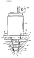
- Fig 2 shows a side view of a pilot valve cartridge according to the invention.
- Fig 3 shows, on a larger scale and partly in section, the end portion of the valve barrel.
- the valve arrangement shown in Fig 1 comprises two identical pilot valve cartridges 10a, 10b mounted on the housing 12 of a pilot pressure activated directional valve 13.
- the latter is intended to control the operation of a hydraulic motor and is connected to a hydraulic pressure pump and to a tank via a drain passage.
- the hydraulic motor drive system including the directional valve, belongs to a common and well known art and, therefore, it has been excluded from this detailed description.
- each of the two pilot valve cartridges 10a, 10b comprises an upper part 15 including an electromagnetic actuator, and a lower valve barrel 16.
- the actuator part 15 is formed with a radial mounting flange 17 by which the cartridge is secured to the directional valve housing 12 by screws 18.
- connection block 20 for electrical wires (not shown) by which an activating current is supplied to the electromagnetic actuator.
- valve barrel 16 which is arranged to be received in a socket portion 21 in the directional valve housing 12 comprises an axial valve bore 22 (see Fig 3) in which is axially displaceable a valve element (not shown) coupled to the electromagnetic actuator.
- a valve bore 22 in which is axially displaceable a valve element (not shown) coupled to the electromagnetic actuator.
- valve barrel 16 is provided with a first lateral fluid communication opening 24 located at the same level as a drain passage 25 in the directional valve housing 12.
- the opening 24 and the drain passage 25 are sealed off by two axially spaced seal rings 26, 27. The latters are disposed between the valve barrel 16 and the socket portion 21.
- valve barrel 16 On a lower level, the valve barrel 16 is provided with a second lateral fluid communication opening 29 communicating with a pump connected pressure fluid passage 30 in the directional valve housing 12.
- valve bore 22 is open to form a pilot flow communication opening.
- the latter is connected to either one of the pilot pressure actuators at the ends of the directional valve 13 via pilot flow passages 31 in the directional valve housing 12.
- a pilot flow restricting cap 32 of substantially cylindrical shape is mounted on the end portion of the valve barrel 16.
- This end cap 32 is formed of pressed sheet metal and comprises a flat circular end wall 33 with a central flow restricting opening 38 and a radial circumferential flange 34.
- the cap 32 is also formed with a number of indentations or internal protrusions 35 for engaging a circumferential groove 36 on the valve barrel 16 and, thereby, retaining the cap 32 on the latter.
- a conical chamfering 37 at the extreme end of the valve barrel 16 facilitates entering of the cap 32 on the valve barrel 16 as the cap 32 is mounted on the latter by pressing.
- a seal ring 40 is supported on the valve barrel 16 to seal off the pilot flow opening 38 from the other openings and passages, chiefly the pump pressure passage 30.
- the seal ring 40 is axially supported by the flange 34 of the cap 32.
- each one of the pilot valve cartridges is arranged to act proportionally to an electrical control signal to supply or drain hydraulic fluid from one of the pilot pressure actuators of the directional valve.
- the pilot flow passage 31 is alternatively connected to the pump pressure passage 30 and the drain passage 25. So, by alternatively pressurizing or depressurizing the pilot pressure actuators of the directional valve 13, the latter is made to control the operation of the hydraulic motor connected thereto.
- the flow restricting cap 32 is one of a set of interchangeable caps, all with flow restricting openings of different sizes, and changing degree of flow restriction is easily done by exchanging the cap actually fitted on the valve barrel for another cap with larger or smaller restriction opening 38.
- this new arrangement makes it possible to substantially reduce the length of the valve barrel 16.
- this new cup-shaped pilot flow restrictor cap is located entirely outside the valve bore 22 and has a thin end wall 33 only which adds very little to the length of the valve barrel 16.
- the valve bore 22, as well as the valve barrel 16 itself does not need to be any longer than what is needed for the shifting of the pilot valve element.
- the valve barrel 16 as well as the pilot valve cartridge as a whole may be given a very compact design. Also the space required in the directional valve housing 12 for the valve barrel receiving socket portions 21 is decreased, which results in a more compact overall design.
Landscapes
- Engineering & Computer Science (AREA)
- General Engineering & Computer Science (AREA)
- Mechanical Engineering (AREA)
- Physics & Mathematics (AREA)
- Fluid Mechanics (AREA)
- Valve Housings (AREA)
- Quick-Acting Or Multi-Walled Pipe Joints (AREA)
- Magnetically Actuated Valves (AREA)
Applications Claiming Priority (2)
| Application Number | Priority Date | Filing Date | Title |
|---|---|---|---|
| SE9400835 | 1994-03-11 | ||
| SE9400835A SE507067C2 (sv) | 1994-03-11 | 1994-03-11 | Elektromagnetisk pilotventilinsats med utbytbar flödesstrypande ändförslutning |
Publications (2)
| Publication Number | Publication Date |
|---|---|
| EP0676548A1 true EP0676548A1 (de) | 1995-10-11 |
| EP0676548B1 EP0676548B1 (de) | 1999-06-02 |
Family
ID=20393255
Family Applications (1)
| Application Number | Title | Priority Date | Filing Date |
|---|---|---|---|
| EP95850050A Expired - Lifetime EP0676548B1 (de) | 1994-03-11 | 1995-03-09 | Einbauventil |
Country Status (4)
| Country | Link |
|---|---|
| US (1) | US5651387A (de) |
| EP (1) | EP0676548B1 (de) |
| DE (1) | DE69509967T2 (de) |
| SE (1) | SE507067C2 (de) |
Cited By (7)
| Publication number | Priority date | Publication date | Assignee | Title |
|---|---|---|---|---|
| WO1999002866A1 (de) * | 1997-07-12 | 1999-01-21 | Mannesmann Rexroth Ag | Hydraulisches einbauventil, insbesondere für eine hydraulische nockenwellenverstellung an einem kraftfahrzeugmotor |
| EP0952356A1 (de) * | 1998-04-20 | 1999-10-27 | HEILMEIER & WEINLEIN Fabrik für Oel-Hydraulik GmbH & Co. KG | Einschraubventil und Einschraubventil-Anordnung |
| EP0939870A4 (de) * | 1996-09-04 | 2000-09-20 | Taprite Fassco Manufacturing C | Modularer regler |
| EP1055852A3 (de) * | 1999-05-28 | 2002-09-18 | Lindauer Dornier Gesellschaft M.B.H | Magnetventil |
| EP1582794A3 (de) * | 2004-03-29 | 2005-12-21 | Aisin Seiki Kabushiki Kaisha | Elektromagnetischer Aktor |
| EP1717497A1 (de) * | 2005-04-28 | 2006-11-02 | G. Kromschröder Aktiengesellschaft | Gasarmatur |
| WO2008098585A1 (de) * | 2007-02-13 | 2008-08-21 | Daimler Ag | Elektromagnetisches ventil für ein brennstoffzellensystem |
Families Citing this family (6)
| Publication number | Priority date | Publication date | Assignee | Title |
|---|---|---|---|---|
| US5992450A (en) * | 1998-06-30 | 1999-11-30 | Eaton Corporation | Cartridge valve having solenoid bypass and integral relief valve |
| DE19842334C1 (de) * | 1998-09-16 | 1999-12-16 | Bosch Gmbh Robert | Magnetventil, insbesondere für die Verwendung in einem Modul für eine elektrohydraulische Getriebesteuerung |
| JP2000257552A (ja) * | 1999-03-04 | 2000-09-19 | Toyota Autom Loom Works Ltd | 可変容量圧縮機における制御弁の取付構造 |
| US6539971B2 (en) * | 2001-08-17 | 2003-04-01 | Eaton Corporation | Method and apparatus for mounting solenoid operated valve |
| DE10308074A1 (de) * | 2003-02-26 | 2004-09-09 | Hydraulik-Ring Gmbh | Ventil, vorzugsweise Proportionalmagnetventil |
| US9382905B2 (en) * | 2013-09-09 | 2016-07-05 | Federal Signal Corporation | High power reciprocating pump manifold and valve cartridges |
Citations (5)
| Publication number | Priority date | Publication date | Assignee | Title |
|---|---|---|---|---|
| EP0073268A1 (de) * | 1981-09-02 | 1983-03-09 | Vickers Systems GmbH | Elektrohydraulische Regelung eines Stellkolbens |
| DE3633312A1 (de) * | 1986-09-30 | 1988-04-07 | Rexroth Mannesmann Gmbh | Magnetbetaetigtes ventil, insbesondere als sicherheitsventil |
| EP0385286A2 (de) * | 1989-02-28 | 1990-09-05 | Lectron Products, Inc. | Mittels eines eine veränderliche Kraft erzeugenden Elektromagneten arbeitender Druckregler für die elektronische Steuerung eines Getriebes |
| EP0451272A1 (de) * | 1988-12-27 | 1991-10-16 | Kabushiki Kaisha Komatsu Seisakusho | Elektrohydraulisches proportionales steuerungsventil |
| US5156184A (en) * | 1991-10-21 | 1992-10-20 | Sterling Hydraulics, Inc. | Solenoid operated transmission cartridge valve |
Family Cites Families (3)
| Publication number | Priority date | Publication date | Assignee | Title |
|---|---|---|---|---|
| US3736958A (en) * | 1972-04-13 | 1973-06-05 | Lockheed Aircraft Corp | Four-way solenoid selector valve |
| DE3307554C2 (de) * | 1983-03-03 | 1985-09-26 | Mannesmann Rexroth GmbH, 8770 Lohr | Elektrisch regelbares Druckreduzierventil |
| US4947893A (en) * | 1989-02-28 | 1990-08-14 | Lectron Products, Inc. | Variable force solenoid pressure regulator for electronic transmission controller |
-
1994
- 1994-03-11 SE SE9400835A patent/SE507067C2/sv not_active IP Right Cessation
-
1995
- 1995-03-09 EP EP95850050A patent/EP0676548B1/de not_active Expired - Lifetime
- 1995-03-09 DE DE69509967T patent/DE69509967T2/de not_active Expired - Fee Related
- 1995-03-13 US US08/402,955 patent/US5651387A/en not_active Expired - Lifetime
Patent Citations (5)
| Publication number | Priority date | Publication date | Assignee | Title |
|---|---|---|---|---|
| EP0073268A1 (de) * | 1981-09-02 | 1983-03-09 | Vickers Systems GmbH | Elektrohydraulische Regelung eines Stellkolbens |
| DE3633312A1 (de) * | 1986-09-30 | 1988-04-07 | Rexroth Mannesmann Gmbh | Magnetbetaetigtes ventil, insbesondere als sicherheitsventil |
| EP0451272A1 (de) * | 1988-12-27 | 1991-10-16 | Kabushiki Kaisha Komatsu Seisakusho | Elektrohydraulisches proportionales steuerungsventil |
| EP0385286A2 (de) * | 1989-02-28 | 1990-09-05 | Lectron Products, Inc. | Mittels eines eine veränderliche Kraft erzeugenden Elektromagneten arbeitender Druckregler für die elektronische Steuerung eines Getriebes |
| US5156184A (en) * | 1991-10-21 | 1992-10-20 | Sterling Hydraulics, Inc. | Solenoid operated transmission cartridge valve |
Cited By (9)
| Publication number | Priority date | Publication date | Assignee | Title |
|---|---|---|---|---|
| EP0939870A4 (de) * | 1996-09-04 | 2000-09-20 | Taprite Fassco Manufacturing C | Modularer regler |
| WO1999002866A1 (de) * | 1997-07-12 | 1999-01-21 | Mannesmann Rexroth Ag | Hydraulisches einbauventil, insbesondere für eine hydraulische nockenwellenverstellung an einem kraftfahrzeugmotor |
| EP0952356A1 (de) * | 1998-04-20 | 1999-10-27 | HEILMEIER & WEINLEIN Fabrik für Oel-Hydraulik GmbH & Co. KG | Einschraubventil und Einschraubventil-Anordnung |
| US6192921B1 (en) | 1998-04-20 | 2001-02-27 | Heilmeier & Weinlein Fabrik Fur Oel-Hydraulik Gmbh & Co. | Screw-in cartridge valve and screw-in cartridge valve assembly |
| EP1055852A3 (de) * | 1999-05-28 | 2002-09-18 | Lindauer Dornier Gesellschaft M.B.H | Magnetventil |
| EP1582794A3 (de) * | 2004-03-29 | 2005-12-21 | Aisin Seiki Kabushiki Kaisha | Elektromagnetischer Aktor |
| US7207546B2 (en) | 2004-03-29 | 2007-04-24 | Aisin Seiki Kabushiki Kaisha | Electromagnetic actuator |
| EP1717497A1 (de) * | 2005-04-28 | 2006-11-02 | G. Kromschröder Aktiengesellschaft | Gasarmatur |
| WO2008098585A1 (de) * | 2007-02-13 | 2008-08-21 | Daimler Ag | Elektromagnetisches ventil für ein brennstoffzellensystem |
Also Published As
| Publication number | Publication date |
|---|---|
| SE507067C2 (sv) | 1998-03-23 |
| DE69509967D1 (de) | 1999-07-08 |
| SE9400835L (sv) | 1995-09-12 |
| EP0676548B1 (de) | 1999-06-02 |
| SE9400835D0 (sv) | 1994-03-11 |
| DE69509967T2 (de) | 2000-01-13 |
| US5651387A (en) | 1997-07-29 |
Similar Documents
| Publication | Publication Date | Title |
|---|---|---|
| EP0676548B1 (de) | Einbauventil | |
| US6044752A (en) | Hydraulic cylinder unit | |
| US6161585A (en) | High flow proportional pressure reducing valve | |
| US7971599B2 (en) | Air-operated valve | |
| EP0538986B1 (de) | Elektromagnetisches Einsatzventil | |
| US4681514A (en) | Radial piston pump having sealing disc | |
| US6227381B1 (en) | Filter | |
| JP6367432B1 (ja) | 逆止め弁付シーケンス弁 | |
| US4103711A (en) | Fluid logic flip-flop | |
| EP1803980A1 (de) | Ventil mit Hohlkolben | |
| JPH0369026B2 (de) | ||
| EP1670563B1 (de) | Rückspülbarer filter mit schleuderabreinigung | |
| CN111322283A (zh) | 具有阀壳的液压阀系统和制造阀壳的方法 | |
| US4944676A (en) | Replaceable fluid flow control device for dental units | |
| EP1134469B1 (de) | Mehrwegeschieber mit Aufsatzbefestigungselementen | |
| US6988514B2 (en) | Hydroaccumulator, in a particular a bladder accumulator | |
| US4089252A (en) | Proportional force amplifier | |
| US6892759B2 (en) | Valve having at least one screen | |
| EP1070854A3 (de) | Wegeventil | |
| CN113994103B (zh) | 液压控制块和具有该控制块的伺服液压轴 | |
| US6357475B1 (en) | Pneumatic sequential control valve | |
| CN112324950A (zh) | 一种电动球阀 | |
| CN224200886U (zh) | 一种控制阀 | |
| GB2183915A (en) | Hydraulic pressure operated switch | |
| SU1198221A1 (ru) | Распределительное устройство механизированной крепи |
Legal Events
| Date | Code | Title | Description |
|---|---|---|---|
| PUAI | Public reference made under article 153(3) epc to a published international application that has entered the european phase |
Free format text: ORIGINAL CODE: 0009012 |
|
| AK | Designated contracting states |
Kind code of ref document: A1 Designated state(s): DE FR GB |
|
| 17P | Request for examination filed |
Effective date: 19960318 |
|
| GRAG | Despatch of communication of intention to grant |
Free format text: ORIGINAL CODE: EPIDOS AGRA |
|
| 17Q | First examination report despatched |
Effective date: 19980813 |
|
| GRAG | Despatch of communication of intention to grant |
Free format text: ORIGINAL CODE: EPIDOS AGRA |
|
| GRAH | Despatch of communication of intention to grant a patent |
Free format text: ORIGINAL CODE: EPIDOS IGRA |
|
| GRAH | Despatch of communication of intention to grant a patent |
Free format text: ORIGINAL CODE: EPIDOS IGRA |
|
| GRAA | (expected) grant |
Free format text: ORIGINAL CODE: 0009210 |
|
| AK | Designated contracting states |
Kind code of ref document: B1 Designated state(s): DE FR GB |
|
| REF | Corresponds to: |
Ref document number: 69509967 Country of ref document: DE Date of ref document: 19990708 |
|
| ET | Fr: translation filed | ||
| PLBE | No opposition filed within time limit |
Free format text: ORIGINAL CODE: 0009261 |
|
| STAA | Information on the status of an ep patent application or granted ep patent |
Free format text: STATUS: NO OPPOSITION FILED WITHIN TIME LIMIT |
|
| 26N | No opposition filed | ||
| REG | Reference to a national code |
Ref country code: GB Ref legal event code: IF02 |
|
| REG | Reference to a national code |
Ref country code: GB Ref legal event code: 732E |
|
| PGFP | Annual fee paid to national office [announced via postgrant information from national office to epo] |
Ref country code: FR Payment date: 20060228 Year of fee payment: 12 |
|
| PGFP | Annual fee paid to national office [announced via postgrant information from national office to epo] |
Ref country code: GB Payment date: 20060309 Year of fee payment: 12 |
|
| GBPC | Gb: european patent ceased through non-payment of renewal fee |
Effective date: 20070309 |
|
| REG | Reference to a national code |
Ref country code: FR Ref legal event code: ST Effective date: 20071130 |
|
| PG25 | Lapsed in a contracting state [announced via postgrant information from national office to epo] |
Ref country code: GB Free format text: LAPSE BECAUSE OF NON-PAYMENT OF DUE FEES Effective date: 20070309 |
|
| PG25 | Lapsed in a contracting state [announced via postgrant information from national office to epo] |
Ref country code: FR Free format text: LAPSE BECAUSE OF NON-PAYMENT OF DUE FEES Effective date: 20070402 |
|
| PGFP | Annual fee paid to national office [announced via postgrant information from national office to epo] |
Ref country code: DE Payment date: 20090324 Year of fee payment: 15 |
|
| PG25 | Lapsed in a contracting state [announced via postgrant information from national office to epo] |
Ref country code: DE Free format text: LAPSE BECAUSE OF NON-PAYMENT OF DUE FEES Effective date: 20101001 |