EP0451294B1 - Spritzgiessvorrichtung vom kurbeltyp - Google Patents
Spritzgiessvorrichtung vom kurbeltyp Download PDFInfo
- Publication number
- EP0451294B1 EP0451294B1 EP90916055A EP90916055A EP0451294B1 EP 0451294 B1 EP0451294 B1 EP 0451294B1 EP 90916055 A EP90916055 A EP 90916055A EP 90916055 A EP90916055 A EP 90916055A EP 0451294 B1 EP0451294 B1 EP 0451294B1
- Authority
- EP
- European Patent Office
- Prior art keywords
- crank
- driving shaft
- injection
- injection apparatus
- output shaft
- Prior art date
- Legal status (The legal status is an assumption and is not a legal conclusion. Google has not performed a legal analysis and makes no representation as to the accuracy of the status listed.)
- Expired - Lifetime
Links
Images


Classifications
-
- B—PERFORMING OPERATIONS; TRANSPORTING
- B29—WORKING OF PLASTICS; WORKING OF SUBSTANCES IN A PLASTIC STATE IN GENERAL
- B29C—SHAPING OR JOINING OF PLASTICS; SHAPING OF MATERIAL IN A PLASTIC STATE, NOT OTHERWISE PROVIDED FOR; AFTER-TREATMENT OF THE SHAPED PRODUCTS, e.g. REPAIRING
- B29C45/00—Injection moulding, i.e. forcing the required volume of moulding material through a nozzle into a closed mould; Apparatus therefor
- B29C45/17—Component parts, details or accessories; Auxiliary operations
- B29C45/46—Means for plasticising or homogenising the moulding material or forcing it into the mould
- B29C45/47—Means for plasticising or homogenising the moulding material or forcing it into the mould using screws
- B29C45/50—Axially movable screw
- B29C45/5008—Drive means therefor
- B29C2045/502—Drive means therefor screws axially driven by a crank or eccentric mechanism
Definitions
- the present invention relates to a crank type injection apparatus mounted on an injection molding machine.
- An injection molding machine comprises an injecting mechanism for filling molten resin into a mold.
- a hydraulic injection mechanism comprised of a hydraulic cylinder and an injection plunger.
- the hydraulic injection mechanism has such drawbacks that difficulty is encountered in simplifying its structure, a lot of labor is required to carry out maintenance of the hydraulic cylinder and hydraulic fluid paths, and considerable difficulty occurs in precisely controlling the reciprocation of the injection plunger.
- a typical motor-driven injection mechanism includes a ball screw/ball nut mechanism which has a ball screw rotatably supported and coupled to the output shaft of a servomotor, and a ball nut threadedly engaged therewith, the ball nut being supported in a manner unrotatable but movable in unison with an injection screw.
- the rotary motion of the motor output shaft is converted into linear motion of the injection screw through the ball screw/ball nut mechanism, so as to drive the screw toward the direction of injection.
- the motor-driven injection mechanism which requires the expensive ball screw/ball nut mechanism, has such a drawback that it is high-priced.
- the servomotor is operatively coupled to the ball screw through the medium of a power transmission means which comprises toothed pulleys respectively fixed on the motor output shaft and the ball screw, and a timing belt stretched between these pulleys.
- a power transmission means which comprises toothed pulleys respectively fixed on the motor output shaft and the ball screw, and a timing belt stretched between these pulleys.
- JP-A-37-012133 Another type of injection mechanism is disclosed in JP-A-37-012133, wherein a crank mechanism is employed to transfer reciprocal driving force from a rotary drive shaft to an injection screw, without any proposal being provided for how the rotary drive shaft may be driven.
- the object of the present invention is to provide a crank type injection apparatus which may be low-priced and which is capable of driving an injection screw with a desired driving force, without the need of employing a high-type electric motor.
- crank type injection apparatus for use in an injection molding machine which has an injection screw disposed to be movable toward and away from a stationary plate, comprising: a driving shaft rotatably supported; and crank means for converting forward and reverse rotation of said driving shaft into reciprocating motion of the injection screw; characterised by: an electric motor having an output shaft thereof and arranged to rotate said output shaft in forward and reverse directions; a reduction gearing interposed between said driving shaft and the output shaft of said electric motor; and control means adapted to control drive of said electric motor in such a manner that said driving shaft is rotated forwardly and reversely within a predetermined rotary angular region corresponding to a predetermined operational region of said crank means, in which angular region upper and lower dead centers of said crank means and vicinities of said upper and lower dead centers are not contained.
- the crank type injection apparatus of the present invention the rotation of the electric motor is converted into the reciprocating motion of the injection screw, and hence an expensive ball screw/ball nut mechanism is not required.
- This makes it possible to provide a low-priced injection apparatus.
- the reduction gearing is interposed between the electric motor and the driving shaft which is coupled to the crank means for reciprocating the injection screw, the injection screw can be driven with a desired driving force even if the output torque of the electric motor is small.
- a high output type electric motor is not required, and hence the cost of the injection apparatus can be reduced.
- the crank means is operable within the predetermined operational region in which the upper and lower dead centers of the crank means and the vicinities of the dead centers are not contained, the injection speed is not rapidly reduced in initial and final stages of the injection process, and the rate at which the injection pressure changes with rotation of the driving shaft is not suddenly increased.
- a desired injection speed can be obtained over the entire operational region of the crank means, and hence the injection process can be smoothly carried out.
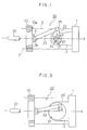
- an injection molding machine on which a crank type injection apparatus according to a first embodiment of the present invention is mounted comprises a rear plate 1 fixed on an extruder base (not shown), a front plate (not shown), and a plurality of tie bars (shown in a chain line) 2 each having opposite ends thereof respectively coupled to these plates.
- the crank type injection apparatus comprises a pusher plate 10 disposed for reciprocal motion along the tie bars 2 between the front plate and the rear plate 1, and a crank mechanism 20 for causing the pusher plate 10 to move toward and away from the rear plate 1.
- the pusher plate 10 is formed at its peripheral portion with a plurality of guide holes 10a, and the tie bars 2 respectively extend through the guide holes 10a and in parallel with one another.
- An injection screw 30 is disposed at a front face of the pusher plate 10 to be movable in unison with the pusher plate, and is fitted in an injection cylinder (not shown) having a tip end thereof provided with an injection nozzle (not shown).
- a first bracket 3 is fixed on the front face of the rear plate 1
- a second bracket 4 is fixed on the rear face of the pusher plate 10, these brackets extending along the axis X of the injection screw 30.
- the crank mechanism 20 comprises a driving shaft 21 which is rotatably supported by the first bracket 3.
- the driving shaft 21 is comprised of first and second shaft portions 21a and 21b (Fig. 2) which are arranged for integral rotation.
- a crank arm 22 fixedly fitted in the driving shaft 21 cooperates with a connecting rod 23 to form crank means for converting the rotary motion of the driving shaft 21 into linear motions of the pusher plate 10 and the injection screw 30.
- the crank arm 22 is fixed on the driving shaft 21 by means of a key 24, and is arranged to rotate in unison with the driving shaft 21.
- the connecting rod 23 has its one end coupled to the outer end of the crank arm 22 via a crank pin 25, to be swingable relative to the crank arm.
- Another end of the connecting rod 23 is coupled to the second bracket 4 via a coupling pin for swing motion relative thereto.
- the driving shaft 21, the crank pin 25 and the coupling pin 26 respectively extend in parallel one another, and in the direction perpendicular to the screw axis X, the driving shaft 21 and the coupling pin 26 being disposed on the screw axis X.
- the crank type injection apparatus further comprises a servomotor 40 fixed on the first bracket 3 via a mounting member 5, a reduction gearing 50 interposed between the output shaft 41 of the servomotor 40 and the driving shaft 21 of the crank mechanism 20, for amplifying the output torque of the servomotor 40, and control means 60 for controlling the drive of the servomotor 40, the reduction gearing 50 being fixed to the first bracket 3.
- the servomotor 40 may be comprised of a general purpose servomotor other than a high output type servomotor.
- the reduction gearing 50 is comprised of a built-in type reduction gearing whose reduction ratio is high, e.g., a RV reduction gearing manufactured by Teijin Seiki Co., Ltd.
- the RV reduction gearing 50 comprises a sun gear 51 disposed for rotation in unison with the motor output shaft 41, and is so designed as to cause each of three planet gears (one of them is denoted by reference numeral 52) meshing with the sun gear 51 to turn around on its own axis, with rotation of the sun gear 51, while moving around the sun gear 51.
- a crank shaft 53 supported by a casing 56 for rotation in unison with the planet gears 52, supports two eccentric gears 54, and cycloid-shaped external teeth formed in each eccentric gear are in mesh with a stationary ring gear 55 (inside tooth).
- the eccentric gears 54 rotates around the crank shaft 53 while moving along with the ring gear 55, and further, the casing 56 by which the crank shaft 53 is rotatably supported and an output shaft 57 arranged for rotation in unison with the casing rotate with a large reduction ratio (1:40 in the present embodiment) with respect to the rotation of the motor output shaft 41.
- the output shaft 57 of the reduction gearing 50 is formed integrally with the shaft portion 21b of the driving shaft 21 of the crank mechanism 20, and is rotatably supported by the first bracket 3 through a ball bearing 61.
- the first shaft portion 21a of the driving shaft 21 is disposed in alignment with the second shaft portion 21b, and is coupled to the second shaft portion for rotation in unison therewith, and is further rotatably supported by the first bracket 3 through a ball bearing 62.
- control means for controlling the drive of the servomotor 40 is mounted on the injection molding machine, and is comprised of a numerical control device including a processor, a servo circuit (not shown), etc.
- the servo circuit is connected to the servomotor 40 and a position detector 42 attached thereto.
- the numerical control device 60 is operable to control starting, stopping, speed of rotation, and direction of rotation of the servomotor 40, and further control the number of rotation (the total rotary angle) of the servomotor 40 in one injection process, in accordance with a control program prepared beforehand.
- the rotation number of the servomotor 40 in one injection process is controlled in such a manner that the driving shaft 21 of the crank mechanism 20 is rotated, from the start of the injection process to the completion thereof, within a predetermined rotary angular region (e.g., the rotary angular region varying from 30° to 150° ) corresponding to a predetermined operational region in which the upper and lower dead centers of the crank mechanism 20 and the vicinities of these dead centers are not contained.
- the number of motor rotation in a metering process is controlled in a similar manner, so that the driving shaft 21 is rotated, e.g., from 150° to 30° .
- the rotary angle of the driving shaft 21 is represented by that angle ⁇ (shown in Fig.
- reference numeral 70 denotes a load cell held between the pusher plate 10 and the second bracket 4, for detecting a reaction force (injection pressure, back pressure) of molten resin acting on the injection screw 30.
- the numerical control device 60 is so designed as to execute injection pressure and back pressure control in accordance with output of the load cell, where required. However, such control is not carried out in this embodiment.
- the processor of the numerical control device 60 starts pulse distribution to the servo circuit after injection start command, direction of rotation and target rotational speed of the servomotor 40, target rotation number of the servomotor 40 over the time period from the start of injection to the completion thereof are read by the processor from the control program, the drive for the forward rotation of the servomotor 40 is started by the servo circuit.
- the forward rotary force of the servomotor 40 is amplified by the reduction gearing 50, and is then transmitted to the driving shaft 21 of the crank mechanism 20.
- the driving shaft 21 is rotated in the forward direction from its initial rotary angular position of 30° with a great driving force and at a predetermined speed.
- the pusher plate 10 and the injection screw 30 arranged integrally therewith are driven in the forward direction with a great driving force, through the key 24, crank arm 22, crank pin 25, connecting rod 23, and coupling pin 26 of the crank mechanism 20 and through the second bracket 4, so that the molten resin within the injection cylinder is injected into a mold.
- the pulse distribution from the processor to the servo circuit is periodically executed, while feedback pulses from the position detector 42 are applied to the servo circuit with rotation of the servomotor 40, and a deviation between the current target rotatinal position of the motor and its actual rotational position is stored in an error resistor of the servo circuit. Thereafter, when a final target rotational position is reached or when the rotary angle of the driving shaft 21 reaches 150° , the rotation of the servomotor 40 is stopped, whereby the injection process is completed. Then, the hold process is entered.
- the driving shaft 21 of the crank mechanism 20 is driven by the servomotor 40 through the reduction gearing 50 so as to rotate forwardly.
- This makes it possible to drive, through the crank mechanism and the pusher plate 10, the injection screw 30 in the forward direction with a desired driving force against the reaction force generated by the molten resin, even if the servomotor is comprised of a general purpose servomotor.
- the driving shaft 21 is rotated within the rotary angular region varying from 30° to 150° , corresponding to the operational region which does not include the upper and lower dead centers of the crank mechanism 20 and the vicinities of the dead centers. As a result, a rapid decrease (shown by the dotted line in Fig.
- Fig. 4 shows the injection speed V and the changing rate ⁇ P of the injection pressure when the driving shaft 21 rotates at a constant speed. If necessary, the number of rotation of the driving shaft can be variably controlled.
- the driving shaft 21 is rotated reversely from the rotary angular position of 150° toward the rotary angular position of 30° by the servomotor 40 under the control of the processor.
- the injection screw 30 and the pusher plate 10 are moved back up to their initial positions, and await the next injection process.
- crank type injection apparatus of the second embodiment of the present invention will be described. Meanwhile, like elements common to the first embodiment are shown by like numerals, and explanations thereof will be omitted.
- the driving shaft 21, the crank arm 22, and the key 24 in the first embodiment are removed, and the connecting rod 23 has one end thereof coupled to the output shaft 57 of the reduction gearing 50 via a crank pin 25'.
- the crank pin 25' which is comprised of two halves 25'a and 25'b coupled to each other for integral rotation, is disposed to be off-centered with respect to the axis of the output shaft 57, and cooperates with the connecting rod 23 and the line to form a crank mechanism 20'.
- the output shaft 57 of the reduction gearing 50 functions as a driving shaft for the crank mechanism 20'.
- the stroke of the pusher plate 10 is the same in both the embodiments.
- the rotary angle of the driving shaft 57 is limited within a region varying from 30° to 150° .
- the rotary angle of the driving shaft is represented by an angle ⁇ formed between a straight line, which connects the center of the crank pin 25' with that of the driving shaft 57, and the screw axis X. This rotary angle assumes a value of 0° , when the crank pin 25' is positioned on the screw axis X at the side close to the rear plate 1.
- the injection apparatus of the second embodiment since the elements 21, 22 and 24 of the first embodiment are unnecessary, the number of components can be reduced so that the crank mechanism 20' is simplified in construction, and its durability can be improved. Because the stroke of the pusher plate 10 is limited to a value smaller than the diameter of the output shaft 57 of the reduction gearing 50, the injection apparatus is suitable to a small-sized injection molding machine.
- the present invention is not limited to the aforementioned first and second embodiments, and various modifications thereof may be made.
- the RV reduction gearing is employed as the reduction gearing 50 in the embodiments, other reduction gearings may be employed.
- a cyclonic reduction gearing manufactured by Sumitomo jukogyo Co., Ltd.
- this gearing is preferable for use as a built-in type reduction gearing with a high reduction ratio.
- the rotary angular region of the driving shafts 21 and 57 is not always limited within a region of 30° to 150° , and the rotary angular region may be determined appropriately in dependence on the specification of the injection molding machine concerned.
- the driving shaft 21 and the crank pin 25' each comprised of two component parts are used respectively in the first and the second embodiments, a driving shaft and a crank pin each comprised of a single part may be also employed.
- the connecting rod 23 is coupled through the crank pin 25' to the output shaft 57 of the reduction gearing 50, serving as the driving shaft.
- the connecting rod may be coupled to a disc fixed to the output shaft of the reduction gearing, whereby the stroke of the pusher plate 10 can be increased.
Landscapes
- Engineering & Computer Science (AREA)
- Manufacturing & Machinery (AREA)
- Mechanical Engineering (AREA)
- Injection Moulding Of Plastics Or The Like (AREA)
Claims (9)
- Spritzgießvorrichtung vom Kurbeltyp zur Benutzung in einer Spritzgießmaschine, die eine Einspritzförderschnecke (30) hat, welche so angeordnet ist, daß sie zu einer ortsfesten Platte (1) hin und von dieser fort bewegbar ist, mit
einer Antriebswelle (21, 57), die drehbar gelagert ist, und
einer Kurbel (22, 23) zum Umsetzen einer Vorwärts- und einer Rückwärtsdrehung der Antriebswelle (21, 57) in eine Hin- u. Herbewegung der Einspritzförderschnecke (30),
gekennzeichnet durch
einen Elektromotor (40), der eine Ausgangswelle (41) hat und so beschaffen ist, daß er die Ausgangswelle (41) in Vorwärts- u. Rückwärtsrichtungen dreht,
ein Untersetzungsgetriebe (50), das zwischen der Antriebswelle (21, 57) und der Ausgangswelle (41) des Elektromotors (40) liegt ist, und
eine Steuereinrichtung (60), die dazu bestimmt ist, den Trieb des Elektromotors (40) in einer Weise zu steuern, daß die Antriebswelle (21, 57) innerhalb eines vorbestimmten Drehwinkelbereichs, der einem vorbestimmten Arbeitsbereich der Kurbel (22, 23) entspricht, vorwärts und rückwärts gedreht wird, in welchem Winkelbereich obere und untere Totpunkte der Kurbel (22, 23) und Umgebungsbereiche der oberen und unteren Totpunkte nicht enthalten sind. - Spritzgießvorrichtung vom Kurbeltyp nach Anspruch 1, bei der die Einspritzvorrichtung in einer Spritzgießmaschine montiert ist, die eine Rückseitenplatte, welche als die ortsfeste Platte (1) dient, und eine Druckplatte (10) hat, die so angeordnet ist, daß sie zusammen mit der Einspritzförderschnecke (30) zu der Rückseitenplatte (1) hin und von dieser fort bewegbar ist, und bei der die Kurbel (22, 23) mit der Druckplatte (10) zum Umsetzen der Vorwärts- u. Rückwärtsdrehung der Antriebswelle (21, 57) in eine Hin- u. Herbewegung der Einspritzförderschnecke durch die Druckplatte (10) verbunden ist.
- Spritzgießvorrichtung vom Kurbeltyp nach Anspruch 2, bei der die Kurbel (22, 23) einen Kurbelarm (22), der mit einem seiner Enden mit der Antriebswelle (21) verbunden ist, eine Verbindungsstange (23), deren eines Ende drehbar mit der Druckplatte (10) verbunden ist, und einen Kurbelzapfen (25) enthält, der ein anderes Ende des Kurbelarms (22) drehbar mit einem anderen Ende der Verbindungsstange (23) verbindet.
- Spritzgießvorrichtung vom Kurbeltyp nach Anspruch 2 oder 3, bei der die Kurbel (22, 23) ferner eine Halterung (4), die an der Druckplatte (10) angebracht ist, und einen Verbindungszapfen (26) enthält, der drehbar das eine Ende der Verbindungsstange (23) mit der Halterung (4) verbindet.
- Spritzgießvorrichtung vom Kurbeltyp nach einem der vorhergehenden Ansprüche, bei der das Untersetzungsgetriebe (50) eine Ausgangswelle (57) hat, die in Ausrichtung mit der Antriebswelle (21) angeordnet und mit der Antriebswelle (21) verbunden ist, und bei der eine Eingangsseite des Untersetzungsgetriebes (50) direkt mit der Ausgangswelle (41) des Elektromotors (40) verbunden ist.
- Spritzgießvorrichtung vom Kurbeltyp nach Anspruch 2 oder Anspruch 4, wenn dieser auf Anspruch 2 rückbezogen ist, bei der die Kurbel einen Kurbelzapfen (25'), der mit der Antriebswelle (57) in einer Weise verbunden ist, daß er in bezug auf eine Achse der Antriebswelle (57) exzentrisch ist, und eine Verbindungsstange (23) enthält, deren Enden drehbar mit dem Kurbelzapfen (25') bzw. der Druckplatte (10) verbunden sind.
- Spritzgießvorrichtung vom Kurbeltyp nach Anspruch 6, bei der das Untersetzungsgetriebe (50) eine Ausgangswelle hat, die als die Antriebswelle (57) dient, und bei der der Kurbelzapfen (25') an der Ausgangswelle (57) des Untersetzungsgetriebes (50) in einer Weise montiert ist, daß er in bezug auf eine Achse der Ausgangswelle des Untersetzungsgetriebes (50) exzentrisch ist.
- Spritzgießvorrichtung vom Kurbeltyp nach einem der vorhergehenden Ansprüche, bei der eine Einspritzgeschwindigkeits-Kennlinie und eine Einspritzdruck-Kennlinie, wovon jede als eine Funktion der Position der Einspritzförderschnecke (30) dargestellt ist, variabel sind.
- Spritzgießvorrichtung vom Kurbeltyp nach einem der vorhergehenden Ansprüche, bei der der vorbestimmte Arbeitsbereich der Kurbel (22, 23) ein Bereich von 30° bis 150° zwischen den oberen und unteren Totpunkten der Kurbel (22, 23) ist.
Applications Claiming Priority (3)
| Application Number | Priority Date | Filing Date | Title |
|---|---|---|---|
| JP1284831A JP2542932B2 (ja) | 1989-11-02 | 1989-11-02 | クランク式射出機構 |
| JP284831/89 | 1989-11-02 | ||
| PCT/JP1990/001408 WO1991006414A1 (en) | 1989-11-02 | 1990-11-01 | Crank type injection device |
Publications (3)
| Publication Number | Publication Date |
|---|---|
| EP0451294A1 EP0451294A1 (de) | 1991-10-16 |
| EP0451294A4 EP0451294A4 (en) | 1991-12-18 |
| EP0451294B1 true EP0451294B1 (de) | 1995-03-22 |
Family
ID=17683576
Family Applications (1)
| Application Number | Title | Priority Date | Filing Date |
|---|---|---|---|
| EP90916055A Expired - Lifetime EP0451294B1 (de) | 1989-11-02 | 1990-11-01 | Spritzgiessvorrichtung vom kurbeltyp |
Country Status (7)
| Country | Link |
|---|---|
| US (1) | US5158783A (de) |
| EP (1) | EP0451294B1 (de) |
| JP (1) | JP2542932B2 (de) |
| KR (1) | KR920700870A (de) |
| CA (1) | CA2044594A1 (de) |
| DE (1) | DE69018063T2 (de) |
| WO (1) | WO1991006414A1 (de) |
Families Citing this family (14)
| Publication number | Priority date | Publication date | Assignee | Title |
|---|---|---|---|---|
| JP2709755B2 (ja) * | 1991-06-28 | 1998-02-04 | ファナック株式会社 | 電動式射出成形機における位置決め補正方法及び補正装置 |
| DE4327710C1 (de) * | 1993-08-18 | 1994-09-08 | Kloeckner Ferromatik Desma | Einspritzaggregat |
| AT2062U1 (de) * | 1997-04-09 | 1998-04-27 | Engel Gmbh Maschbau | Einspritzaggregat für spritzgiessmaschinen |
| JP3453043B2 (ja) * | 1997-04-30 | 2003-10-06 | 東芝機械株式会社 | 旋回機構の数値制御装置 |
| DE19819759C2 (de) * | 1998-05-04 | 2001-09-27 | Battenfeld Gmbh | Vorrichtung zur Betätigung eines Einspritzelements |
| EP1280647B1 (de) * | 2000-05-08 | 2006-09-06 | ProControl AG | Spritzgiessmaschine mit exzenterantrieb |
| DE10051101B4 (de) * | 2000-05-24 | 2007-10-18 | Netstal-Maschinen Ag | Einspritzschneckenantrieb für eine Kunststoffspritzgiessmaschine |
| JP5063081B2 (ja) * | 2006-11-02 | 2012-10-31 | 東洋機械金属株式会社 | ダイカストマシン |
| JP2008188627A (ja) * | 2007-02-05 | 2008-08-21 | Toyo Mach & Metal Co Ltd | ダイカストマシンの制御方法 |
| JP5121242B2 (ja) * | 2007-02-05 | 2013-01-16 | 東洋機械金属株式会社 | ダイカストマシン |
| JP2010012502A (ja) * | 2008-07-04 | 2010-01-21 | Toyo Mach & Metal Co Ltd | ダイカストマシン |
| JP2010012500A (ja) * | 2008-07-04 | 2010-01-21 | Toyo Mach & Metal Co Ltd | ダイカストマシン |
| WO2010134359A1 (ja) * | 2009-05-18 | 2010-11-25 | Akasaka Noriyuki | 電動射出成形機の圧力制御装置および圧力制御方法 |
| ITUB20154031A1 (it) * | 2015-09-30 | 2017-03-30 | Freni Brembo Spa | Attuatore di frizione di motociclo |
Family Cites Families (8)
| Publication number | Priority date | Publication date | Assignee | Title |
|---|---|---|---|---|
| GB410366A (en) * | 1932-10-19 | 1934-05-17 | Guido Hugo Goetz | Improvements in and relating to crank presses |
| BE636898A (de) * | 1963-09-03 | |||
| US3869927A (en) * | 1973-09-06 | 1975-03-11 | Gulf & Western Ind Prod Co | Geared drag link-slider-crank press |
| GB1523783A (en) * | 1974-11-21 | 1978-09-06 | Kloeckner Werke Ag | Injection moulding machine including a pivotable plastifier and injector unit |
| JPS5862030A (ja) * | 1981-10-08 | 1983-04-13 | Nissei Plastics Ind Co | 射出成形機 |
| JPS6131221A (ja) * | 1984-07-24 | 1986-02-13 | Nissei Plastics Ind Co | 射出成形機における背圧力制御方法 |
| JPS62128724A (ja) * | 1985-11-30 | 1987-06-11 | Fanuc Ltd | 射出駆動装置 |
| JPS63307921A (ja) * | 1987-06-10 | 1988-12-15 | Fanuc Ltd | 可変ストロ−ク式クランク型締装置 |
-
1989
- 1989-11-02 JP JP1284831A patent/JP2542932B2/ja not_active Expired - Fee Related
-
1990
- 1990-11-01 WO PCT/JP1990/001408 patent/WO1991006414A1/ja not_active Ceased
- 1990-11-01 US US07/720,755 patent/US5158783A/en not_active Expired - Lifetime
- 1990-11-01 KR KR1019910700437A patent/KR920700870A/ko not_active Withdrawn
- 1990-11-01 EP EP90916055A patent/EP0451294B1/de not_active Expired - Lifetime
- 1990-11-01 DE DE69018063T patent/DE69018063T2/de not_active Expired - Fee Related
- 1990-11-01 CA CA002044594A patent/CA2044594A1/en not_active Abandoned
Also Published As
| Publication number | Publication date |
|---|---|
| EP0451294A1 (de) | 1991-10-16 |
| US5158783A (en) | 1992-10-27 |
| WO1991006414A1 (en) | 1991-05-16 |
| DE69018063D1 (de) | 1995-04-27 |
| JPH03146320A (ja) | 1991-06-21 |
| DE69018063T2 (de) | 1995-07-27 |
| JP2542932B2 (ja) | 1996-10-09 |
| CA2044594A1 (en) | 1991-05-03 |
| KR920700870A (ko) | 1992-08-10 |
| EP0451294A4 (en) | 1991-12-18 |
Similar Documents
| Publication | Publication Date | Title |
|---|---|---|
| EP0451294B1 (de) | Spritzgiessvorrichtung vom kurbeltyp | |
| EP0213211B1 (de) | Formklemmungstruktur für spritzgiessmaschinen | |
| EP0386233B1 (de) | Kurbelformschliessvorrichtung vom typ mit variablem hub | |
| JPH0122135B2 (de) | ||
| EP1231043B1 (de) | Spritzgiessanordnung für Spritzgiessmaschinen für Kunststoff | |
| US7416403B2 (en) | Die clamping unit | |
| US6004490A (en) | Method of using an improved clamping unit in an injection molding machine | |
| JP6034645B2 (ja) | 電動ダイカストマシン | |
| WO1991019599A1 (fr) | Machine de moulage par injection pourvue d'un dispositif de traction du noyau metallique | |
| US4642044A (en) | Lock | |
| EP0366810B1 (de) | Giessformklemmvorrichtung mit direktantrieb | |
| US6990896B2 (en) | Electric high speed molding press | |
| EP0338086A1 (de) | Verdichter für einspritzgiessmaschinen | |
| JP3748992B2 (ja) | 射出成形機 | |
| JPH03277521A (ja) | 射出成形機の射出駆動装置 | |
| JP2978639B2 (ja) | サーボモータ駆動の射出成形機 | |
| JP2000296532A (ja) | テーブル回転装置および該回転装置を有する竪型射出機 | |
| JPH10286848A (ja) | インラインスクリュー式の射出成形機 | |
| JP2003014071A (ja) | ボールねじ装置及び同装置を備えた射出成形機 | |
| JPH0441896B2 (de) | ||
| US20050248307A1 (en) | Method for controlling induction motor | |
| JPH058269A (ja) | クランク式駆動装置 | |
| JP3647239B2 (ja) | 射出成形機 | |
| JPS6264520A (ja) | 電動式型締装置 | |
| JPH01133708A (ja) | 射出成形機の型厚調整装置 |
Legal Events
| Date | Code | Title | Description |
|---|---|---|---|
| PUAI | Public reference made under article 153(3) epc to a published international application that has entered the european phase |
Free format text: ORIGINAL CODE: 0009012 |
|
| 17P | Request for examination filed |
Effective date: 19910725 |
|
| AK | Designated contracting states |
Kind code of ref document: A1 Designated state(s): CH DE FR GB IT LI |
|
| A4 | Supplementary search report drawn up and despatched |
Effective date: 19911031 |
|
| AK | Designated contracting states |
Kind code of ref document: A4 Designated state(s): CH DE FR GB IT LI |
|
| 17Q | First examination report despatched |
Effective date: 19931021 |
|
| GRAA | (expected) grant |
Free format text: ORIGINAL CODE: 0009210 |
|
| AK | Designated contracting states |
Kind code of ref document: B1 Designated state(s): CH DE FR GB IT LI |
|
| PG25 | Lapsed in a contracting state [announced via postgrant information from national office to epo] |
Ref country code: IT Free format text: LAPSE BECAUSE OF FAILURE TO SUBMIT A TRANSLATION OF THE DESCRIPTION OR TO PAY THE FEE WITHIN THE PRE;WARNING: LAPSES OF ITALIAN PATENTS WITH EFFECTIVE DATE BEFORE 2007 MAY HAVE OCCURRED AT ANY TIME BEFORE 2007. THE CORRECT EFFECTIVE DATE MAY BE DIFFERENT FROM THE ONE RECORDED.SCRIBED TIME-LIMIT Effective date: 19950322 Ref country code: FR Effective date: 19950322 Ref country code: LI Effective date: 19950322 Ref country code: CH Effective date: 19950322 |
|
| REF | Corresponds to: |
Ref document number: 69018063 Country of ref document: DE Date of ref document: 19950427 |
|
| REG | Reference to a national code |
Ref country code: CH Ref legal event code: PL |
|
| EN | Fr: translation not filed | ||
| PLAV | Examination of admissibility of opposition |
Free format text: ORIGINAL CODE: EPIDOS OPEX |
|
| PLBQ | Unpublished change to opponent data |
Free format text: ORIGINAL CODE: EPIDOS OPPO |
|
| PLBI | Opposition filed |
Free format text: ORIGINAL CODE: 0009260 |
|
| PLAV | Examination of admissibility of opposition |
Free format text: ORIGINAL CODE: EPIDOS OPEX |
|
| PLBF | Reply of patent proprietor to notice(s) of opposition |
Free format text: ORIGINAL CODE: EPIDOS OBSO |
|
| 26 | Opposition filed |
Opponent name: FERROMATIK MILACRON MASCHINENBAU GMBH Effective date: 19951219 |
|
| PLBF | Reply of patent proprietor to notice(s) of opposition |
Free format text: ORIGINAL CODE: EPIDOS OBSO |
|
| PLBF | Reply of patent proprietor to notice(s) of opposition |
Free format text: ORIGINAL CODE: EPIDOS OBSO |
|
| PLBO | Opposition rejected |
Free format text: ORIGINAL CODE: EPIDOS REJO |
|
| PLBN | Opposition rejected |
Free format text: ORIGINAL CODE: 0009273 |
|
| STAA | Information on the status of an ep patent application or granted ep patent |
Free format text: STATUS: OPPOSITION REJECTED |
|
| 27O | Opposition rejected |
Effective date: 19970929 |
|
| PGFP | Annual fee paid to national office [announced via postgrant information from national office to epo] |
Ref country code: GB Payment date: 20001101 Year of fee payment: 11 |
|
| PG25 | Lapsed in a contracting state [announced via postgrant information from national office to epo] |
Ref country code: GB Free format text: LAPSE BECAUSE OF NON-PAYMENT OF DUE FEES Effective date: 20011101 |
|
| REG | Reference to a national code |
Ref country code: GB Ref legal event code: IF02 |
|
| GBPC | Gb: european patent ceased through non-payment of renewal fee |
Effective date: 20011101 |
|
| PGFP | Annual fee paid to national office [announced via postgrant information from national office to epo] |
Ref country code: DE Payment date: 20081126 Year of fee payment: 19 |
|
| PG25 | Lapsed in a contracting state [announced via postgrant information from national office to epo] |
Ref country code: DE Free format text: LAPSE BECAUSE OF NON-PAYMENT OF DUE FEES Effective date: 20100601 |