EP0366810B1 - Giessformklemmvorrichtung mit direktantrieb - Google Patents
Giessformklemmvorrichtung mit direktantrieb Download PDFInfo
- Publication number
- EP0366810B1 EP0366810B1 EP89904233A EP89904233A EP0366810B1 EP 0366810 B1 EP0366810 B1 EP 0366810B1 EP 89904233 A EP89904233 A EP 89904233A EP 89904233 A EP89904233 A EP 89904233A EP 0366810 B1 EP0366810 B1 EP 0366810B1
- Authority
- EP
- European Patent Office
- Prior art keywords
- link
- driving shaft
- servomotor
- mold clamping
- clamping apparatus
- Prior art date
- Legal status (The legal status is an assumption and is not a legal conclusion. Google has not performed a legal analysis and makes no representation as to the accuracy of the status listed.)
- Expired - Lifetime
Links
- 238000001746 injection moulding Methods 0.000 claims abstract description 11
- 230000005540 biological transmission Effects 0.000 abstract description 9
- 230000033001 locomotion Effects 0.000 description 7
- 238000012423 maintenance Methods 0.000 description 2
- 238000004519 manufacturing process Methods 0.000 description 2
- 230000001419 dependent effect Effects 0.000 description 1
- 238000011161 development Methods 0.000 description 1
- 230000018109 developmental process Effects 0.000 description 1
- 238000012986 modification Methods 0.000 description 1
- 230000004048 modification Effects 0.000 description 1
Images
Classifications
-
- B—PERFORMING OPERATIONS; TRANSPORTING
- B29—WORKING OF PLASTICS; WORKING OF SUBSTANCES IN A PLASTIC STATE IN GENERAL
- B29C—SHAPING OR JOINING OF PLASTICS; SHAPING OF MATERIAL IN A PLASTIC STATE, NOT OTHERWISE PROVIDED FOR; AFTER-TREATMENT OF THE SHAPED PRODUCTS, e.g. REPAIRING
- B29C45/00—Injection moulding, i.e. forcing the required volume of moulding material through a nozzle into a closed mould; Apparatus therefor
- B29C45/17—Component parts, details or accessories; Auxiliary operations
- B29C45/64—Mould opening, closing or clamping devices
- B29C45/66—Mould opening, closing or clamping devices mechanical
Definitions
- the present invention relates to a mold clamping apparatus for use in an injection molding machine, and more particularly, to a direct drive type mold clamping apparatus for use in a plastic injection molding machine.
- a motor-operated mold clamping machine which is of a type wherein a movable platen is driven by a servomotor through a crank mechanism.
- a mold clamping apparatus of this kind has a servomotor which is coupled to a driving shaft of the crank mechanism through a power transmission mechanism which is comprised of components such as gear, belt and the like, as disclosed in JP-A-60-115419.
- the mold clamping apparatus is low in its rigidity in power transmission, and is also low in operating response. Accordingly, a rotation phase deviation can be easily occur between the servomotor and the driving shaft of the crank mechanism.
- the rotation phase deviation is produced at the input side of the crank mechanism, such deviation is enlarged in the crank mechanism, resulting in a great error in controlling linear motion of the movable platen which is coupled to the output side of the crank mechanism.
- the mold clamping apparatus has components which are increased in number, and accordingly, the mold clamping apparatus is high in costs for production and maintenance.
- the object of the present invention is to provide a direct drive type mold clamping apparatus for use in an injection molding machine, which has an increased rigidity in power transmission and is low in number of its structural component parts, so that it has a good operating response and reliability and may be low in costs.
- a direct drive type mold clamping apparatus of the present invention which is mounted on an injection molding machine having a movable platen, comprises a servomotor, and a crank mechanism having a driving shaft which is directly coupled to an output shaft of the servomotor.
- the crank mechanism operates to reciprocate the movable platen with rotation of the servomotor.
- the output shaft of the servomotor is directly coupled to the driving shaft of the crank mechanism, a power transmission path between the servomotor and the crank mechanism is shortened, and the resultant mold clamping apparatus has component parts which are low in number, and accordingly the mold clamping apparatus has a good operating response and reliability, and may be low in costs for production and maintenance. Developments of the invention are defined in the dependent claims.
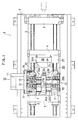
- a direct drive type mold clamping apparatus 1 which is mounted on a plastic injection molding machine, comprises a stationary platen 3 fixed to a platform 2 of the injection molding machine, and a rear platen 5 mounted on the platform for sliding motion over a predetermined distance for mold thickness adjustment.
- a movable platen 4 disposed between these platens 3 and 5 is arranged for reciprocal motion on the platform 2 and along four tie bars 6 extending between the platens 3, 5 in parallel to one another.
- a servomotor 10 Disposed between the movable platen 4 and the rear platen 5 are a servomotor 10, which is preferably comprised of an A.C. servomotor, and a crank mechanism 20 arranged to be driven by the servomotor 10 to reciprocate the movable platen 4.
- a pair of support members 7 and 7', projecting toward the movable platen 4, are integrally fixed to the rear platen 5 at left and right edge portions of an end face of the same platen at a side thereof facing the movable platen, respectively.
- a tie bar nut 8 which forms part of a mold thickness adjusting mechanism, is disposed at another end face, at a side remote from the movable platen, of the rear platen 5.
- the servomotor 10 which is of a type rotating at a low speed to generate a large torque, is connected with a servo circuit (not shown) which is in turn connected with a numerical control unit (not shown) of the injection molding machine.
- a pulse encoder 11 provided on the servomotor 10 is also connected with the servo circuit.
- the servomotor 10 is fixed at its flange portion 12 to an outer side face 7a of one 7 of the support members by means of bolts 9, and has its output shaft 13 which extends within a hole 7b formed in the support member 7 in the direction perpendicular to the direction along which the movable platen 4 is moved.
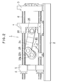
- the crank mechanism 20 has a driving shaft 21 which is comprised of a pair of shaft members 21a and 21b fabricated separately from each other. These driving shaft members 21a, 21b are disposed in alignment with the servomotor output shaft 13, and extend through holes 7b and 7'b respectively formed in the support members 7 and 7', and are rotatably supported by these members 7, 7' through bearings 30, etc. Further, the driving shaft member 21a, disposed at a side facing the servomotor, is spline-fitted at its outer end portion around the output shaft 13 for rotation in unison with the same output shaft. That is, the driving shaft 21 of the crank mechanism 20 is direct-coupled to the servomotor output shaft 13. For this spline connection, one of the elements 13, 21a is formed with keys and another is formed with associated keyways.
- the crank mechanism 20 further includes a first link 22 comprised of a pair of link members 22a and 22b which are separately fabricated from each other. These link members 22a, 22b are coupled to the driving shaft members 21a and 21b, respectively, for rotation in unison with these shaft members extending through holes 22a' and 22b' formed in inner end portions of the link members, respectively.
- the link members 22a, 22b are coupled to each other by means of a crank pin 23, which has opposite end portions fixedly fitted in holes (one of which is shown by reference numeral 22b'') formed in respective outer end portions of the link members.
- the crank mechanism 20 has a second link 24 extending between the driving shaft members 21a, 21b and between the link members 22a, 22b in the direction along which the movable platen is moved, and the crank pin 23 is rotatably fitted in a hole 24a formed in an end portion of the link 24 at a side thereof facing the rear platen.
- the second link 24 is formed at its end portion at a side thereof facing the movable platen with holes 24b into which fitted are respective end portions of a connecting rod 26 having opposite ends thereof supported by a bracket 25, which is fixed to an end face of the movable platen 4 at the side thereof facing the rear platen.
- the rear platen-side end portion of the second link 24 is so arranged as to be rotated in unison with the crank pin 23 around the driving shaft 21, resulting in reciprocal motion of the movable platen 4 coupled to the movable platen-side end of the second link 24 when the driving shaft 21 of the crank mechanism 20 rotates in unison with the servomotor output shaft 13.
- the servomotor 10 Upon start of mold closing operation, the servomotor 10 is driven to rotate in a predetermined rotational direction by means of the servo circuit which responds to a command signal supplied from the numerical control unit and a feedback signal supplied from the pulse encoder 11. With rotation of the servomotor, one driving shaft member 21a, fitted around and direct-coupled to the servomotor output shaft 13, of the driving shaft 21 of the crank mechanism 20, and another driving shaft member 22b are rotated in unison with the motor shaft 13, the shaft member 21b being coupled to the former shaft member 21a through one link member 22a of the first link 22, the crank pin 23 and another link member 22b.
- the crank pin 23 and the rear platen-side end portion of the second link 24 fitted therewith are rotated around the driving shaft 21, so that the movable platen-side end of the second link 24 is moved in the mold closing direction.
- the movable platen 4 coupled to the same link end through the connecting rod 26 and the bracket 25, is linearly moved along the tie bars 6 in the mold closing direction from its mold opening end position shown in Fig. 1.
- the mold clamping apparatus 1 equipped with the crank mechanism 20, coupled directly to the motor output shaft 13 and hence having a shortened power transmission path between itself and the motor 10 and great rigidity in power transmission responds to the operation of the motor 10 rapidly and accurately, so that the moving position of the movable platen 4 is accurately controlled, with fast response.
- a rotary motion force generated by the servomotor 10 is enlarged and converted into a linear motion force by the crank mechanism 20 to generate a great mold clamping force.
- the maximum mold clamping force on the order of about 30 tons is generated, with a tangential force of about 1.5 tons at the location at which the crank pin 23 is disposed, in the case that the maximum output torque of the servomotor 10 is 150 kgm, and the distances between the axis of the driving shaft 21 and that of the crank pin 23 and between the axis of the crank pin 23 and that of the connecting rod 26 are 100 mm and 350 mm, respectively.
- the present invention is not limited to the aforementioned embodiment, and various modifications thereof may be made.
- the servomotor 10 is comprised of an A.C. servomotor in the above-mentioned embodiment, a D.C. servomotor may be employed.
- the first link 22 may be formed into a disc.
Landscapes
- Engineering & Computer Science (AREA)
- Manufacturing & Machinery (AREA)
- Mechanical Engineering (AREA)
- Moulds For Moulding Plastics Or The Like (AREA)
Claims (6)
- Formklemmvorrichtung (1) mit Direktantrieb für den Gebrauch in einer Spritzgußmaschine, die eine bewegliche Traverse (4) hat, die umfaßt:
einen Servomotor (10), der eine Abgabewelle (13) hat; und
einen Kurbelmechanismus (20), der eine Antriebswelle (21) hat, die direkt mit der Abgabewelle (13) des Servomotors (10) gekoppelt ist, um die bewegliche Traverse (4) aufgrund der Drehbewegung des Servomotors (10) hin- und herzubewegen. - Formklemmvorrichtung mit Direktantrieb nach Anspruch 1, bei der die Einspritzformmaschine eine hintere Traverse (5) hat und der Servomotor (10) an der hinteren Traverse (5) befestigt ist.
- Formklemmvorrichtung mit Direktantrieb nach Anspruch 2, die weiter umfaßt:
ein Stützteil (7), das an der hinteren Traverse (5) befestigt ist und sich in Richtung auf die bewegliche Traverse (4) erstreckt;
wobei der Servomotor (10) am Stützteil (7) befestigt ist, wobei die Abgabewelle (13) des Servomotors (10), die sich in einer Richtung senkrecht zu einer Richtung ausdehnt, entlang welcher die bewegliche Traverse (4) bewegt wird, und die Abgabewelle (13) des Servomotors (10) und die Antriebswelle (13) des Servomotors (10) und die Antriebswelle (21) des Kurbelmechanismus (20) axial fluchtend ausgerichtet und ineinander eingepaßt sind, um sich gemeinsam zu drehen. - Formklemmvorrichtung mit Direktantrieb nach Anspruch 3, wobei der Stützteil (7) mit einem Loch (7b) gebildet ist, und wobei die Abgabewelle (13) des Servomotors (10) und die Antriebswelle (21) des Kurbelmechanismus (20) im Loch (7b) eingepaßt sind.
- Formklemmvorrichtung mit Direktantrieb nach einem der vorhergehenden Ansprüche, wobei der Kurbelmechanismus (20) ein erstes Zwischenstück (22) aufweist, das an seinem inneren Endteil mit der Antriebswelle (21) gekoppelt ist; einen Kurbelzapfen (23), der mit einem äußeren Endteil des ersten Zwischenstücks (22) gekoppelt ist; und ein zweites Zwischenstück (24), das einen Endteil hat, der mit dem Kurbelzapfen (23) gekoppelt ist, und ein anderen Endteil, der mit der beweglichen Traverse (4) gekoppelt ist.
- Formklemmvorrichtung mit Direktantrieb nach Anspruch 5, die weiter umfaßt:
einen Verbindungsstab (26), der entgegengesetzte Enden aufweist, die durch die bewegliche Traverse (4) gestützt sind;
bei der die Antriebswelle (21) ein Paar von Antriebswellenteilen (21a, 21b) hat, die axial fluchtend miteinander ausgerichtet sind; wobei das erste Zwischenstück (22) ein Paar von Zwischenstückteilen (22a, 22b) hat, die an ihren äußeren Endteilen durch den Kurbelzapfen (23) miteinander gekoppelt sind, wobei jeder Zwischenstückteil (22a, 22b) an seinem inneren Endteil mit einem der entsprechenden Antriebswellenteile (21a, 21b) gekoppelt ist, um sich im Einklang damit zu drehen;
wobei das zweite Zwischenstück (24), das sich zwischen dem Paar von Antriebswellenteilen (21a, 21b) und zwischen dem Paar von Zwischenstückteilen (22a, 22b) ausdehnt, einen Endteil hat, der durch den Kurbelzapfen (23) für eine relative Drehbewegung daran gestützt ist, und einen anderen Endteil, der durch den Verbindungsstab (26) für eine relative Drehbewegung daran gestützt ist.
Applications Claiming Priority (2)
| Application Number | Priority Date | Filing Date | Title |
|---|---|---|---|
| JP108952/88 | 1988-05-06 | ||
| JP63108952A JPH01280521A (ja) | 1988-05-06 | 1988-05-06 | ダイレクトドライブ式型締装置 |
Publications (3)
| Publication Number | Publication Date |
|---|---|
| EP0366810A1 EP0366810A1 (de) | 1990-05-09 |
| EP0366810A4 EP0366810A4 (en) | 1991-07-24 |
| EP0366810B1 true EP0366810B1 (de) | 1994-01-19 |
Family
ID=14497811
Family Applications (1)
| Application Number | Title | Priority Date | Filing Date |
|---|---|---|---|
| EP89904233A Expired - Lifetime EP0366810B1 (de) | 1988-05-06 | 1989-04-11 | Giessformklemmvorrichtung mit direktantrieb |
Country Status (5)
| Country | Link |
|---|---|
| EP (1) | EP0366810B1 (de) |
| JP (1) | JPH01280521A (de) |
| KR (1) | KR900700261A (de) |
| DE (1) | DE68912514T2 (de) |
| WO (1) | WO1989010830A1 (de) |
Families Citing this family (9)
| Publication number | Priority date | Publication date | Assignee | Title |
|---|---|---|---|---|
| JP2627215B2 (ja) * | 1990-11-22 | 1997-07-02 | オークマ株式会社 | トグル式型締機構 |
| JPH04369519A (ja) * | 1991-06-18 | 1992-12-22 | Sumitomo Jukikai Plast Mach Kk | 電動射出成形機の型締装置 |
| US5513977A (en) * | 1991-06-18 | 1996-05-07 | Sumitomo Heavy Industries, Ltd. | Clamping device for electric-powered injection molding machine |
| JP2839220B2 (ja) * | 1992-06-12 | 1998-12-16 | 住友重機械プラスチックマシナリー株式会社 | 電動射出成形機の型開閉装置 |
| NL1002691C2 (nl) * | 1996-03-22 | 1997-09-23 | Fico Bv | Pers voor het omhullen van electronische componenten en werkwijzen voor het gebruik van de pers. |
| ATE229419T1 (de) * | 1999-02-10 | 2002-12-15 | Netstal Ag Maschf Giesserei | Formschliesseinheit |
| AT410423B (de) * | 2000-06-21 | 2003-04-25 | Engel Gmbh Maschbau | Spritzgiessmaschine |
| DE102004018238B3 (de) * | 2004-04-15 | 2005-11-03 | Demag Ergotech Gmbh | Formschließeinheit |
| JP5953631B2 (ja) * | 2012-08-29 | 2016-07-20 | 株式会社ニイガタマシンテクノ | 射出成形機の型締装置 |
Family Cites Families (4)
| Publication number | Priority date | Publication date | Assignee | Title |
|---|---|---|---|---|
| CH630288A5 (en) * | 1978-06-05 | 1982-06-15 | Klaussner Hans Jurgen | Mechanical eccentric press |
| JPS61120715A (ja) * | 1984-11-16 | 1986-06-07 | Toshiba Mach Co Ltd | 電動機駆動射出成形機 |
| US4588364A (en) * | 1985-04-01 | 1986-05-13 | Husky Injection Molding Systems Ltd. | Clamp mechanism |
| JPS62156919A (ja) * | 1985-12-28 | 1987-07-11 | Toyo Kikai Kinzoku Kk | クランク装置の原点出し方法 |
-
1988
- 1988-05-06 JP JP63108952A patent/JPH01280521A/ja active Pending
-
1989
- 1989-04-11 WO PCT/JP1989/000391 patent/WO1989010830A1/ja not_active Ceased
- 1989-04-11 EP EP89904233A patent/EP0366810B1/de not_active Expired - Lifetime
- 1989-04-11 DE DE89904233T patent/DE68912514T2/de not_active Expired - Fee Related
- 1989-04-11 KR KR1019890701937A patent/KR900700261A/ko not_active Withdrawn
Also Published As
| Publication number | Publication date |
|---|---|
| KR900700261A (ko) | 1990-08-13 |
| DE68912514D1 (de) | 1994-03-03 |
| DE68912514T2 (de) | 1994-05-05 |
| JPH01280521A (ja) | 1989-11-10 |
| WO1989010830A1 (fr) | 1989-11-16 |
| EP0366810A1 (de) | 1990-05-09 |
| EP0366810A4 (en) | 1991-07-24 |
Similar Documents
| Publication | Publication Date | Title |
|---|---|---|
| US5052908A (en) | Toggle type mold clamping apparatus in an electrically-operated injection molding machine | |
| EP0427866B1 (de) | Spritzgiessvorrichtung vom typ mit zwei platten | |
| EP0213211B1 (de) | Formklemmungstruktur für spritzgiessmaschinen | |
| US6050804A (en) | Clamping apparatus for injection molding machine | |
| EP0275318B1 (de) | Direkt wirkendes formschliesssystem | |
| EP0271588A1 (de) | Direkt wirkendes formschliesssystem | |
| EP0366810A1 (de) | Giessformklemmvorrichtung mit direktantrieb | |
| JP2612094B2 (ja) | 成形機の駆動装置 | |
| US5370524A (en) | Clamping unit and method for an injection molding machine | |
| US6004490A (en) | Method of using an improved clamping unit in an injection molding machine | |
| EP0451294B1 (de) | Spritzgiessvorrichtung vom kurbeltyp | |
| JP2649098B2 (ja) | コア駆動装置内蔵射出成形機 | |
| US6796787B2 (en) | Product ejecting apparatus and method for an injection molding machine | |
| EP0381770B1 (de) | Formschliessvorrichtung vom typ mit zwei platten | |
| US4828476A (en) | Direct-pressure type mold clamping mechanism of an injection-molding machine | |
| US20030113400A1 (en) | Servo-driven clamping unit for use in injection molding machine | |
| EP1129837B1 (de) | Antriebsvorrichtung für Spritzgiessmaschine | |
| JP2002200658A (ja) | 射出成形機の型締め装置 | |
| JP3517747B2 (ja) | 駆動装置及び射出成形機 | |
| JP3496089B2 (ja) | 射出成形機の駆動装置 | |
| JPH0222025A (ja) | 射出成形機の電動射出装置 | |
| JPH0639958Y2 (ja) | 射出成形機の製品突出装置 | |
| JP3130824B2 (ja) | エジェクタ装置 | |
| JPH072186Y2 (ja) | 射出成形機のエジェクタ装置 | |
| JPH10286848A (ja) | インラインスクリュー式の射出成形機 |
Legal Events
| Date | Code | Title | Description |
|---|---|---|---|
| PUAI | Public reference made under article 153(3) epc to a published international application that has entered the european phase |
Free format text: ORIGINAL CODE: 0009012 |
|
| 17P | Request for examination filed |
Effective date: 19891120 |
|
| AK | Designated contracting states |
Kind code of ref document: A1 Designated state(s): CH DE FR GB IT LI |
|
| A4 | Supplementary search report drawn up and despatched |
Effective date: 19910606 |
|
| AK | Designated contracting states |
Kind code of ref document: A4 Designated state(s): CH DE FR GB IT LI |
|
| 17Q | First examination report despatched |
Effective date: 19921005 |
|
| GRAA | (expected) grant |
Free format text: ORIGINAL CODE: 0009210 |
|
| AK | Designated contracting states |
Kind code of ref document: B1 Designated state(s): CH DE FR GB IT LI |
|
| PG25 | Lapsed in a contracting state [announced via postgrant information from national office to epo] |
Ref country code: LI Effective date: 19940119 Ref country code: FR Effective date: 19940119 Ref country code: CH Effective date: 19940119 |
|
| REF | Corresponds to: |
Ref document number: 68912514 Country of ref document: DE Date of ref document: 19940303 |
|
| ITF | It: translation for a ep patent filed | ||
| REG | Reference to a national code |
Ref country code: CH Ref legal event code: PL |
|
| EN | Fr: translation not filed | ||
| PLBE | No opposition filed within time limit |
Free format text: ORIGINAL CODE: 0009261 |
|
| STAA | Information on the status of an ep patent application or granted ep patent |
Free format text: STATUS: NO OPPOSITION FILED WITHIN TIME LIMIT |
|
| 26N | No opposition filed | ||
| PGFP | Annual fee paid to national office [announced via postgrant information from national office to epo] |
Ref country code: GB Payment date: 19990415 Year of fee payment: 11 |
|
| PGFP | Annual fee paid to national office [announced via postgrant information from national office to epo] |
Ref country code: DE Payment date: 20000410 Year of fee payment: 12 |
|
| PG25 | Lapsed in a contracting state [announced via postgrant information from national office to epo] |
Ref country code: GB Free format text: LAPSE BECAUSE OF NON-PAYMENT OF DUE FEES Effective date: 20000411 |
|
| GBPC | Gb: european patent ceased through non-payment of renewal fee |
Effective date: 20000411 |
|
| PG25 | Lapsed in a contracting state [announced via postgrant information from national office to epo] |
Ref country code: DE Free format text: LAPSE BECAUSE OF NON-PAYMENT OF DUE FEES Effective date: 20020201 |
|
| PG25 | Lapsed in a contracting state [announced via postgrant information from national office to epo] |
Ref country code: IT Free format text: LAPSE BECAUSE OF NON-PAYMENT OF DUE FEES Effective date: 20050411 |