EP0451330A1 - Procédé pour le calibrage ou recalibrage automatique des mesures d'une grandeur physique - Google Patents
Procédé pour le calibrage ou recalibrage automatique des mesures d'une grandeur physique Download PDFInfo
- Publication number
- EP0451330A1 EP0451330A1 EP90120975A EP90120975A EP0451330A1 EP 0451330 A1 EP0451330 A1 EP 0451330A1 EP 90120975 A EP90120975 A EP 90120975A EP 90120975 A EP90120975 A EP 90120975A EP 0451330 A1 EP0451330 A1 EP 0451330A1
- Authority
- EP
- European Patent Office
- Prior art keywords
- value
- partial measuring
- sensor
- measuring range
- physical quantity
- Prior art date
- Legal status (The legal status is an assumption and is not a legal conclusion. Google has not performed a legal analysis and makes no representation as to the accuracy of the status listed.)
- Granted
Links
- 238000005259 measurement Methods 0.000 title claims abstract description 42
- 238000000034 method Methods 0.000 title claims abstract description 35
- 230000003247 decreasing effect Effects 0.000 claims description 2
- 230000000630 rising effect Effects 0.000 abstract 1
- 230000006698 induction Effects 0.000 description 10
- 230000003287 optical effect Effects 0.000 description 5
- 241001136792 Alle Species 0.000 description 4
- 210000002023 somite Anatomy 0.000 description 3
- 238000006073 displacement reaction Methods 0.000 description 1
- 238000011156 evaluation Methods 0.000 description 1
- 238000013213 extrapolation Methods 0.000 description 1
- 230000001960 triggered effect Effects 0.000 description 1
Images

Classifications
-
- G—PHYSICS
- G12—INSTRUMENT DETAILS
- G12B—CONSTRUCTIONAL DETAILS OF INSTRUMENTS, OR COMPARABLE DETAILS OF OTHER APPARATUS, NOT OTHERWISE PROVIDED FOR
- G12B13/00—Calibrating of instruments and apparatus
-
- G—PHYSICS
- G01—MEASURING; TESTING
- G01D—MEASURING NOT SPECIALLY ADAPTED FOR A SPECIFIC VARIABLE; ARRANGEMENTS FOR MEASURING TWO OR MORE VARIABLES NOT COVERED IN A SINGLE OTHER SUBCLASS; TARIFF METERING APPARATUS; MEASURING OR TESTING NOT OTHERWISE PROVIDED FOR
- G01D5/00—Mechanical means for transferring the output of a sensing member; Means for converting the output of a sensing member to another variable where the form or nature of the sensing member does not constrain the means for converting; Transducers not specially adapted for a specific variable
- G01D5/26—Mechanical means for transferring the output of a sensing member; Means for converting the output of a sensing member to another variable where the form or nature of the sensing member does not constrain the means for converting; Transducers not specially adapted for a specific variable characterised by optical transfer means, i.e. using infrared, visible, or ultraviolet light
Definitions
- the invention relates to a method for the automatic calibration or post-calibration of measurements of a physical quantity according to the preamble of claim 1 and to an arrangement for carrying out the method.
- Such methods are suitable, for example, for measuring distances, magnetic fields, pressure differences, etc., if the output characteristic curve of the sensor used for the measurement is not linear and is either unknown from the start or unstable, so that in the latter case it is, although originally known , has meanwhile changed in an unknown manner as a function of time, temperature or another quantity in such a way that it is again unknown and must be re-verified.
- values of a function f [x] of the values x of a physical quantity are measured.
- a method of the type mentioned in the preamble of claim 1 can be found in the publication "Applied Optics, 1 February 1989, Vol. 28, No. 3, pages 419 to 420, Loss compensated fiber-optic displacement sensor including a lens, E. Bois, SJ Huard and G. Boisde ", in which a self-calibrating and loss-compensating optical distance sensor is described.
- the distance sensor contains for the purpose of self-calibration two light guides, the first ends of which are axially displaced relative to one another and are arranged opposite a light-reflecting surface of a movable body which moves along the optical axis of the light guide.
- the second end of each light guide is alternately connected to a light emitting diode or to a phototodiode.
- Each light emitting diode emits light and is alternately excited in order to evaluate two signals subsequently detected by the photodiodes using a microcomputer.
- the transmitted light reaches the light-reflecting surface via the associated light guide and the reflected light then reaches the photodiodes via light guides, the output signals of which are fed to the microcomputer.
- the microcomputer in turn keeps the reference signal sent by the light emitting diode constant via a digital / analog converter and calibrates the measuring arrangement by forming and evaluating the ratio of the sum and the difference between the two detected signals.
- the ratio in the vicinity of the zero point is proportional to the desired value of the distance if the presence of parabolic output characteristic curves is assumed for the sensors.
- the invention has for its object to use two approximately identical sensors to find a method of the type mentioned, which allows the output characteristic of a first of the two sensors without great demands on the shape of the output characteristics of the sensors and without further large restrictive conditions to calibrate or recalibrate using the measurement results of the second sensor.
- the arrangements shown in the drawing each contain a first sensor 1, a second sensor 2, a computer 3 and a display 4, which are contained together in a measuring arrangement 5.
- any physical quantity to be measured are referred to below as x.
- the assumption applies that the physical quantity is a spatial distance between a movable body 6, which in turn has a front surface 7, and an effective front surface of the Sensor 1 is, whose values are denoted by L, so that x L applies.
- the two sensors 1 and 2 determine values x of the same physical size.
- Sensor 1 has an output signal f [x] and sensor 2 has an output signal g [x], both of which are a function of the values x of the physical quantity.
- the two sensors 1 and 2 are constructed almost identically, so that their output signals f [x] and g [x] have an approximately identical, but initially unknown course as a function of the values x of the physical quantity.
- the two output characteristic curves of sensors 1 and 2 in which the values x are each plotted as abscissa values, are either unknown or, if they were known, have become unknown since they are unstable.
- the two sensors 1 and 2 determine values of the physical quantity, which differ from one another by a predetermined constant difference value a of the physical quantity.
- the difference value a is stored in the computer 3.
- the outputs of the two sensors 1 and 2 are each connected to an input of the computer 3, so that the latter receives the output signals f [x] and y [x] of the two sensors 1 and 2 as measurement data, which it evaluates in order to use them to find the desired value x of the physical quantity.
- the determined value x is then fed to an output of the computer 3 for further evaluation or display. From the output of the computer 3, the determined value x of the physical quantity z. B. then an input of the display 4, in which it is displayed.
- any initial value x o of the value x of the physical Size is known, be it that it is specified, or that it was determined with a precision measuring device at the start of the measurements.
- the initial value x o includes a value f [x o ] of the output signal f [x] of the sensor 1.
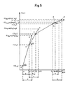
- the values of f [x o ] and x o are stored in the computer 3 and set the coordinate values of a starting point A (see FIG. 5 ) represents the output characteristic of sensors 1 and 2.
- At least the output characteristic curve of the sensor 1 is divided into partial measuring ranges which are provided with serial numbers k, where k is 0, 1, 2, 3, etc.
- the width of the partial measuring ranges measured in the direction of the abscissa values is chosen to be the same size as the predetermined constant difference value a in the values of physical quantity x determined by sensors 1 and 2.
- the measurement results of the sensor 2 are used exclusively in the course of the measurements, starting from the known coordinate values f [x o ] and x o of the starting point A of the output characteristic of the sensor 1, a known part of this output characteristic in the direction of increasing values x of the physical quantity by new ones to expand known partial measuring ranges more and more, whereby two neighboring known partial measuring ranges each overlap for at least one abscissa value of the output characteristic curve, ie for a value x k of the physical quantity.
- the sensor 2 thus automatically and specifically takes over the calibration or re-calibration of the measurements of the sensor 1 by continuously expanding the known characteristic curve range of the sensor 1 and thus the sensor 1 getting to know its own output characteristic curve.
- the sensor 1 determines the sought value x of the physical quantity only in those partial measuring ranges of its output characteristic curve in which the values of the output characteristic curve have already been determined with the aid of the measurement results of the sensor 2.
- 1 consists of the two sensors 1 and 2, the computer 3 and the display 4.
- FIG. 2 shows an optical variant of the distance measuring arrangement shown in FIG. 1.
- the front surface 7 of the movable body 6 is preferably a reflective surface which is irradiated with visible or invisible light by a light transmitter 9 via a first light guide 10.
- the light transmitter 9 is e.g. B. a light-emitting diode powered by a current, which is controlled or fed via the computer 3.
- the front surface 7 is located at a distance L or L + a from the front surfaces of two further light guides 11 and 12, the front surfaces of which, measured parallel to the direction of the distance L, are arranged offset from one another by a distance a.
- the two light guides 11 and 12 extend z. B.
- the light guide 11 the front surface of which is located at a distance L from the front surface 7, is connected to the sensor 1, while the light guide 12 is connected to the sensor 2.
- the front surfaces of the light guides 11 and 12 facing the front surface 7 represent the effective front surfaces of the two sensors 1 and 2.
- the two sensors 1 and 2, the computer 3, the display 4, the light transmitter 9 and the three light guides 10 to 12 form in FIG 2 shows the measuring arrangement 5.
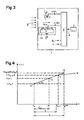
- a magnetic induction B is measured in the magnetic field measuring arrangement shown in FIG. 3, which mainly consists of a measuring arrangement 5.
- the measuring arrangement 5 consists of the two sensors 1 and 2, the computer 3, the display 4 and a permanent magnet 14.
- the sensors 1 and 2 are preferably Hall elements this time, both of which are supplied with the same and constant current.
- the sensor 1 measures only the magnetic induction B, while the sensor 2 measures a magnetic induction B + a, a small differential induction a being generated by the permanent magnet 14.
- the north pole is denoted by N and the south pole by S.
- the permanent magnet 14 is spatially arranged such that the magnetic induction B to be measured and the magnetic differential induction a of the permanent magnet 14 add up.
- acoustic, pneumatic or microwave solutions can also be used, in which case sensors 1 and 2 must then be replaced by corresponding acoustic, pneumatic or microwave sensors.
- the 4 shows the output signal f [x] of the sensor 1 as a function of the values x of the physical quantity to be measured within a partial measuring range, which has an arbitrary serial number k.
- the partial measuring range has a width in the direction of the abscissa values which is the same size as the known predetermined difference value a of the physical quantity.
- the difference value a is chosen to be so small that an associated part of the Output characteristic of sensor 1 can be assumed to be linear.
- a starting point Q of the associated linear part of the output characteristic has the coordinate values f [x k ] and x k
- the z. B. has a sequential number k, the existing lowest value x k is greater than zero and less than a predetermined constant value b, there is no switchover to another partial measuring range.
- the predetermined constant value b is chosen to be smaller than the predetermined constant difference value a of the physical quantity and stored in the computer 3. Reaches or exceeds a positive value of the difference ⁇ x, however, e.g. B. at measuring point T, the predetermined constant value b, then there is always a switchover from the currently applicable partial measuring range to an adjacent higher partial measuring range.
- the value of the difference ⁇ x is positive and greater than or equal to the predetermined constant value b, then a switch is made to a new adjacent partial measuring range, which is in the direction of increasing values of the physical quantity, and the serial number k + 1 of the new partial measuring range is changed to selected a value one greater than the serial number k of the currently applicable partial measuring range.
- the measuring point T which lies on the straight line QR and which has the coordinate values f [x k + 1 ] and x k + 1 , is switched from the applicable partial measuring range with the serial number k to the next higher partial measuring range, which has a sequential number k + 1 has, since the value of the difference ⁇ x is positive and greater than b.
- the starting point of the part TW of the characteristic of the new partial measuring range with the serial number k + 1 is then the measuring point T, while its end point, which is no longer shown in FIG. 4, is the coordinate values f [x k + 1 + a] ⁇ y has [x k + 1 ] and x k + 1 + a.
- a switch is made to a new neighboring partial measuring range, which is in the direction of decreasing values of the physical quantity, and the serial number k-1 of the new partial measuring range is chosen to be one less than the current one Number k of the currently applicable partial measuring range, whereby k-1 must always be greater than or equal to zero.
- the coordinates of the starting points A, C, E, Q and T of the parts of the characteristic mentioned are f [x k ] and x k and those of the end points B, D, P and R are f [x k + a] ⁇ y [x k ] and x k + a, where k each has the value of the serial number of the associated partial measuring range.
- the starting point A which is also the starting point of the entire characteristic curve, thus has the coordinate values Initial values f [x o ] and x o , which are already known at the start of the method and are then also stored in the computer 3.
- the starting points C, E, Q and T are measuring points that each belong to the parts of the characteristic curve of two adjacent partial measuring ranges, namely the partial measuring range with the associated serial number k and the previous partial measuring range with the serial number k-1.
- the new partial measuring range is a measuring range whose linear part of the output characteristic curve was previously unknown.
- the starting point of the output characteristic in the new partial measuring range then receives the just determined value x k of the physical quantity and the associated value of the output signal f [x k ] of the sensor 1 as coordinate values.
- the end point of the output characteristic in the new partial measuring range receives the coordinate values that obtained by the sensor 1, the value x k + a of the physical quantity and the value of the output signal y [x k ] ⁇ f [x k + a] of the sensor 2, which is increased by the difference value a.
- the value f [x k ] of the output signal f [x] of the sensor 1 that is currently pending is triggered for the value x k of the physical variable that triggers the switch and for the value x k + a of the physical quantity, the just present value y [x k ]) of the output signal y [x] of the sensor 2 is determined.
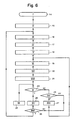
- variable m specifies the highest value of the serial number k of the partial measuring ranges that has been achieved in the course of the measurements.
- the value x k of the physical quantity that triggers the changeover and the associated value f [x k ] of the output signal f [x] of the sensor 1 are the known coordinate values x o and f [x o ] ) of the starting point A of the output characteristic.
- three decision blocks 23, 24 and 25 and two function blocks 26 and 27 are also present in the flowchart shown in FIG. 6, each of which contains one of the functions X, XII, XIV, XI and XIII in the order given. 6, the no output of the function blocks 23 to 25 is each identified with NY (" N ot Y es), while their yes outputs are each identified with Y ( Y es).
- the output signal of the function block 21 feeds the input of the decision block 23, the no output NY of which leads to the input of the decision block 24, while its yes output Y is connected via the function block 26 to the input of the decision block 25 is.
- the yes output Y of the decision block 24 is routed to the input of the function block 27, the output of which is connected to the no outputs NY of the decision blocks 24 and 25 and to the input of the function block 19.
- the yes output Y of the decision block 25 is connected to the input of the function block 16.
- the function blocks 14 and 15 are only once in the program Go through the beginning of the process and serve to actively set the value of the physical quantity x to the value x o , e.g. B. by switching off the magnetic induction to be measured or by moving the movable body until contact with the mechanical stop 8, and to store the values of x o , a and b already known at the beginning in the computer 3 and the values of k and reset m to zero.
- the function blocks 16 to 18 are run through at the beginning of each new, previously unknown partial measuring range in order to use the values of x k , f [x k ] and y [x k ] to determine the new value tg ⁇ k of the inclination of the linear part of the Determine the characteristic curve in the new, previously unknown partial measuring range.
- the inclination tg ⁇ k of the associated linear part of the output characteristic curve of sensor 1 is thus determined in the course of the method, and thus the curve of the entire output characteristic curve of sensor 1 for sub-measuring ranges strung together.
- the previously valid value of m is then increased by a value one, since the new partial measuring range is no longer unknown.
- the function and decision blocks 19 to 27 are run through for each measurement and serve on the one hand to determine the values of x and ⁇ x and on the other hand to check whether the value of the difference ⁇ x is greater than or equal to the predetermined value b or less than zero. If no, then no partial measuring range is switched. If so, then a switchover from the applicable partial measuring range to a higher or lower partial measuring range takes place by incrementing or decrementing the applicable value of k by a value of one. If an incremented value of k is also greater than the valid value of m or equal to this value, the new partial measuring range is an as yet unknown partial measuring range and the program returns to the input of function block 16 to determine its previously unknown value of tg ⁇ k . In all other cases, on the other hand, there is either a switchover to a known partial measuring range or no switchover to one Partial measuring range and the program returns to the input of the function block 19, where it is then available for another measurement.
- the program run is subsequently divided into groups of program runs, each group belonging to such successive measurements whose measurement results are all in the same partial measuring range with a serial number k.
- the associated part of the output characteristic of sensor 1 is first determined with the aid of the measurement results from sensor 2.
Landscapes
- Physics & Mathematics (AREA)
- General Physics & Mathematics (AREA)
- Indication And Recording Devices For Special Purposes And Tariff Metering Devices (AREA)
- Testing Or Calibration Of Command Recording Devices (AREA)
- Length Measuring Devices With Unspecified Measuring Means (AREA)
- Investigating Or Analysing Materials By Optical Means (AREA)
- Paper (AREA)
- Extrusion Moulding Of Plastics Or The Like (AREA)
Applications Claiming Priority (2)
| Application Number | Priority Date | Filing Date | Title |
|---|---|---|---|
| CH103090 | 1990-03-28 | ||
| CH1030/90 | 1990-03-28 |
Publications (2)
| Publication Number | Publication Date |
|---|---|
| EP0451330A1 true EP0451330A1 (fr) | 1991-10-16 |
| EP0451330B1 EP0451330B1 (fr) | 1994-09-21 |
Family
ID=4200812
Family Applications (1)
| Application Number | Title | Priority Date | Filing Date |
|---|---|---|---|
| EP90120975A Expired - Lifetime EP0451330B1 (fr) | 1990-03-28 | 1990-11-02 | Procédé pour le calibrage ou recalibrage automatique des mesures d'une grandeur physique |
Country Status (6)
| Country | Link |
|---|---|
| US (1) | US5276631A (fr) |
| EP (1) | EP0451330B1 (fr) |
| JP (1) | JPH04223217A (fr) |
| AT (1) | ATE112086T1 (fr) |
| DE (1) | DE59007272D1 (fr) |
| DK (1) | DK0451330T3 (fr) |
Cited By (1)
| Publication number | Priority date | Publication date | Assignee | Title |
|---|---|---|---|---|
| DE102020206261A1 (de) | 2020-05-19 | 2021-11-25 | Robert Bosch Gesellschaft mit beschränkter Haftung | Verfahren zum Übertragen einer Sensorcharakteristik |
Families Citing this family (25)
| Publication number | Priority date | Publication date | Assignee | Title |
|---|---|---|---|---|
| US6571132B1 (en) | 1999-09-28 | 2003-05-27 | Rosemount Inc. | Component type adaptation in a transducer assembly |
| US6765968B1 (en) | 1999-09-28 | 2004-07-20 | Rosemount Inc. | Process transmitter with local databus |
| US6487912B1 (en) | 1999-09-28 | 2002-12-03 | Rosemount Inc. | Preinstallation of a pressure sensor module |
| US7134354B2 (en) * | 1999-09-28 | 2006-11-14 | Rosemount Inc. | Display for process transmitter |
| US6484107B1 (en) * | 1999-09-28 | 2002-11-19 | Rosemount Inc. | Selectable on-off logic modes for a sensor module |
| WO2001024594A2 (fr) | 1999-09-28 | 2001-04-05 | Rosemount Inc. | Adaptateur de circuit de mesure isole du milieu environnant |
| US6546805B2 (en) | 2000-03-07 | 2003-04-15 | Rosemount Inc. | Process fluid transmitter with an environmentally sealed service block |
| US6504489B1 (en) | 2000-05-15 | 2003-01-07 | Rosemount Inc. | Process control transmitter having an externally accessible DC circuit common |
| US6688119B2 (en) | 2000-12-22 | 2004-02-10 | General Electric Company | Methods and apparatus for increasing appliance measuring system accuracy |
| US6585061B2 (en) * | 2001-10-15 | 2003-07-01 | Precision Drilling Technology Services Group, Inc. | Calculating directional drilling tool face offsets |
| US7773715B2 (en) | 2002-09-06 | 2010-08-10 | Rosemount Inc. | Two wire transmitter with isolated can output |
| US7109883B2 (en) * | 2002-09-06 | 2006-09-19 | Rosemount Inc. | Low power physical layer for a bus in an industrial transmitter |
| US7525419B2 (en) * | 2006-01-30 | 2009-04-28 | Rosemount Inc. | Transmitter with removable local operator interface |
| US7865038B2 (en) * | 2006-04-04 | 2011-01-04 | Synaptics Incorporated | Resolution and sensitivity balance metric |
| US8334788B2 (en) * | 2010-03-04 | 2012-12-18 | Rosemount Inc. | Process variable transmitter with display |
| GB2489722B (en) | 2011-04-06 | 2017-01-18 | Precitec Optronik Gmbh | Apparatus and method for determining a depth of a region having a high aspect ratio that protrudes into a surface of a semiconductor wafer |
| DE102011051146B3 (de) | 2011-06-17 | 2012-10-04 | Precitec Optronik Gmbh | Prüfverfahren zum Prüfen einer Verbindungsschicht zwischen waferförmigen Proben |
| DE102012111008B4 (de) | 2012-11-15 | 2014-05-22 | Precitec Optronik Gmbh | Optisches Messverfahren und optische Messvorrichtung zum Erfassen einer Oberflächentopographie |
| TWI638131B (zh) * | 2013-06-17 | 2018-10-11 | 普雷茨特光電有限公司 | 用於獲取距離差之光學量測裝置及光學量測方法 |
| US10234265B2 (en) | 2016-12-12 | 2019-03-19 | Precitec Optronik Gmbh | Distance measuring device and method for measuring distances |
| US10502760B2 (en) | 2017-04-11 | 2019-12-10 | General Electric Company | Pitot-static air data test system with pilot and co-pilot verification |
| DE102017126310A1 (de) | 2017-11-09 | 2019-05-09 | Precitec Optronik Gmbh | Abstandsmessvorrichtung |
| DE102018130901A1 (de) | 2018-12-04 | 2020-06-04 | Precitec Optronik Gmbh | Optische Messeinrichtung |
| EP4168734B1 (fr) | 2020-06-19 | 2025-09-24 | Precitec Optronik GmbH | Appareil de mesure confocal chromatique |
| CN114166109B (zh) * | 2021-12-15 | 2022-10-28 | 珠海格力电器股份有限公司 | 高度传感器标定方法、装置及系统 |
Citations (4)
| Publication number | Priority date | Publication date | Assignee | Title |
|---|---|---|---|---|
| US3937574A (en) * | 1973-10-29 | 1976-02-10 | Kaman Sciences Corporation | System and method for measuring distance |
| US4576035A (en) * | 1984-01-05 | 1986-03-18 | Cordis Corporation | Self-calibrating differential condition sensor |
| EP0184632A2 (fr) * | 1984-12-13 | 1986-06-18 | Bodenseewerk Gerätetechnik GmbH | Dispositif d'initialisation et/ou de recalibrage d'un navigateur inertiel répétiteur |
| WO1987001446A1 (fr) * | 1985-09-04 | 1987-03-12 | The Foxboro Company | Ameliorations apportees a des systemes indicateurs de niveau de reservoirs hydrostatiques |
Family Cites Families (5)
| Publication number | Priority date | Publication date | Assignee | Title |
|---|---|---|---|---|
| US4488813A (en) * | 1982-04-29 | 1984-12-18 | Mechanical Technology Incorporated | Reflectivity compensating system for fiber optic sensor employing dual probes at a fixed gap differential |
| US4446715A (en) * | 1982-06-07 | 1984-05-08 | Camino Laboratories, Inc. | Transducer calibration system |
| FR2615279B1 (fr) * | 1987-05-11 | 1990-11-02 | Commissariat Energie Atomique | Capteur de deplacement a fibres optiques decalees |
| US5051578A (en) * | 1989-11-15 | 1991-09-24 | Slemon Charles S | Self calibrating fiber optic sensor system with optimized throughput |
| US5162661A (en) * | 1990-02-08 | 1992-11-10 | Pioneer Electronic Corporation | Position detector for maintaining a fixed distance between two objects |
-
1990
- 1990-11-02 DK DK90120975.9T patent/DK0451330T3/da active
- 1990-11-02 DE DE59007272T patent/DE59007272D1/de not_active Expired - Fee Related
- 1990-11-02 EP EP90120975A patent/EP0451330B1/fr not_active Expired - Lifetime
- 1990-11-02 AT AT90120975T patent/ATE112086T1/de active
-
1991
- 1991-03-01 US US07/662,848 patent/US5276631A/en not_active Expired - Fee Related
- 1991-03-22 JP JP3057523A patent/JPH04223217A/ja active Pending
Patent Citations (4)
| Publication number | Priority date | Publication date | Assignee | Title |
|---|---|---|---|---|
| US3937574A (en) * | 1973-10-29 | 1976-02-10 | Kaman Sciences Corporation | System and method for measuring distance |
| US4576035A (en) * | 1984-01-05 | 1986-03-18 | Cordis Corporation | Self-calibrating differential condition sensor |
| EP0184632A2 (fr) * | 1984-12-13 | 1986-06-18 | Bodenseewerk Gerätetechnik GmbH | Dispositif d'initialisation et/ou de recalibrage d'un navigateur inertiel répétiteur |
| WO1987001446A1 (fr) * | 1985-09-04 | 1987-03-12 | The Foxboro Company | Ameliorations apportees a des systemes indicateurs de niveau de reservoirs hydrostatiques |
Non-Patent Citations (3)
| Title |
|---|
| APPLIED OPTICS, Band 28, Nr. 3, 1. Februar 1989; E. BOIS et al.: "Loss compensated fiber-optic displacement sensor including a lens" * |
| RADIOELEKTRON, Band 55, Nr. 7, 1980, Seiten 55-65; E.A. ZAK et al. * |
| WPIL, FILE SUPPLIER, AN=84-268377, Derwent Publications, Ltd, London, GB; & SU-A-1 076 764 (KUIBYSHEV) 28-12-1982 * |
Cited By (1)
| Publication number | Priority date | Publication date | Assignee | Title |
|---|---|---|---|---|
| DE102020206261A1 (de) | 2020-05-19 | 2021-11-25 | Robert Bosch Gesellschaft mit beschränkter Haftung | Verfahren zum Übertragen einer Sensorcharakteristik |
Also Published As
| Publication number | Publication date |
|---|---|
| ATE112086T1 (de) | 1994-10-15 |
| US5276631A (en) | 1994-01-04 |
| EP0451330B1 (fr) | 1994-09-21 |
| JPH04223217A (ja) | 1992-08-13 |
| DK0451330T3 (da) | 1995-02-20 |
| DE59007272D1 (de) | 1994-10-27 |
Similar Documents
| Publication | Publication Date | Title |
|---|---|---|
| EP0451330B1 (fr) | Procédé pour le calibrage ou recalibrage automatique des mesures d'une grandeur physique | |
| EP0157135B1 (fr) | Procédé de visualisation d'une valeur de mesure | |
| DE3443176C1 (de) | Verfahren zur Kalibrierung eines elektronischen Positionsgebers | |
| DE2730715C2 (de) | Einrichtung zur Längenmessung | |
| EP2072965B1 (fr) | Dispositif de mesure de position et procédé de détermination de la position absolue | |
| DE3144334C2 (de) | Wegmeßeinrichtung mit Referenzmarken | |
| DE19800354A1 (de) | Vorrichtung und Verfahren zur Entfernungsmessung | |
| DE3346502A1 (de) | Positionsabtasteinrichtung | |
| DE60029288T2 (de) | Biegevorrichtung und deren Betriebsverfahren | |
| DE2521618B1 (de) | Vorrichtung zum Messen oder Einstellen von zweidimensionalen Lagekoordinaten | |
| DE3206046A1 (de) | Fluessigkeitsniveauanzeiger | |
| EP1816488A1 (fr) | Dispositif optoélectronique et son procédé de fonctionnement | |
| DE1806312C3 (de) | Leuchtweiteregler fur Fahrzeugscheinwerfer | |
| DE69705742T2 (de) | Verfahren zur optimierung der berührpunktserkennung eines kapazitiven berührungssensors | |
| DE3914739A1 (de) | Inkrementale positionsmesseinrichtung mit referenzmarken | |
| DE3407942C2 (fr) | ||
| DE2315471C3 (de) | Stellungsgeber für elektrische Nachführeinrichtungen bei Registriersystemen | |
| DE3941309A1 (de) | Vorrichtung sowie verfahren zum messen eines objektes | |
| DE1022032B (de) | Interferometer zu Messzwecken | |
| DE3490407C1 (de) | Fachkamera | |
| EP0596535A2 (fr) | Méthode de mesure à haute résolution de positions linéaires et tournantes | |
| DD225497A1 (de) | Einrichtung und verfahren zum messen und einstellen von laengen | |
| DE4232171C2 (de) | Verfahren und Vorrichtung zur relativen Positionsbestimmung eines fahrerlosen Fahrzeuges | |
| DE2838121B2 (de) | Verfahren zur Scharfeinstellung einer Optik | |
| CH355618A (de) | Verfahren zum Messen oder Einstellen der relativen Lage zweier Körper |
Legal Events
| Date | Code | Title | Description |
|---|---|---|---|
| PUAI | Public reference made under article 153(3) epc to a published international application that has entered the european phase |
Free format text: ORIGINAL CODE: 0009012 |
|
| AK | Designated contracting states |
Kind code of ref document: A1 Designated state(s): AT BE CH DE DK ES FR GB GR IT LI LU NL SE |
|
| 17P | Request for examination filed |
Effective date: 19911104 |
|
| RAP1 | Party data changed (applicant data changed or rights of an application transferred) |
Owner name: LANDIS & GYR BUSINESS SUPPORT AG |
|
| 17Q | First examination report despatched |
Effective date: 19940302 |
|
| GRAA | (expected) grant |
Free format text: ORIGINAL CODE: 0009210 |
|
| AK | Designated contracting states |
Kind code of ref document: B1 Designated state(s): AT BE CH DE DK ES FR GB GR IT LI LU NL SE |
|
| PG25 | Lapsed in a contracting state [announced via postgrant information from national office to epo] |
Ref country code: IT Free format text: LAPSE BECAUSE OF FAILURE TO SUBMIT A TRANSLATION OF THE DESCRIPTION OR TO PAY THE FEE WITHIN THE PRE;WARNING: LAPSES OF ITALIAN PATENTS WITH EFFECTIVE DATE BEFORE 2007 MAY HAVE OCCURRED AT ANY TIME BEFORE 2007. THE CORRECT EFFECTIVE DATE MAY BE DIFFERENT FROM THE ONE RECORDED.SCRIBED TIME-LIMIT Effective date: 19940921 Ref country code: NL Effective date: 19940921 Ref country code: GB Effective date: 19940921 Ref country code: GR Free format text: LAPSE BECAUSE OF FAILURE TO SUBMIT A TRANSLATION OF THE DESCRIPTION OR TO PAY THE FEE WITHIN THE PRESCRIBED TIME-LIMIT Effective date: 19940921 Ref country code: BE Effective date: 19940921 Ref country code: FR Effective date: 19940921 Ref country code: ES Free format text: THE PATENT HAS BEEN ANNULLED BY A DECISION OF A NATIONAL AUTHORITY Effective date: 19940921 |
|
| REF | Corresponds to: |
Ref document number: 112086 Country of ref document: AT Date of ref document: 19941015 Kind code of ref document: T |
|
| REF | Corresponds to: |
Ref document number: 59007272 Country of ref document: DE Date of ref document: 19941027 |
|
| PG25 | Lapsed in a contracting state [announced via postgrant information from national office to epo] |
Ref country code: AT Effective date: 19941102 |
|
| PG25 | Lapsed in a contracting state [announced via postgrant information from national office to epo] |
Ref country code: LU Free format text: LAPSE BECAUSE OF NON-PAYMENT OF DUE FEES Effective date: 19941130 |
|
| RAP2 | Party data changed (patent owner data changed or rights of a patent transferred) |
Owner name: LANDIS & GYR TECHNOLOGY INNOVATION AG |
|
| PG25 | Lapsed in a contracting state [announced via postgrant information from national office to epo] |
Ref country code: SE Effective date: 19941221 |
|
| EN | Fr: translation not filed | ||
| REG | Reference to a national code |
Ref country code: DK Ref legal event code: T3 |
|
| NLV1 | Nl: lapsed or annulled due to failure to fulfill the requirements of art. 29p and 29m of the patents act | ||
| GBV | Gb: ep patent (uk) treated as always having been void in accordance with gb section 77(7)/1977 [no translation filed] |
Effective date: 19940921 |
|
| PLBE | No opposition filed within time limit |
Free format text: ORIGINAL CODE: 0009261 |
|
| STAA | Information on the status of an ep patent application or granted ep patent |
Free format text: STATUS: NO OPPOSITION FILED WITHIN TIME LIMIT |
|
| 26N | No opposition filed | ||
| PGFP | Annual fee paid to national office [announced via postgrant information from national office to epo] |
Ref country code: CH Payment date: 19960206 Year of fee payment: 6 |
|
| PGFP | Annual fee paid to national office [announced via postgrant information from national office to epo] |
Ref country code: DK Payment date: 19961120 Year of fee payment: 7 |
|
| PG25 | Lapsed in a contracting state [announced via postgrant information from national office to epo] |
Ref country code: CH Effective date: 19961130 Ref country code: LI Effective date: 19961130 |
|
| PGFP | Annual fee paid to national office [announced via postgrant information from national office to epo] |
Ref country code: DE Payment date: 19961213 Year of fee payment: 7 |
|
| REG | Reference to a national code |
Ref country code: CH Ref legal event code: PL |
|
| PG25 | Lapsed in a contracting state [announced via postgrant information from national office to epo] |
Ref country code: DK Free format text: LAPSE BECAUSE OF NON-PAYMENT OF DUE FEES Effective date: 19971231 |
|
| PG25 | Lapsed in a contracting state [announced via postgrant information from national office to epo] |
Ref country code: DE Free format text: LAPSE BECAUSE OF NON-PAYMENT OF DUE FEES Effective date: 19980801 |
|
| REG | Reference to a national code |
Ref country code: DK Ref legal event code: EBP |