EP0596535A2 - Méthode de mesure à haute résolution de positions linéaires et tournantes - Google Patents
Méthode de mesure à haute résolution de positions linéaires et tournantes Download PDFInfo
- Publication number
- EP0596535A2 EP0596535A2 EP93118089A EP93118089A EP0596535A2 EP 0596535 A2 EP0596535 A2 EP 0596535A2 EP 93118089 A EP93118089 A EP 93118089A EP 93118089 A EP93118089 A EP 93118089A EP 0596535 A2 EP0596535 A2 EP 0596535A2
- Authority
- EP
- European Patent Office
- Prior art keywords
- scale
- sensor
- period
- output signal
- sensor elements
- Prior art date
- Legal status (The legal status is an assumption and is not a legal conclusion. Google has not performed a legal analysis and makes no representation as to the accuracy of the status listed.)
- Granted
Links
- 238000000034 method Methods 0.000 title claims abstract description 33
- 238000005259 measurement Methods 0.000 claims abstract description 12
- 230000003287 optical effect Effects 0.000 claims description 2
- 230000005693 optoelectronics Effects 0.000 claims 1
- 230000000737 periodic effect Effects 0.000 abstract description 7
- 238000005516 engineering process Methods 0.000 abstract description 2
- 239000004065 semiconductor Substances 0.000 abstract description 2
- 238000012545 processing Methods 0.000 description 3
- 238000012935 Averaging Methods 0.000 description 2
- 230000007423 decrease Effects 0.000 description 2
- 230000000694 effects Effects 0.000 description 2
- 238000011156 evaluation Methods 0.000 description 2
- 230000005415 magnetization Effects 0.000 description 2
- 230000005540 biological transmission Effects 0.000 description 1
- 230000015572 biosynthetic process Effects 0.000 description 1
- 238000006073 displacement reaction Methods 0.000 description 1
- 238000011089 mechanical engineering Methods 0.000 description 1
- 230000035945 sensitivity Effects 0.000 description 1
Images
Classifications
-
- G—PHYSICS
- G01—MEASURING; TESTING
- G01D—MEASURING NOT SPECIALLY ADAPTED FOR A SPECIFIC VARIABLE; ARRANGEMENTS FOR MEASURING TWO OR MORE VARIABLES NOT COVERED IN A SINGLE OTHER SUBCLASS; TARIFF METERING APPARATUS; MEASURING OR TESTING NOT OTHERWISE PROVIDED FOR
- G01D5/00—Mechanical means for transferring the output of a sensing member; Means for converting the output of a sensing member to another variable where the form or nature of the sensing member does not constrain the means for converting; Transducers not specially adapted for a specific variable
- G01D5/12—Mechanical means for transferring the output of a sensing member; Means for converting the output of a sensing member to another variable where the form or nature of the sensing member does not constrain the means for converting; Transducers not specially adapted for a specific variable using electric or magnetic means
- G01D5/14—Mechanical means for transferring the output of a sensing member; Means for converting the output of a sensing member to another variable where the form or nature of the sensing member does not constrain the means for converting; Transducers not specially adapted for a specific variable using electric or magnetic means influencing the magnitude of a current or voltage
- G01D5/142—Mechanical means for transferring the output of a sensing member; Means for converting the output of a sensing member to another variable where the form or nature of the sensing member does not constrain the means for converting; Transducers not specially adapted for a specific variable using electric or magnetic means influencing the magnitude of a current or voltage using Hall-effect devices
-
- G—PHYSICS
- G01—MEASURING; TESTING
- G01B—MEASURING LENGTH, THICKNESS OR SIMILAR LINEAR DIMENSIONS; MEASURING ANGLES; MEASURING AREAS; MEASURING IRREGULARITIES OF SURFACES OR CONTOURS
- G01B7/00—Measuring arrangements characterised by the use of electric or magnetic techniques
- G01B7/02—Measuring arrangements characterised by the use of electric or magnetic techniques for measuring length, width or thickness
-
- G—PHYSICS
- G01—MEASURING; TESTING
- G01D—MEASURING NOT SPECIALLY ADAPTED FOR A SPECIFIC VARIABLE; ARRANGEMENTS FOR MEASURING TWO OR MORE VARIABLES NOT COVERED IN A SINGLE OTHER SUBCLASS; TARIFF METERING APPARATUS; MEASURING OR TESTING NOT OTHERWISE PROVIDED FOR
- G01D5/00—Mechanical means for transferring the output of a sensing member; Means for converting the output of a sensing member to another variable where the form or nature of the sensing member does not constrain the means for converting; Transducers not specially adapted for a specific variable
- G01D5/12—Mechanical means for transferring the output of a sensing member; Means for converting the output of a sensing member to another variable where the form or nature of the sensing member does not constrain the means for converting; Transducers not specially adapted for a specific variable using electric or magnetic means
- G01D5/244—Mechanical means for transferring the output of a sensing member; Means for converting the output of a sensing member to another variable where the form or nature of the sensing member does not constrain the means for converting; Transducers not specially adapted for a specific variable using electric or magnetic means influencing characteristics of pulses or pulse trains; generating pulses or pulse trains
- G01D5/24428—Error prevention
- G01D5/24433—Error prevention by mechanical means
- G01D5/24438—Special design of the sensing element or scale
-
- G—PHYSICS
- G01—MEASURING; TESTING
- G01D—MEASURING NOT SPECIALLY ADAPTED FOR A SPECIFIC VARIABLE; ARRANGEMENTS FOR MEASURING TWO OR MORE VARIABLES NOT COVERED IN A SINGLE OTHER SUBCLASS; TARIFF METERING APPARATUS; MEASURING OR TESTING NOT OTHERWISE PROVIDED FOR
- G01D5/00—Mechanical means for transferring the output of a sensing member; Means for converting the output of a sensing member to another variable where the form or nature of the sensing member does not constrain the means for converting; Transducers not specially adapted for a specific variable
- G01D5/12—Mechanical means for transferring the output of a sensing member; Means for converting the output of a sensing member to another variable where the form or nature of the sensing member does not constrain the means for converting; Transducers not specially adapted for a specific variable using electric or magnetic means
- G01D5/244—Mechanical means for transferring the output of a sensing member; Means for converting the output of a sensing member to another variable where the form or nature of the sensing member does not constrain the means for converting; Transducers not specially adapted for a specific variable using electric or magnetic means influencing characteristics of pulses or pulse trains; generating pulses or pulse trains
- G01D5/24471—Error correction
- G01D5/24476—Signal processing
Definitions
- the invention relates to a method for position measurement with a periodic scale and, on the other hand, a longitudinally movable sensor which for the precise determination of distances and positions in a straight line or on curved, for. B. circular lines.
- Such measurements are increasingly required in mechanical engineering, in precision engineering or in the technology of semiconductor components.
- the method according to the invention uses a sensor arrangement which has a significantly smaller structural dimension than the scale.
- the sensor period length which is possible with the reduced structural dimensions and is considerably reduced compared to the scale period length, is a prerequisite for the fact that the proposed method can work with a significantly higher resolution of the length compared to the scale period length. This enables the use of larger scale period lengths. With a longer period, the requirement for the adjustment of the sensor compared to the scale is much lower for purely geometrical reasons. Therefore, there is no decrease in the degree of interpolation for reasons of adjustment.
- firstly signal differences are formed and secondly further evaluations are carried out essentially with the zero crossings of these differences. This compensates for the temperature and distance dependencies of the signals, which would otherwise lead to errors.
- sensors are used which have a large number of individual sensors which average the output signal present at a specific location in the period over a number of periods. This allows higher scale tolerances.
- the large usable scale period is also a prerequisite for the very low processing speed requirements at high travel speeds between the scale and the sensor.
- a temperature drift of the zero point of the voltage divider output signals is avoided by using the same magnetoresistive layer strips in a nested arrangement and so it is ensured with the magnetic measuring arrangement that the signal differences necessary for further processing are immediately available at the output of the sensor arrangement without any effort for their formation must be driven.
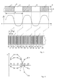
- FIG. 1 shows the schematic representation of a periodically structured scale, the basic periodic course of a physical quantity in the vicinity of the scale and a measurement of the spatial distribution of this physical quantity.
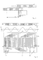
- 2 shows measured values as obtained from the measuring arrangement in the position shown in FIG. 1.
- 3 shows a scale in its starting position and the same scale shifted by a certain distance with respect to the sensor arrangement and serves to explain the position measurement in three stages.
- 4 shows a magnetic scale and a magnetoresistive sensor arrangement suitable for carrying out a length measurement.
- the scale is built up alternately in the longitudinal direction from areas 1 and areas 2.
- the period length p of the scale is given by the sum of the two lengths of the areas 1 and 2.
- the areas 1 and 2 have the effect that in the vicinity of the scale surface a physical quantity E above the location has a periodic course.
- This physical quantity E can be, for example, a magnetic field which is caused by magnetization of regions 1 and 2 in the opposite direction, or a light intensity which arises when passing through a scale with regions 1 and 2 of different light transmission.
- the curve shape of the periodic course of the physical quantity E as a function of the position x is not fixed to specific functions (such as the sine function). All that is required is a continuous course of the function E (x).
- the sensor arrangement which arises from a multiplicity of regions 7, is located in the immediate vicinity of the scale, specifically in such a way that the scale surface and the sensor arrangement surface face each other in parallel. In the figure, the two parts mentioned are shown side by side for the sake of clarity.
- the sensor arrangement is divided into sections 7 of equal length.
- the length of each section corresponds to half the scale period length p / 2.
- the position of the individual sensor elements 10-15, 20-25, 30-35 etc. is completely the same.
- the distance a of all individual sensor elements is the same.
- six individual sensor elements 10-15, 20-25, 30-35 etc. are present in each section 7.
- the starting point of the scale is marked with S.
- the sensor arrangement is shifted by the distance V with respect to this initial value S.
- Each individual sensor element 10-15, 20-25, 30-35 etc. gives an output signal A, e.g. in the form of a voltage or a current, which is proportional to the value of the physical quantity E in place. All individual sensor elements 10-15, 20-25, 30-35 etc. have the same sensitivity.
- the output signals A of the individual sensor elements 10-15 are shown as curve 3 for the position shown in FIG. 1 in FIG. 2.
- the output signals A of the individual sensor elements 20-25 represent curve 4.
- differences in the output signals A of the individual sensor elements are formed, each offset by half a scale period length p / 2, that is, between the individual sensor elements 10 and 20, 11 and 21, 12 and 22, etc. These individual sensor elements thus form the sensor element pairs S 0, S 1, S 3 etc.
- the output signals of the sensor element pairs S 0, S 1, S 3 etc. are shown in FIG. 2 as curve 5.
- Curve 5 has the advantage over curves 3 and 4, which represent the course of the physical quantity in the first and second section 7 of the sensor arrangement, that it is zero-symmetrical with regard to its deflection and that its zero crossing 6 from the location of the first individual sensor element 10 is accurate the offset V is removed. A shift can therefore always be read from the position of the zero crossing.
- the zero crossing 6 of the output signal differences 5 is therefore used to quantitatively determine the magnitude of the shift in the scale relative to the sensor arrangement.
- the zero crossing 6 lies between the sensor pairs S 3 and S 4.
- Fig. 3 it is shown that the scale is shifted from the sensor arrangement by a distance which is more than a whole scale period length p.
- the output signal of the first pair of sensor elements S 0 and the output signal of the pair of sensor elements S 3 offset by a quarter of the period length p are continuously measured during the shift. From these two signals, the number ni of the whole scale periods p is determined using customary incremental counting methods. Forward and backward movements are recognized from the two signals in the known methods.
- the signal averaging is provided by adding further individual sensor elements offset by an entire scale period p over a plurality of period lengths p, but this is not shown in FIG. 1 for the sake of clarity.
- the signal averaging makes the measurement signals much more precise, so that a high degree of interpolation is made possible, which is the prerequisite for a high length resolution.
- FIG. 1 A special embodiment of the method with a magnetic scale and magnetoresistive sensor arrangement is shown in FIG.
- the magnetic track 50 of the scale is drawn smaller than the sensor chip 51 in the width direction. Values in the mm range are provided both for the magnetic track width 50 and for the width of the sensor chip 51.
- the magnetic track 51 has magnetized areas at regular intervals in the positive and negative directions. A periodic magnetic field H (x) is thus present.
- Magnetoresistive layer strips 52 are arranged on the chip 51 as individual sensor elements at a uniform distance. The layer strips 52 all carry the same barber pole structures 56 with the same angle. There are four layer strips 52 per half-scale period.
- the layer strips 52 are connected in series by connecting lines 53.
- the resistance values of the magnetoresistive layer strips 52 are proportional to the magnetic field at their location. In this way, the output signal differences 5 averaged over four scale periods are immediately obtained at the outputs of the voltage dividers 55, without any evaluation circuit being necessary in this case.
- the further processing of the output signal differences 5 to determine the displacement of the scale relative to the sensor arrangement then corresponds to the above.
Landscapes
- Physics & Mathematics (AREA)
- General Physics & Mathematics (AREA)
- Engineering & Computer Science (AREA)
- Signal Processing (AREA)
- Transmission And Conversion Of Sensor Element Output (AREA)
- Testing, Inspecting, Measuring Of Stereoscopic Televisions And Televisions (AREA)
- Optical Transform (AREA)
- Length Measuring Devices With Unspecified Measuring Means (AREA)
- Analysing Materials By The Use Of Radiation (AREA)
- Length Measuring Devices By Optical Means (AREA)
Applications Claiming Priority (2)
| Application Number | Priority Date | Filing Date | Title |
|---|---|---|---|
| DE4237540 | 1992-11-06 | ||
| DE4237540A DE4237540C2 (de) | 1992-11-06 | 1992-11-06 | Verfahren zur hochauflösenden Messung von Linear- und Drehpositionen |
Publications (3)
| Publication Number | Publication Date |
|---|---|
| EP0596535A2 true EP0596535A2 (fr) | 1994-05-11 |
| EP0596535A3 EP0596535A3 (en) | 1994-09-07 |
| EP0596535B1 EP0596535B1 (fr) | 1997-04-16 |
Family
ID=6472294
Family Applications (1)
| Application Number | Title | Priority Date | Filing Date |
|---|---|---|---|
| EP93118089A Expired - Lifetime EP0596535B1 (fr) | 1992-11-06 | 1993-11-08 | Méthode de mesure à haute résolution de positions linéaires et tournantes |
Country Status (5)
| Country | Link |
|---|---|
| EP (1) | EP0596535B1 (fr) |
| AT (1) | ATE151867T1 (fr) |
| DE (2) | DE4237540C2 (fr) |
| DK (1) | DK0596535T3 (fr) |
| ES (1) | ES2099883T3 (fr) |
Cited By (2)
| Publication number | Priority date | Publication date | Assignee | Title |
|---|---|---|---|---|
| WO2002016864A1 (fr) * | 2000-08-22 | 2002-02-28 | Robert Bosch Gmbh | Procede et dispositif de mesure d'angles |
| US6611138B2 (en) | 2000-06-16 | 2003-08-26 | Rexroth Star Gmbh | Inductive measuring device for detecting relative position and/or movement |
Families Citing this family (7)
| Publication number | Priority date | Publication date | Assignee | Title |
|---|---|---|---|---|
| DE19648335C2 (de) * | 1996-11-22 | 2000-05-25 | Daimler Chrysler Ag | Anordnung zur Positionsmessung |
| DE10011289A1 (de) * | 2000-03-08 | 2001-09-20 | Sven Harzbecker | Vorrichtung zur Reinigung der Haut |
| DE10158942B4 (de) * | 2000-12-08 | 2006-05-04 | Micro-Epsilon Messtechnik Gmbh & Co Kg | Vorrichtung und Verfahren zur Detektion der Position eines Messobjekts |
| EP1366849B1 (fr) | 2002-05-27 | 2005-07-27 | Schneeberger Holding AG | Guidage linéaire |
| CN101192412B (zh) * | 2006-12-01 | 2010-10-13 | 上海平信机电制造有限公司 | 粗节距的激光接长录磁载体及其录磁方法 |
| JP6072234B2 (ja) | 2013-04-23 | 2017-02-01 | 三菱電機株式会社 | 磁気式位置検出装置及び磁気式位置検出方法 |
| DE102017121524B4 (de) * | 2017-09-15 | 2019-12-24 | Bogen Electronic Gmbh | Messanordnung |
Citations (1)
| Publication number | Priority date | Publication date | Assignee | Title |
|---|---|---|---|---|
| DE3325353A1 (de) | 1983-07-14 | 1985-01-24 | Honeywell Gmbh | Positionssensor |
Family Cites Families (9)
| Publication number | Priority date | Publication date | Assignee | Title |
|---|---|---|---|---|
| AT339062B (de) * | 1975-11-11 | 1977-09-26 | Rieder Heinz | Verfahren zur langenmessung |
| EP0151002B1 (fr) * | 1984-01-25 | 1991-08-28 | Matsushita Electric Industrial Co., Ltd. | Détecteur magnétique |
| DE3611469A1 (de) * | 1986-04-05 | 1987-10-08 | Bosch Gmbh Robert | Vorrichtung und verfahren zur beruehrungslosen positionsmessung |
| DE3612145A1 (de) * | 1986-04-10 | 1987-10-15 | Ralf Hinkel | Verfahren zur kantendetektierung |
| DD250369A1 (de) * | 1986-06-27 | 1987-10-08 | Werkzeugmasch Forschzent | Einrichtung zur positionsmessung |
| JPH02264818A (ja) * | 1989-04-05 | 1990-10-29 | Seiko Epson Corp | 磁気エンコーダー |
| DE4017954C1 (fr) * | 1990-06-05 | 1991-08-29 | Pav Praezisions-Apparatebau Ag, Vaduz, Li | |
| DE4017898A1 (de) * | 1990-06-02 | 1991-12-05 | Hengstler Gmbh | Optisches abtastsystem fuer dreh- oder linear-impulsgeber |
| DE4203073C2 (de) * | 1992-02-04 | 1994-12-15 | Heidenhain Gmbh Dr Johannes | Positionsmeßeinrichtung |
-
1992
- 1992-11-06 DE DE4237540A patent/DE4237540C2/de not_active Expired - Fee Related
-
1993
- 1993-11-08 DK DK93118089.7T patent/DK0596535T3/da active
- 1993-11-08 DE DE59306176T patent/DE59306176D1/de not_active Expired - Fee Related
- 1993-11-08 ES ES93118089T patent/ES2099883T3/es not_active Expired - Lifetime
- 1993-11-08 EP EP93118089A patent/EP0596535B1/fr not_active Expired - Lifetime
- 1993-11-08 AT AT93118089T patent/ATE151867T1/de not_active IP Right Cessation
Patent Citations (1)
| Publication number | Priority date | Publication date | Assignee | Title |
|---|---|---|---|---|
| DE3325353A1 (de) | 1983-07-14 | 1985-01-24 | Honeywell Gmbh | Positionssensor |
Cited By (5)
| Publication number | Priority date | Publication date | Assignee | Title |
|---|---|---|---|---|
| US6611138B2 (en) | 2000-06-16 | 2003-08-26 | Rexroth Star Gmbh | Inductive measuring device for detecting relative position and/or movement |
| WO2002016864A1 (fr) * | 2000-08-22 | 2002-02-28 | Robert Bosch Gmbh | Procede et dispositif de mesure d'angles |
| AU2001291608B2 (en) * | 2000-08-22 | 2006-02-09 | Robert Bosch Gmbh | Device and method for measuring angles |
| US7170279B2 (en) | 2000-08-22 | 2007-01-30 | Robert Bosch Gmbh | Device and method for measuring angles |
| KR100831454B1 (ko) * | 2000-08-22 | 2008-05-21 | 로베르트 보쉬 게엠베하 | 각도 측정 장치 및 방법 |
Also Published As
| Publication number | Publication date |
|---|---|
| EP0596535A3 (en) | 1994-09-07 |
| ES2099883T3 (es) | 1997-06-01 |
| DE4237540A1 (de) | 1994-05-11 |
| DE59306176D1 (de) | 1997-05-22 |
| EP0596535B1 (fr) | 1997-04-16 |
| ATE151867T1 (de) | 1997-05-15 |
| DE4237540C2 (de) | 1996-02-29 |
| DK0596535T3 (da) | 1997-05-12 |
Similar Documents
| Publication | Publication Date | Title |
|---|---|---|
| DE69032747T2 (de) | Verbesserte Elektrodenstruktur für kapazitive Positionsgeber | |
| EP0093232B1 (fr) | Dispositif magnétique pour déterminer des longueurs ou des angles | |
| DE3784360T2 (de) | Kapazitanztransduktor fuer positionsmessung. | |
| DE69205459T2 (de) | Kombinierter optischer und kapazitiver Apparat zur Messung der absoluten Position. | |
| DE19701925A1 (de) | Vorrichtung zum Messen einer Verschiebung | |
| DE4301971A1 (fr) | ||
| DE2458398A1 (de) | Phasen-messvorrichtung fuer ein bewegtes element | |
| EP0620416B1 (fr) | Système de mesure magnétique | |
| DE3417176A1 (de) | Photoelektrische messeinrichtung | |
| DE19839450A1 (de) | Magnetoresistiver Sensorchip mit mindestens zwei als Halb- oder Vollbrücke ausgebildeten Meßelementen | |
| DE4300028A1 (fr) | ||
| DE112016004941B4 (de) | Positionserfassungsvorrichtung und Bewegungsführungsvorrichtung mit der Positionserfassungsvorrichtung | |
| EP2236990A2 (fr) | Système de mesure de position/trajectoire | |
| DE69515273T2 (de) | Magnetischer Kodierer zum Lesen von Markierungen auf einer dazugehörigen magnetischen Spur | |
| EP0596535B1 (fr) | Méthode de mesure à haute résolution de positions linéaires et tournantes | |
| EP1995566A2 (fr) | Echelle pour un dispositif de mesure de position et dispositif de mesure de position | |
| DE4233331A1 (de) | Anordnung zur Bestimmung von Positionen | |
| DE4438715C1 (de) | Magnetfeldsensorchip | |
| DE2315471A1 (de) | Stellungsgeber fuer elektrische nachfuehreinrichtungen bei registriersystemen | |
| DE10162849B4 (de) | Längenmesssystem, bei dem ein Massstab relativ zur Position von beabstandeten Längensensoren bewegt wird | |
| DE4309881C1 (de) | Anordnung zur Bestimmung der Absolutposition | |
| EP0390725B1 (fr) | Méthode et dispositif pour déterminer la position d'un point de référence par rapport à une règle incrémentale graduée | |
| DE4006789A1 (de) | Optisches abtastsystem fuer rasterteilungen | |
| DE4125865C2 (de) | Längen- oder Winkelmeßeinrichtung | |
| EP0541829A1 (fr) | Dispositif pour générer des signaux périodiques sans harmoniques |
Legal Events
| Date | Code | Title | Description |
|---|---|---|---|
| PUAI | Public reference made under article 153(3) epc to a published international application that has entered the european phase |
Free format text: ORIGINAL CODE: 0009012 |
|
| AK | Designated contracting states |
Kind code of ref document: A2 Designated state(s): AT BE CH DE DK ES FR GB IT LI LU NL SE |
|
| PUAL | Search report despatched |
Free format text: ORIGINAL CODE: 0009013 |
|
| AK | Designated contracting states |
Kind code of ref document: A3 Designated state(s): AT BE CH DE DK ES FR GB IT LI LU NL SE |
|
| RAP1 | Party data changed (applicant data changed or rights of an application transferred) |
Owner name: LEICA MIKROSKOPIE UND SYSTEME GMBH Owner name: MAERZHAEUSER WETZLAR GMBH & CO. KG Owner name: KROEPLIN GMBH Owner name: LUST ANTRIEBSTECHNIK GMBH Owner name: HELMUT HUND GMBH |
|
| RAP3 | Party data changed (applicant data changed or rights of an application transferred) |
Owner name: LEICA MIKROSKOPIE UND SYSTEME GMBH Owner name: MAERZHAEUSER WETZLAR GMBH & CO. KG Owner name: KROEPLIN GMBH Owner name: LUST ANTRIEBSTECHNIK GMBH Owner name: HELMUT HUND GMBH |
|
| 17P | Request for examination filed |
Effective date: 19950111 |
|
| GRAG | Despatch of communication of intention to grant |
Free format text: ORIGINAL CODE: EPIDOS AGRA |
|
| 17Q | First examination report despatched |
Effective date: 19960424 |
|
| GRAH | Despatch of communication of intention to grant a patent |
Free format text: ORIGINAL CODE: EPIDOS IGRA |
|
| GRAH | Despatch of communication of intention to grant a patent |
Free format text: ORIGINAL CODE: EPIDOS IGRA |
|
| GRAA | (expected) grant |
Free format text: ORIGINAL CODE: 0009210 |
|
| AK | Designated contracting states |
Kind code of ref document: B1 Designated state(s): AT BE CH DE DK ES FR GB IT LI LU NL SE |
|
| REF | Corresponds to: |
Ref document number: 151867 Country of ref document: AT Date of ref document: 19970515 Kind code of ref document: T |
|
| ITF | It: translation for a ep patent filed | ||
| REG | Reference to a national code |
Ref country code: CH Ref legal event code: NV Representative=s name: A. BRAUN, BRAUN, HERITIER, ESCHMANN AG PATENTANWAE Ref country code: CH Ref legal event code: EP |
|
| REG | Reference to a national code |
Ref country code: DK Ref legal event code: T3 |
|
| GBT | Gb: translation of ep patent filed (gb section 77(6)(a)/1977) |
Effective date: 19970417 |
|
| REF | Corresponds to: |
Ref document number: 59306176 Country of ref document: DE Date of ref document: 19970522 |
|
| REG | Reference to a national code |
Ref country code: ES Ref legal event code: FG2A Ref document number: 2099883 Country of ref document: ES Kind code of ref document: T3 |
|
| ET | Fr: translation filed | ||
| PLBE | No opposition filed within time limit |
Free format text: ORIGINAL CODE: 0009261 |
|
| STAA | Information on the status of an ep patent application or granted ep patent |
Free format text: STATUS: NO OPPOSITION FILED WITHIN TIME LIMIT |
|
| 26N | No opposition filed | ||
| PGFP | Annual fee paid to national office [announced via postgrant information from national office to epo] |
Ref country code: SE Payment date: 19991018 Year of fee payment: 7 |
|
| PGFP | Annual fee paid to national office [announced via postgrant information from national office to epo] |
Ref country code: ES Payment date: 19991104 Year of fee payment: 7 |
|
| PGFP | Annual fee paid to national office [announced via postgrant information from national office to epo] |
Ref country code: BE Payment date: 19991105 Year of fee payment: 7 |
|
| PGFP | Annual fee paid to national office [announced via postgrant information from national office to epo] |
Ref country code: LU Payment date: 19991111 Year of fee payment: 7 |
|
| PGFP | Annual fee paid to national office [announced via postgrant information from national office to epo] |
Ref country code: DK Payment date: 19991116 Year of fee payment: 7 Ref country code: CH Payment date: 19991116 Year of fee payment: 7 |
|
| PGFP | Annual fee paid to national office [announced via postgrant information from national office to epo] |
Ref country code: AT Payment date: 19991123 Year of fee payment: 7 |
|
| PGFP | Annual fee paid to national office [announced via postgrant information from national office to epo] |
Ref country code: NL Payment date: 19991129 Year of fee payment: 7 |
|
| PG25 | Lapsed in a contracting state [announced via postgrant information from national office to epo] |
Ref country code: LU Free format text: LAPSE BECAUSE OF NON-PAYMENT OF DUE FEES Effective date: 20001108 Ref country code: DK Free format text: LAPSE BECAUSE OF NON-PAYMENT OF DUE FEES Effective date: 20001108 Ref country code: AT Free format text: LAPSE BECAUSE OF NON-PAYMENT OF DUE FEES Effective date: 20001108 |
|
| PG25 | Lapsed in a contracting state [announced via postgrant information from national office to epo] |
Ref country code: ES Free format text: LAPSE BECAUSE OF NON-PAYMENT OF DUE FEES Effective date: 20001109 |
|
| PGFP | Annual fee paid to national office [announced via postgrant information from national office to epo] |
Ref country code: FR Payment date: 20001128 Year of fee payment: 8 |
|
| PG25 | Lapsed in a contracting state [announced via postgrant information from national office to epo] |
Ref country code: SE Free format text: THE PATENT HAS BEEN ANNULLED BY A DECISION OF A NATIONAL AUTHORITY Effective date: 20001129 |
|
| PGFP | Annual fee paid to national office [announced via postgrant information from national office to epo] |
Ref country code: GB Payment date: 20001129 Year of fee payment: 8 |
|
| PG25 | Lapsed in a contracting state [announced via postgrant information from national office to epo] |
Ref country code: LI Free format text: LAPSE BECAUSE OF NON-PAYMENT OF DUE FEES Effective date: 20001130 Ref country code: CH Free format text: LAPSE BECAUSE OF NON-PAYMENT OF DUE FEES Effective date: 20001130 Ref country code: BE Free format text: LAPSE BECAUSE OF NON-PAYMENT OF DUE FEES Effective date: 20001130 |
|
| PGFP | Annual fee paid to national office [announced via postgrant information from national office to epo] |
Ref country code: DE Payment date: 20001215 Year of fee payment: 8 |
|
| BERE | Be: lapsed |
Owner name: MARZHAUSER WETZLAR G.M.B.H. & CO. K.G. Effective date: 20001130 |
|
| PG25 | Lapsed in a contracting state [announced via postgrant information from national office to epo] |
Ref country code: NL Free format text: LAPSE BECAUSE OF NON-PAYMENT OF DUE FEES Effective date: 20010601 |
|
| REG | Reference to a national code |
Ref country code: CH Ref legal event code: PL |
|
| EUG | Se: european patent has lapsed |
Ref document number: 93118089.7 |
|
| REG | Reference to a national code |
Ref country code: DK Ref legal event code: EBP |
|
| NLV4 | Nl: lapsed or anulled due to non-payment of the annual fee |
Effective date: 20010601 |
|
| PG25 | Lapsed in a contracting state [announced via postgrant information from national office to epo] |
Ref country code: GB Free format text: LAPSE BECAUSE OF NON-PAYMENT OF DUE FEES Effective date: 20011108 |
|
| REG | Reference to a national code |
Ref country code: GB Ref legal event code: IF02 |
|
| GBPC | Gb: european patent ceased through non-payment of renewal fee |
Effective date: 20011108 |
|
| PG25 | Lapsed in a contracting state [announced via postgrant information from national office to epo] |
Ref country code: DE Free format text: LAPSE BECAUSE OF NON-PAYMENT OF DUE FEES Effective date: 20020702 |
|
| PG25 | Lapsed in a contracting state [announced via postgrant information from national office to epo] |
Ref country code: FR Free format text: LAPSE BECAUSE OF NON-PAYMENT OF DUE FEES Effective date: 20020730 |
|
| REG | Reference to a national code |
Ref country code: FR Ref legal event code: ST |
|
| REG | Reference to a national code |
Ref country code: FR Ref legal event code: ST |
|
| REG | Reference to a national code |
Ref country code: ES Ref legal event code: FD2A Effective date: 20011214 |
|
| PG25 | Lapsed in a contracting state [announced via postgrant information from national office to epo] |
Ref country code: IT Free format text: LAPSE BECAUSE OF NON-PAYMENT OF DUE FEES;WARNING: LAPSES OF ITALIAN PATENTS WITH EFFECTIVE DATE BEFORE 2007 MAY HAVE OCCURRED AT ANY TIME BEFORE 2007. THE CORRECT EFFECTIVE DATE MAY BE DIFFERENT FROM THE ONE RECORDED. Effective date: 20051108 |