EP0451334A1 - Montre à répétition - Google Patents
Montre à répétition Download PDFInfo
- Publication number
- EP0451334A1 EP0451334A1 EP90122013A EP90122013A EP0451334A1 EP 0451334 A1 EP0451334 A1 EP 0451334A1 EP 90122013 A EP90122013 A EP 90122013A EP 90122013 A EP90122013 A EP 90122013A EP 0451334 A1 EP0451334 A1 EP 0451334A1
- Authority
- EP
- European Patent Office
- Prior art keywords
- axis
- rake
- watch according
- repeater
- movement path
- Prior art date
- Legal status (The legal status is an assumption and is not a legal conclusion. Google has not performed a legal analysis and makes no representation as to the accuracy of the status listed.)
- Granted
Links
- 230000008878 coupling Effects 0.000 claims description 23
- 238000010168 coupling process Methods 0.000 claims description 23
- 238000005859 coupling reaction Methods 0.000 claims description 23
- 238000005096 rolling process Methods 0.000 claims description 22
- 230000007246 mechanism Effects 0.000 claims description 18
- 238000006073 displacement reaction Methods 0.000 claims description 3
- 125000006850 spacer group Chemical group 0.000 claims description 2
- 238000009527 percussion Methods 0.000 claims 3
- 230000002040 relaxant effect Effects 0.000 claims 1
- 238000009434 installation Methods 0.000 description 3
- 238000004519 manufacturing process Methods 0.000 description 1
- 230000002093 peripheral effect Effects 0.000 description 1
- 230000003252 repetitive effect Effects 0.000 description 1
- 239000000523 sample Substances 0.000 description 1
- 230000035939 shock Effects 0.000 description 1
- 210000000707 wrist Anatomy 0.000 description 1
Images


Classifications
-
- G—PHYSICS
- G04—HOROLOGY
- G04B—MECHANICALLY-DRIVEN CLOCKS OR WATCHES; MECHANICAL PARTS OF CLOCKS OR WATCHES IN GENERAL; TIME PIECES USING THE POSITION OF THE SUN, MOON OR STARS
- G04B21/00—Indicating the time by acoustic means
- G04B21/02—Regular striking mechanisms giving the full hour, half hour or quarter hour
- G04B21/12—Reiterating watches or clocks
Definitions
- the invention relates to a repeater watch with a manually tensionable spring, by the relaxation of which an axis can be rotatably driven from a tensioned position into a rest position, with a first rake rotatable from the axis for actuating a first striking mechanism, and with one of the first striking mechanism drivable first hammer, of which a first gong can be struck.
- the object of the invention is therefore to provide a repeater clock of the type mentioned, which is designed in such a way that different tones can be struck, its structure being simple and requiring little installation space.
- This object is achieved in that in a first part of the relaxation movement path of the axis from the clamping position to the rest position the first rake and in the second part of this relaxation movement path a second rake for actuating a second striking mechanism can be rotated by the axis, wherein a second hammer mechanism can be actuated by the second rake, by means of which a second hammer can be driven to strike a second gong spring.
- the rotary drive between the first rake and the axle at the end of the first part of the relaxation movement path of the axle can be uncoupled by a first coupling device and the rotary drive between the second rake and the axle at the beginning of the second part of the relaxation movement path of the axle can be engaged by a second coupling device.
- the rotary drive between the first rake and the axis preferably has a component which is freely rotatably mounted on the axis and drives the first rake and which can be connected in a rotationally fixed manner to the axis by the first coupling device.
- a simply constructed and easy-to-operate coupling is formed in that the first coupling device has a detent which can be latched radially into a recess on the cylindrical lateral surface of the axis, producing a rotationally fixed connection, and radially at the end of the second part of the relaxation movement path of the axis Recess is movably drivable, on the first component, which is freely rotatable on the axis, a decoupling lever which is pivotable about a pivot axis parallel to the axis is mounted, at one free end of which the catch is arranged and which has a decoupling finger projecting approximately radially outwards, which can be struck against a stop at the end of the first part of the relaxation movement path and its catch can be pivoted out of the recess in the axis.
- the first component of the is a disc-shaped first rake, which has teeth on its radially circumferential edge region, through which a first creator of the first striking mechanism can be pivotably driven.
- the rotary drive can have, between the second rake and the axle, a component which is freely rotatably mounted on the axle and drives the second rake and which can be connected to the axle in a rotationally fixed manner by the second coupling device.
- the second coupling device is a clamping direction lock, by means of which a rotationally fixed connection between the axle and the second component during the relaxation movement path from the beginning of its second part to the rest position can be produced.
- the lock of the clamping direction lock can be a rolling element in a simple manner.
- the rolling element is arranged in a locking recess which is designed to be radially open to the outside in the area of the cylindrical circumferential surface of the axis covered by the second component and whose depth increases in the direction of relaxation of the axis from a slightly smaller dimension than the diameter of the rolling element , the axis and the second component are safely coupled in one direction of rotation of the axis at the desired time and the axis is also freely rotated in the other direction of rotation.
- the locking recess can be formed on a circular disc-shaped, coaxially rotatably arranged driver, the cylindrical outer surface of which forms a slide bearing on which the second component is rotatably supported with a central bore, on the latter cylindrical inner wall of the rolling element axis and second component can be brought into contact in a rotationally fixed connection.
- the rolling element can be spaced apart from the cylindrical inner wall of the central one by means of a distance guide in the first part of the relaxation movement path of the axis Be borehole.
- the spacing guide can have a slideway that extends concentrically to the axis along the first part of the relaxation movement path of the axis.
- the rolling element is arranged with an end projecting parallel to the axis from the locking recess on a sliding piece which is mounted so as to be displaceable in a plane perpendicular to the axis and whose displacement is limited radially outward in the region of the first part of the relaxation movement path of the axis by the slideway is along which a sliding surface of the slider is slidably guided, so after leaving the first part of the relaxation movement path, the slider with the rolling element can move radially outwards and the rolling element can move into the area of the locking recess in which it is between the cylindrical inner wall the hole of the second component and the bottom of the locking recess is clamped and couples these two parts together in a rotationally fixed manner. Contribution to the smooth operation is made if the sliding surface of the sliding piece has a curvature corresponding to the curvature of the slide.
- the second component driving the second rake can be a drive gearwheel which engages in a tooth sector of the second rake which can be pivoted about a pivot axis.
- the second rake preferably has a row of teeth arranged concentrically to the swivel axis, through the teeth of a second creator of the second striking mechanism is pivotally driven.
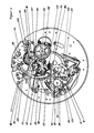
- the repeater watch shown has an elevator lever 1, which is activated by manual actuation of its actuating cam 2 can be pivoted counterclockwise about a pivot axis 3 until it comes into contact with an hourly scale 5 with a stop pin 4.
- the hourly scale 5 is rotatably driven about an axis 6 at one revolution per twelve hours and has twelve stages on its radially circumferential circumferential surface which are distributed evenly and are arranged in a spiral, increasing in height.
- the elevator lever 1 can thus be pivoted more or less about its pivot axis 3.
- an elevator drive wheel 8 which is arranged in a rotationally fixed manner on an axis 9, can be rotatably driven via a tooth sector 7 arranged concentrically to the pivot axis 3 on the elevator lever 1.
- a tension spring 10 which spirally surrounds the axis 9 is fastened with its inner end to the axis 9, while it is fixedly arranged with its outer end to a rotationally fixed barrel concentrically surrounding the axis 9.
- a circular disk-shaped hour / quarter hour rake 11 is also freely rotatably mounted on the axis 9 and can be connected in a rotationally fixed manner to the axis by means of a first coupling device.
- the hour / quarter-hour rake 11 has a row of twelve hour teeth 12, a first row of three quarter-hour teeth 13 and a second row of three quarter-hour teeth 14 in a clockwise direction one after the other.
- This rotary movement of the hour / quarter hour rake 11 takes place after the tensioning of the tension spring 10 has been carried out by manually pivoting the elevator lever 1, by means of the tension spring 10 which relaxes again.
- an hour hammer lever 19 carrying an hour hammer 18 at its free end can be pivotably driven via a pivotable intermediate lever 17 in such a way that the hour hammer 18 is moved away from an hourly tone spring 21 against the force of the spring 20.
- the hour hammer 18 is then moved by the spring 20 with momentum against the hour tone spring 21 and a tone is generated by striking.
- the spring 25 moves the quarter-hour hammer 24 with momentum against the quarter-hour tone spring 26 and generates a tone by striking which has a different pitch than the hour spring 21.
- the hour teeth 12 and the quarter hour teeth 13 have the same radial extension compared to the quarter hour teeth 14.
- the hour creator 15 can be pivotally driven both by the hour teeth 12 and by the quarter hour teeth 13, while the quarter hour creator 16 arranged at a somewhat greater radial distance from the hour / quarter hour rake 11 can only be driven by the quarter hour teeth 14.
- the distance from the hour creator 15 and the quarter hour creator 16 in the circumferential direction is such that double strikes are carried out when the quarter hours are struck.
- the quarter-hour scoop 16 is pivoted by a quarter-hour tooth 14 and, shortly thereafter, the hour-scoop 15 is pivoted by a quarter-hour tooth 13.
- the number of hourly strikes is determined by the angle of rotation by which the axis 9 is rotated by the pivoting movement of the elevator lever 1 and thus by the position of the hourly scale 5.
- the first coupling device and a pivotable quarter distributor 27 determine the pivot angle at which the quarter-hour teeth 13 and 14 can drive the hour creator 15 and the quarter hour creator 16, respectively.
- the first coupling device has a catch 28 which is arranged on a decoupling lever 29 which is pivotably mounted on the hour / quarter hour rake 11 about a pivot axis 30 parallel to the axis 9 in such a way that the catch 28 is approximately radial under the action of a spring 31 can engage a recess 31 of a driving disk 32 which is open radially outwards and can produce a rotationally fixed connection.
- the drive plate 32 is coaxially fixed to the axis 9, so that a non-rotatable connection between hour / quarter hour rake 11 and axis 9 can be produced by means of the catch 28 which engages in the recess 31.
- the decoupling lever 29 has an approximately radially protruding decoupling finger 33 which, when the hourly / quarter-hour rake 11 is driven in a clockwise direction, after a certain rotational path into a hook recess adjoining the rotational path determining the hourly shocks 34 of the quarter distributor 27 can intervene.
- the quarter distributor 27 can then only be pivoted up to the abutment against a stop 35 and ends the non-rotatable coupling between the axis 9 and hours / quarter hour rake 11 by pivoting the catch 28 out of the recess 31 by the decoupler finger 33 held by the quarter distributor 27 becomes.
- the quarter distributor 27 has four hook recesses 34 arranged approximately one after the other in the circumferential direction of the hour / quarter hour calculator 11, wherein in each case one hook recess 34 is assigned to a quarter of an hour.
- the counterclockwise first hook recess 34 corresponds to the first quarter of an hour and the counterclockwise last hook recess 34 corresponds to the last quarter of an hour.
- a hook recess 34 comes into the peripheral area of the decoupler finger 33 so that it can hook there.
- the pivot position of the quarter distributor 27 is determined by a button 36, which is arranged on a probe arm 37 of the quarter distributor 27 and scans a quarter hour scale 38.
- the quarter-hour scale 38 is rotatably driven about an axis 39 by the clockwork at one revolution per three hours and has three graduations 40 each having four levels, evenly distributed on its circumference.
- the quarter distributor 27 can pivot more or less and bring the hook recess 34 associated with the demoted quarter hour level into the area of the decoupler finger 33.
- a circular disk-shaped driver 42 is arranged in a rotationally fixed manner, the radially rotating one cylindrical outer surface forms a slide bearing on which a drive gear 41 with a central bore 47 is freely rotatable.
- the driver 42 has on its cylindrical outer surface a radially outwardly open locking recess 43.
- This locking recess 43 is designed step-like with different depths, the first step 44 in the counterclockwise direction having a radially outwardly slightly increasing depth in the clockwise direction.
- the depth of the second step 45 is significantly greater than that of the first step, the second step 45 forming an approximately circular trough.
- a roller-like rolling element 46 projects axially into the locking recess 43 axially to the axis 9.
- the diameter of the rolling element 46 corresponds to the shape of the trough of the second step 45 and is slightly larger than the depth of the first step 44.
- the rolling element 46 is with its end protruding upward from the locking recess 43 in a bore 48 a disc-like slider 49 is arranged, which is slidably mounted on the surface of the driver 42 in the plane perpendicular to the axis 9.
- the slider 49 On its radially outward side, the slider 49 has a circular sector-like sliding surface 50 which can slide along a corresponding slideway 51 of a spacer guide 52.
- the slideway 51 extends concentrically to the axis 9 by a region which corresponds to the third part of the angle of rotation about which the axis 9 is rotated by the pivoting movement of the elevator lever 1.
- the hour / quarter hour calculator 11 is driven and thus the hours and the quarter hours are struck.
- the drive gear 41 engages in a toothed sector 53 of a minute rake 54 and pivots it about a pivot axis 55.
- the minute rake 54 is made of a Position pivotable, which is determined by a button 56, which comes to rest on a minute scale 57.
- the minute series 57 has a row of teeth 58 with fourteen tooth gaps, each tooth gap representing a minute position.
- a row of teeth with fourteen minute teeth 60 is arranged concentrically to the pivot axis 55 on the minute rake 54, by means of which a minute scraper 61 can be pivotably driven.
- the minute scraper 61 is pivotable about the same axis as the quarter-hour scoop 16 and also drives the intermediate lever 22, the quarter-hour hammer lever 23 and the quarter-hour lever 24.
Landscapes
- Physics & Mathematics (AREA)
- General Physics & Mathematics (AREA)
- Measurement Of Unknown Time Intervals (AREA)
- Toys (AREA)
- Electromechanical Clocks (AREA)
Applications Claiming Priority (2)
| Application Number | Priority Date | Filing Date | Title |
|---|---|---|---|
| DE4012058 | 1990-04-13 | ||
| DE4012058A DE4012058A1 (de) | 1990-04-13 | 1990-04-13 | Repetieruhr |
Publications (2)
| Publication Number | Publication Date |
|---|---|
| EP0451334A1 true EP0451334A1 (fr) | 1991-10-16 |
| EP0451334B1 EP0451334B1 (fr) | 1994-03-16 |
Family
ID=6404405
Family Applications (1)
| Application Number | Title | Priority Date | Filing Date |
|---|---|---|---|
| EP90122013A Expired - Lifetime EP0451334B1 (fr) | 1990-04-13 | 1990-11-17 | Montre à répétition |
Country Status (2)
| Country | Link |
|---|---|
| EP (1) | EP0451334B1 (fr) |
| DE (2) | DE4012058A1 (fr) |
Cited By (2)
| Publication number | Priority date | Publication date | Assignee | Title |
|---|---|---|---|---|
| EP2498143A1 (fr) * | 2011-03-08 | 2012-09-12 | Montres Breguet SA | Mécanisme d'isolement entre mécanismes horlogers de déclenchement de différents signaux sonores |
| CN106842886A (zh) * | 2015-10-21 | 2017-06-13 | 布朗潘有限公司 | 用于机械手表的可调节小睡定时器 |
Citations (4)
| Publication number | Priority date | Publication date | Assignee | Title |
|---|---|---|---|---|
| CH7905A (fr) * | 1894-01-27 | 1894-07-31 | Le Coultre & Cie | Mécanisme de répétition à minutes simplifié et monté sur un mouvement de montre simple |
| CH9962A (fr) * | 1895-03-29 | 1895-10-31 | Aubert George | Mécanisme réglant la sonnerie des quarts et minutes dans les montres à répétition de façon à supprimer les silences de longueur variable qui séparent la sonnerie des heures de celle des quarts ou minutes |
| CH81475A (de) * | 1918-11-20 | 1919-06-16 | Hermann Scherzinger | Repetiervorrichtung an Uhren |
| CH344955A (fr) * | 1958-10-17 | 1960-02-29 | D Horlogerie Angelus Stolz Fre | Montre-bracelet à répétition |
-
1990
- 1990-04-13 DE DE4012058A patent/DE4012058A1/de not_active Ceased
- 1990-11-17 EP EP90122013A patent/EP0451334B1/fr not_active Expired - Lifetime
- 1990-11-17 DE DE90122013T patent/DE59005026D1/de not_active Expired - Fee Related
Patent Citations (4)
| Publication number | Priority date | Publication date | Assignee | Title |
|---|---|---|---|---|
| CH7905A (fr) * | 1894-01-27 | 1894-07-31 | Le Coultre & Cie | Mécanisme de répétition à minutes simplifié et monté sur un mouvement de montre simple |
| CH9962A (fr) * | 1895-03-29 | 1895-10-31 | Aubert George | Mécanisme réglant la sonnerie des quarts et minutes dans les montres à répétition de façon à supprimer les silences de longueur variable qui séparent la sonnerie des heures de celle des quarts ou minutes |
| CH81475A (de) * | 1918-11-20 | 1919-06-16 | Hermann Scherzinger | Repetiervorrichtung an Uhren |
| CH344955A (fr) * | 1958-10-17 | 1960-02-29 | D Horlogerie Angelus Stolz Fre | Montre-bracelet à répétition |
Cited By (7)
| Publication number | Priority date | Publication date | Assignee | Title |
|---|---|---|---|---|
| EP2498143A1 (fr) * | 2011-03-08 | 2012-09-12 | Montres Breguet SA | Mécanisme d'isolement entre mécanismes horlogers de déclenchement de différents signaux sonores |
| CN102681428A (zh) * | 2011-03-08 | 2012-09-19 | 蒙特雷布勒盖股份有限公司 | 用于隔离释放各种声音信号的钟表机构的隔离机构 |
| JP2012189593A (ja) * | 2011-03-08 | 2012-10-04 | Montres Breguet Sa | さまざまな音響信号を発する時計機構を絶縁するための機構 |
| CN102681428B (zh) * | 2011-03-08 | 2014-08-13 | 蒙特雷布勒盖股份有限公司 | 用于隔离释放各种声音信号的钟表机构的隔离机构 |
| US8873347B2 (en) | 2011-03-08 | 2014-10-28 | Montres Breguet S.A. | Mechanism for isolating timepiece mechanisms which release various acoustic signals |
| CN106842886A (zh) * | 2015-10-21 | 2017-06-13 | 布朗潘有限公司 | 用于机械手表的可调节小睡定时器 |
| CN106842886B (zh) * | 2015-10-21 | 2019-05-14 | 布朗潘有限公司 | 用于机械手表的可调节小睡定时器 |
Also Published As
| Publication number | Publication date |
|---|---|
| DE59005026D1 (de) | 1994-04-28 |
| EP0451334B1 (fr) | 1994-03-16 |
| DE4012058A1 (de) | 1991-10-17 |
Similar Documents
| Publication | Publication Date | Title |
|---|---|---|
| DE60205763T2 (de) | Timepiece provided with striking mechanism | |
| DE68906041T2 (de) | Uhr. | |
| DE2725514C3 (de) | Uhrwerk fur eine Kalenderuhr | |
| EP0451334B1 (fr) | Montre à répétition | |
| DE2709824C3 (de) | Steuermechanismus fur mechanisches Uhrwerk | |
| DE3148853C2 (de) | Schlagwerksuhr mit Vorrichtung zum zeitweisen Verhindern des Gong- oder Glockenschlages | |
| CH288209A (de) | Uhrwerk mit einer ein arretierbares Aufzuggewicht aufweisenden automatischen Aufzugvorrichtung. | |
| EP1367463B1 (fr) | Montre | |
| EP0451337B1 (fr) | Montre à répétition | |
| DE937776C (de) | Einstellvorrichtung fuer ein Waehlergetriebe eines Drucktelegraphen | |
| DE1523767A1 (de) | Weckeruhr | |
| DE102019130516B3 (de) | Weckerauslösevorrichtung | |
| EP0451336B1 (fr) | Dispositif de remontage à ressort | |
| DE844750C (de) | Waehler fuer Fernmeldeanlagen | |
| DE2451407A1 (de) | Schaltvorrichtung | |
| DE114329C (fr) | ||
| DE937715C (de) | Kurzzeitschaltuhr | |
| DE457465C (de) | Kurzzeitmesser mit Alarmvorrichtung | |
| DE2301988C3 (de) | Zeitgebermechanismus für eine Uhr o.dgl | |
| EP0451338A1 (fr) | Montre à répétition | |
| DE309889C (fr) | ||
| DE1625003C (de) | Schalteinrichtung für ein Zahnräder-Wechselgetriebe kleiner Leistung, insbesondere für das Getriebe eines Zeitrelais | |
| DE576311C (de) | Uhrschlagwerk mit Selbstregelung | |
| AT55327B (de) | Taktschlaguhr. | |
| WO2024032926A1 (fr) | Pièce d'horlogerie ayant une répétition aux quarts et une répétition aux heures |
Legal Events
| Date | Code | Title | Description |
|---|---|---|---|
| PUAI | Public reference made under article 153(3) epc to a published international application that has entered the european phase |
Free format text: ORIGINAL CODE: 0009012 |
|
| 17P | Request for examination filed |
Effective date: 19910711 |
|
| AK | Designated contracting states |
Kind code of ref document: A1 Designated state(s): CH DE FR IT LI |
|
| 17Q | First examination report despatched |
Effective date: 19920909 |
|
| GRAA | (expected) grant |
Free format text: ORIGINAL CODE: 0009210 |
|
| AK | Designated contracting states |
Kind code of ref document: B1 Designated state(s): CH DE FR IT LI |
|
| PG25 | Lapsed in a contracting state [announced via postgrant information from national office to epo] |
Ref country code: IT Free format text: LAPSE BECAUSE OF FAILURE TO SUBMIT A TRANSLATION OF THE DESCRIPTION OR TO PAY THE FEE WITHIN THE PRESCRIBED TIME-LIMIT;WARNING: LAPSES OF ITALIAN PATENTS WITH EFFECTIVE DATE BEFORE 2007 MAY HAVE OCCURRED AT ANY TIME BEFORE 2007. THE CORRECT EFFECTIVE DATE MAY BE DIFFERENT FROM THE ONE RECORDED. Effective date: 19940316 Ref country code: FR Effective date: 19940316 |
|
| REF | Corresponds to: |
Ref document number: 59005026 Country of ref document: DE Date of ref document: 19940428 |
|
| EN | Fr: translation not filed | ||
| PLBE | No opposition filed within time limit |
Free format text: ORIGINAL CODE: 0009261 |
|
| STAA | Information on the status of an ep patent application or granted ep patent |
Free format text: STATUS: NO OPPOSITION FILED WITHIN TIME LIMIT |
|
| 26N | No opposition filed | ||
| PG25 | Lapsed in a contracting state [announced via postgrant information from national office to epo] |
Ref country code: DE Effective date: 19950801 |
|
| PGFP | Annual fee paid to national office [announced via postgrant information from national office to epo] |
Ref country code: CH Payment date: 19981023 Year of fee payment: 9 |
|
| PG25 | Lapsed in a contracting state [announced via postgrant information from national office to epo] |
Ref country code: CH Free format text: LAPSE BECAUSE OF NON-PAYMENT OF DUE FEES Effective date: 19991130 Ref country code: LI Free format text: LAPSE BECAUSE OF NON-PAYMENT OF DUE FEES Effective date: 19991130 |
|
| REG | Reference to a national code |
Ref country code: CH Ref legal event code: PL |