EP0451338A1 - Montre à répétition - Google Patents
Montre à répétition Download PDFInfo
- Publication number
- EP0451338A1 EP0451338A1 EP90122017A EP90122017A EP0451338A1 EP 0451338 A1 EP0451338 A1 EP 0451338A1 EP 90122017 A EP90122017 A EP 90122017A EP 90122017 A EP90122017 A EP 90122017A EP 0451338 A1 EP0451338 A1 EP 0451338A1
- Authority
- EP
- European Patent Office
- Prior art keywords
- hour
- quarter
- teeth
- spring
- row
- Prior art date
- Legal status (The legal status is an assumption and is not a legal conclusion. Google has not performed a legal analysis and makes no representation as to the accuracy of the status listed.)
- Granted
Links
Images


Classifications
-
- G—PHYSICS
- G04—HOROLOGY
- G04B—MECHANICALLY-DRIVEN CLOCKS OR WATCHES; MECHANICAL PARTS OF CLOCKS OR WATCHES IN GENERAL; TIME PIECES USING THE POSITION OF THE SUN, MOON OR STARS
- G04B21/00—Indicating the time by acoustic means
- G04B21/02—Regular striking mechanisms giving the full hour, half hour or quarter hour
- G04B21/12—Reiterating watches or clocks
Definitions
- the invention relates to a repeater watch with a clockwork and a spring that can be tensioned manually depending on the current hour position of the clockwork, with an hour / quarter-hour rake that can be rotatably driven by the relaxing spring and of which an hour creator of an hourly striking mechanism and a quarter-hour creator of a quarter-hourly striking mechanism an hour hammer against an hour spring and a quarter hour hammer against a quarter hour spring can be pivotally driven.
- the object of the invention is therefore to create a repeater clock of the type mentioned, the repeater mechanism has a particularly small size.
- the circular disk-shaped hour / quarter-hour rake is freely rotatably mounted on a spring axis on which the spring arranged at one end is fixed at its other end that the spring axis the spring exciting manually in one direction of rotation an angular position corresponding to the current hour position of the clockwork and can be rotatably driven by the relaxing spring in the other direction of rotation, with a coupling device which, when the spring core axis is driven in the spring tensioning direction, can be rotatably connected to the spring core axis and hourly / quarter-hour rake, and which when the spring core axis is driven in Spring release direction can be disengaged after overcoming an angle of rotation corresponding to the current hour and quarter hour position of the clockwork.
- the teeth of the rows of teeth are preferably designed to protrude radially.
- a particularly small size is achieved with a simple construction if the row of teeth of the hour teeth, the second row of teeth of the quarter hour teeth and the first row of teeth of the quarter hour teeth are arranged one behind the other, and in the case of spring-driven hour / quarter hour rakes after driving the Hour creator through the hours teeth alternately, the hour creator through the quarter-hour teeth of the second row of teeth and the quarter-hour creator through the quarter-hour teeth of the first row of teeth can be pivoted, since many components are then arranged in one plane, which leads to a low overall height.
- the quarter-hour teeth of the first row of teeth preferably protrude radially further than the quarter-hour teeth of the second row of teeth and the hour teeth, the hour creator and quarter hour creator being arranged in the circumferential direction at a distance from one another which is half a tooth distance smaller or greater than the second row of teeth of the quarter hour teeth .
- the coupling device determining the number of quarter-hour beats has a simple structure, if the coupling device has a decoupling lever which is pivotably mounted on the hourly / quarter-hour rake about a pivot axis parallel to the longitudinal axis of the spring core axis and which, when spring-loaded, can be latched approximately radially into a corresponding recess in the spring core axis and pivoted out of the recess by means of a hook-like quarter distributor.
- the decoupling lever can have an approximately radially protruding decoupling finger which, after overcoming an angle of rotation corresponding to the current hours of the clockwork of the hour / quarter hour calculation driven by the relaxing spring, can be engaged in a hook opening of the quarter distributor corresponding to the respective quarter hour and by overcoming another by the current quarter-hour determined angle of rotation, the further rotary movement of the hourly / quarter-hour arithmetic blocking the latching arm can be acted upon by disengaging the recess.
- the quarter distributor is a lever which can be pivoted about an axis parallel to the longitudinal axis of the spring core axis and which, at its one free end, four successively arranged in the circumferential direction of the hour / quarter hour calculation, each one quarter of an hour has associated hook openings, the quarter distributor being pivotally adjustable into a position in which the hook opening assigned to the current quarter hour protrudes into the circumferential area of the decoupler finger, and wherein the swivel path of the in the hook opening engaging decoupler finger pivotally moved quarter distributor in the disengaged position of the locking arm is limited by a stop.
- the quarter distributor can be pivoted counter to the pivoting movement to the stop until a pushbutton arranged on it can be pivoted on a quarter hour scale which can be driven by the clockwork and which has four or a multiple of four stages in a spiral in the circumferential direction, with system of the button on a step the hook opening corresponding to this step is pivoted into the circulation area of the disengaging finger.
- the quarter distributor is preferably spring-loaded in order to rest the button on the quarter-hour scale.
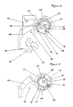
- the repeater watch shown has an elevator lever 1 which cannot be seen in FIG. 1 and which is arranged pivotably about an axis 2. By manually actuating a cam 3, the elevator lever 1 can be pivoted until an abutment pin 4 arranged thereon abuts against an hourly scale 5.
- the hourly scale 5 is formed spirally with twelve stages and is rotatably driven by a clockwork, not shown, with one revolution in 12 hours. According to the steps, the elevator lever 1 can thus be pivoted more or less.
- the elevator drive wheel 7 is fixedly arranged on a rotatably mounted spring core axis 8.
- Also firmly connected to the spring core axis 8 is one end of a tension spring 9 which spirally surrounds the spring core axis 8 and the other end of which is attached to a fixed barrel 10.
- an hourly / quarter-hour rake 11 is freely rotatably mounted on the spring core axis 8, next to which, in turn, a circular drive plate 12 is arranged in a rotationally fixed manner on the spring core axis 8, which has a recess 13 which is open radially outwards.
- a decoupling lever 14 is pivotally mounted in the same plane as the drive plate 12, the one free lever arm of which forms a latching arm 15 which can be latched approximately radially into the recess 13 and thus rotates the hour / quarter-hour rake 11 in a rotationally fixed manner with the Drive plate 12 and the spring core axis 8 connects.
- the decoupler lever 14 has an approximately radially protruding decoupler finger 16, by means of which the decoupler lever 14 can be pivoted in such a way that the locking arm 15 pivots out of the recess 13.
- the decoupling lever 14 is acted upon with its latching arm 15 against the radially circumferential cylindrical outer surface of the driving plate 12 and thus latches with the latching arm 15 into the recess 13 when the latching arm 15 and recess 13 overlap reach.
- a row of teeth with twelve teeth 18, a second row of teeth with three quarter-teeth 19 and a first row of teeth with three quarter-hours 20 is arranged in a clockwise direction on the radially circumferential surface of the hour / quarter rake 11 with radially protruding teeth.
- the hour teeth 18 and the quarter hour teeth 19 protrude radially equally far, while the quarter hour teeth 20 protrude somewhat further radially than the other teeth.
- the hour teeth 18 and quarter hour teeth 19 can be used by a driver nose 21 and an hour creator 22 and the quarter hour teeth 20 a driver nose 23 one Swivel quarter-hour scoop 24 against a spring force.
- an intermediate lever 25 can be pivoted about an axis 26, which in turn engages a pivotable hour hammer lever 27 and lifts it against an hourly tone spring 30 with its hour hammer 29 against the force of a spring 28.
- the quarter-hour scraper 24 is pivoted by a quarter-hour tooth 20, which in turn transmits this movement via an intermediate lever 32 pivotable about the axis 31 to a pivotable quarter-hour hammer lever 33, at the end of which a quarter-hour hammer 34 is arranged.
- This is lifted by a quarter-hour spring 35 against the force of a spring 36.
- the quarter-hour hammer 34 strikes the quarter-hour spring 35, which produces a higher tone than the hourly spring 30.
- a minute creator 37 is also mounted on the axis 31, which can be pivoted by a minute rake 38 with fourteen minute teeth 39 and which also drives the quarter-hour hammer 34 via the intermediate lever 32 and the quarter-hour hammer 33 to strike the quarter-hour spring 35.
- Hour scoop 22 and quarter hour scoop 24 are arranged in the circumferential direction one behind the other with a distance that is half a tooth distance larger than the row of teeth of quarter hour teeth 19.
- the distance between quarter hour scoop 24 and hour / quarter hour rake 11 is so great that it does not differ from the hour teeth 18 and the quarter-hour teeth 19 but can only be driven pivotably by the quarter-hour teeth 20.
- a quarter distributor 40 designed as a two-armed lever, which is arranged pivotably about an axis 41 parallel to the longitudinal axis of the spring core axis 8.
- the quarter distributor 40 has four consecutively arranged approximately in the circumferential direction of the hour / quarter hour calculator 11 hook openings 42 associated with a quarter of an hour.
- the quarter distributor 40 can be adjusted so that when the hour / quarter hour calculator 11 is turned counterclockwise, the decoupler finger 16 either moves into the first, second, third or fourth hook recess 41, and with further rotation the quarter distributor 40 moves clockwise takes until it comes to rest against a stop 43.
- the decoupler lever 14 located in one of the hook openings 42 with its decoupler finger 16 is pivoted in such a way that it is moved radially outward from the recess 13 with its locking arm 15.
- the position shown in FIG. 6 after the repeater has expired is also the rest position in which the quarter distributor 40 is held against the force of a spring 44 acting on it in abutment against the stop 43.
- the spring core axis 8 rotates clockwise. If the recess 13 and the latch arm 15 overlap, it engages in the recess 13 and the hourly / quarter-hour rake 11 is taken along in a clockwise direction.
- the quarter distributor 40 can pivot counterclockwise by the force applied to the spring 44 until it comes to rest on a step of a quarter-hour scale 46 with a button 45 formed at the free end of its lever opposite the hook openings 42.
- the quarter-hour scale 46 is designed to be driven in a spiral manner about an axis 47 and has three seasons 48, each with four levels of spiraling increasing depth. The drive works through the clockwork with one turn in three hours.
- the button 45 comes to rest on the deepest step, which means that the last hook opening 42 in the direction of movement to the stop 43 is positioned for receiving the decoupler finger 16.
- the button 45 can rest on the highest step and position the first hook opening 42 in the direction of movement to the stop 43 for receiving the decoupler finger 16.
- the second and third hook openings 42 are accordingly positioned when the button 45 is placed on the second or third stage.
- the button 45 Since the button 45 is pivoted out of the area of the quarter-hour relay 46 in the rest position of the revolving mechanism, it can be driven unhindered by the clockwork and rotate.
Landscapes
- Physics & Mathematics (AREA)
- General Physics & Mathematics (AREA)
- Electromechanical Clocks (AREA)
- Measurement Of Unknown Time Intervals (AREA)
Applications Claiming Priority (2)
| Application Number | Priority Date | Filing Date | Title |
|---|---|---|---|
| DE4012028A DE4012028A1 (de) | 1990-04-13 | 1990-04-13 | Repetieruhr |
| DE4012028 | 1990-04-13 |
Publications (2)
| Publication Number | Publication Date |
|---|---|
| EP0451338A1 true EP0451338A1 (fr) | 1991-10-16 |
| EP0451338B1 EP0451338B1 (fr) | 1993-12-15 |
Family
ID=6404381
Family Applications (1)
| Application Number | Title | Priority Date | Filing Date |
|---|---|---|---|
| EP90122017A Expired - Lifetime EP0451338B1 (fr) | 1990-04-13 | 1990-11-17 | Montre à répétition |
Country Status (2)
| Country | Link |
|---|---|
| EP (1) | EP0451338B1 (fr) |
| DE (2) | DE4012028A1 (fr) |
Citations (7)
| Publication number | Priority date | Publication date | Assignee | Title |
|---|---|---|---|---|
| US383260A (en) * | 1888-05-22 | walzee | ||
| CH6099A (fr) * | 1893-01-04 | 1893-08-15 | Mathey Tissot E | Montre à répétition à quarts, perfectionnée |
| CH7894A (fr) * | 1894-01-18 | 1894-08-15 | Z Pantillon | Montre à grande sonnerie et répétition |
| CH9962A (fr) * | 1895-03-29 | 1895-10-31 | Aubert George | Mécanisme réglant la sonnerie des quarts et minutes dans les montres à répétition de façon à supprimer les silences de longueur variable qui séparent la sonnerie des heures de celle des quarts ou minutes |
| CH14007A (fr) * | 1897-04-05 | 1897-09-30 | Freres Reymond | Mécanisme simplifié de répétition à minutes |
| CH16382A (fr) * | 1898-04-30 | 1898-11-30 | Marchand & Sandoz | Mécanisme perfectionné de montre à répétition |
| DE412846C (de) * | 1925-04-28 | Kramer Carl | Wiederholungsschlagwerk fuer Uhren, dessen Ablauf durch das Gehwerk geregelt wird |
-
1990
- 1990-04-13 DE DE4012028A patent/DE4012028A1/de not_active Ceased
- 1990-11-17 DE DE90122017T patent/DE59003898D1/de not_active Expired - Fee Related
- 1990-11-17 EP EP90122017A patent/EP0451338B1/fr not_active Expired - Lifetime
Patent Citations (7)
| Publication number | Priority date | Publication date | Assignee | Title |
|---|---|---|---|---|
| US383260A (en) * | 1888-05-22 | walzee | ||
| DE412846C (de) * | 1925-04-28 | Kramer Carl | Wiederholungsschlagwerk fuer Uhren, dessen Ablauf durch das Gehwerk geregelt wird | |
| CH6099A (fr) * | 1893-01-04 | 1893-08-15 | Mathey Tissot E | Montre à répétition à quarts, perfectionnée |
| CH7894A (fr) * | 1894-01-18 | 1894-08-15 | Z Pantillon | Montre à grande sonnerie et répétition |
| CH9962A (fr) * | 1895-03-29 | 1895-10-31 | Aubert George | Mécanisme réglant la sonnerie des quarts et minutes dans les montres à répétition de façon à supprimer les silences de longueur variable qui séparent la sonnerie des heures de celle des quarts ou minutes |
| CH14007A (fr) * | 1897-04-05 | 1897-09-30 | Freres Reymond | Mécanisme simplifié de répétition à minutes |
| CH16382A (fr) * | 1898-04-30 | 1898-11-30 | Marchand & Sandoz | Mécanisme perfectionné de montre à répétition |
Also Published As
| Publication number | Publication date |
|---|---|
| DE4012028A1 (de) | 1991-10-17 |
| EP0451338B1 (fr) | 1993-12-15 |
| DE59003898D1 (de) | 1994-02-03 |
Similar Documents
| Publication | Publication Date | Title |
|---|---|---|
| DE60205763T2 (de) | Timepiece provided with striking mechanism | |
| EP3070543A1 (fr) | Carillon à répétition doté d'un verrouillage de déclenchement intégré | |
| DE2929091A1 (de) | Schlagwerk fuer eine uhr | |
| DE3323420C2 (de) | Schlagwerksuhr mit Vorrichtung zum Abschalten des Schlagwerkes | |
| EP0451338B1 (fr) | Montre à répétition | |
| EP0451334B1 (fr) | Montre à répétition | |
| EP1367463B1 (fr) | Montre | |
| EP0451341B1 (fr) | Montre à répétition | |
| EP0451336B1 (fr) | Dispositif de remontage à ressort | |
| EP0451337B1 (fr) | Montre à répétition | |
| DE502153C (de) | Uhr mit voneinander unabhaengigem Gehwerk, Stunden-, Halbstunden- und Viertelstunden-Schlagwerk | |
| WO2024032926A1 (fr) | Pièce d'horlogerie ayant une répétition aux quarts et une répétition aux heures | |
| DE576311C (de) | Uhrschlagwerk mit Selbstregelung | |
| DE593656C (de) | Mechanisch oder elektrisch angetriebene Uhr mit mehreren an das Triebwerk anschaltbaren Schlagwerken | |
| DE675105C (de) | Vorrichtung zur Steuerung elektromotorisch betriebener Turmuhrschlagwerke | |
| DE68781C (de) | Inductoruhr mit mehrfacher Zeitangabe | |
| DE69576C (de) | Zählwerk | |
| DE2826869C3 (de) | Programmgeber für elektrische Haushaltsgeräte | |
| DE632253C (de) | Weckeruhr mit Ausloesung des Signalwerkes zu verschiedenen Zeitpunkten | |
| DE1673623C (de) | Auslosevorrichtung fur Wieder holungswecker | |
| DE112110C (fr) | ||
| DE29358C (de) | Schlagwerk für Uhren | |
| DE524780C (de) | Uhr mit Schlagwerk | |
| DE19165C (de) | Neuerungen an Uhrwerken. C | |
| DE4322471A1 (de) | Uhr |
Legal Events
| Date | Code | Title | Description |
|---|---|---|---|
| PUAI | Public reference made under article 153(3) epc to a published international application that has entered the european phase |
Free format text: ORIGINAL CODE: 0009012 |
|
| 17P | Request for examination filed |
Effective date: 19910711 |
|
| AK | Designated contracting states |
Kind code of ref document: A1 Designated state(s): CH DE FR IT LI |
|
| 17Q | First examination report despatched |
Effective date: 19921019 |
|
| GRAA | (expected) grant |
Free format text: ORIGINAL CODE: 0009210 |
|
| AK | Designated contracting states |
Kind code of ref document: B1 Designated state(s): CH DE FR IT LI |
|
| PG25 | Lapsed in a contracting state [announced via postgrant information from national office to epo] |
Ref country code: IT Free format text: LAPSE BECAUSE OF FAILURE TO SUBMIT A TRANSLATION OF THE DESCRIPTION OR TO PAY THE FEE WITHIN THE PRESCRIBED TIME-LIMIT;WARNING: LAPSES OF ITALIAN PATENTS WITH EFFECTIVE DATE BEFORE 2007 MAY HAVE OCCURRED AT ANY TIME BEFORE 2007. THE CORRECT EFFECTIVE DATE MAY BE DIFFERENT FROM THE ONE RECORDED. Effective date: 19931215 |
|
| ET | Fr: translation filed | ||
| REF | Corresponds to: |
Ref document number: 59003898 Country of ref document: DE Date of ref document: 19940203 |
|
| PLBE | No opposition filed within time limit |
Free format text: ORIGINAL CODE: 0009261 |
|
| STAA | Information on the status of an ep patent application or granted ep patent |
Free format text: STATUS: NO OPPOSITION FILED WITHIN TIME LIMIT |
|
| 26N | No opposition filed | ||
| PG25 | Lapsed in a contracting state [announced via postgrant information from national office to epo] |
Ref country code: FR Effective date: 19950731 |
|
| PG25 | Lapsed in a contracting state [announced via postgrant information from national office to epo] |
Ref country code: DE Effective date: 19950801 |
|
| REG | Reference to a national code |
Ref country code: FR Ref legal event code: ST |
|
| PGFP | Annual fee paid to national office [announced via postgrant information from national office to epo] |
Ref country code: CH Payment date: 19981023 Year of fee payment: 9 |
|
| PG25 | Lapsed in a contracting state [announced via postgrant information from national office to epo] |
Ref country code: CH Free format text: LAPSE BECAUSE OF NON-PAYMENT OF DUE FEES Effective date: 19991130 Ref country code: LI Free format text: LAPSE BECAUSE OF NON-PAYMENT OF DUE FEES Effective date: 19991130 |
|
| REG | Reference to a national code |
Ref country code: CH Ref legal event code: PL |