EP0451349B1 - Presse à vis - Google Patents
Presse à vis Download PDFInfo
- Publication number
- EP0451349B1 EP0451349B1 EP90123516A EP90123516A EP0451349B1 EP 0451349 B1 EP0451349 B1 EP 0451349B1 EP 90123516 A EP90123516 A EP 90123516A EP 90123516 A EP90123516 A EP 90123516A EP 0451349 B1 EP0451349 B1 EP 0451349B1
- Authority
- EP
- European Patent Office
- Prior art keywords
- screw
- press
- screw extruder
- fact
- conveyor
- Prior art date
- Legal status (The legal status is an assumption and is not a legal conclusion. Google has not performed a legal analysis and makes no representation as to the accuracy of the status listed.)
- Expired - Lifetime
Links
Images

Classifications
-
- B—PERFORMING OPERATIONS; TRANSPORTING
- B30—PRESSES
- B30B—PRESSES IN GENERAL
- B30B9/00—Presses specially adapted for particular purposes
- B30B9/02—Presses specially adapted for particular purposes for squeezing-out liquid from liquid-containing material, e.g. juice from fruits, oil from oil-containing material
- B30B9/12—Presses specially adapted for particular purposes for squeezing-out liquid from liquid-containing material, e.g. juice from fruits, oil from oil-containing material using pressing worms or screws co-operating with a permeable casing
- B30B9/122—Means preventing the material from turning with the screw or returning towards the feed hopper
-
- B—PERFORMING OPERATIONS; TRANSPORTING
- B29—WORKING OF PLASTICS; WORKING OF SUBSTANCES IN A PLASTIC STATE IN GENERAL
- B29C—SHAPING OR JOINING OF PLASTICS; SHAPING OF MATERIAL IN A PLASTIC STATE, NOT OTHERWISE PROVIDED FOR; AFTER-TREATMENT OF THE SHAPED PRODUCTS, e.g. REPAIRING
- B29C48/00—Extrusion moulding, i.e. expressing the moulding material through a die or nozzle which imparts the desired form; Apparatus therefor
- B29C48/25—Component parts, details or accessories; Auxiliary operations
- B29C48/36—Means for plasticising or homogenising the moulding material or forcing it through the nozzle or die
- B29C48/50—Details of extruders
- B29C48/68—Barrels or cylinders
- B29C48/685—Barrels or cylinders characterised by their inner surfaces, e.g. having grooves, projections or threads
- B29C48/686—Barrels or cylinders characterised by their inner surfaces, e.g. having grooves, projections or threads having grooves or cavities
-
- B—PERFORMING OPERATIONS; TRANSPORTING
- B30—PRESSES
- B30B—PRESSES IN GENERAL
- B30B11/00—Presses specially adapted for forming shaped articles from material in particulate or plastic state, e.g. briquetting presses, tabletting presses
- B30B11/22—Extrusion presses; Dies therefor
- B30B11/24—Extrusion presses; Dies therefor using screws or worms
- B30B11/246—Screw constructions
-
- B—PERFORMING OPERATIONS; TRANSPORTING
- B30—PRESSES
- B30B—PRESSES IN GENERAL
- B30B11/00—Presses specially adapted for forming shaped articles from material in particulate or plastic state, e.g. briquetting presses, tabletting presses
- B30B11/22—Extrusion presses; Dies therefor
- B30B11/24—Extrusion presses; Dies therefor using screws or worms
- B30B11/248—Means preventing the material from turning with the screw or returning towards the feed hopper
Definitions
- the invention relates to a screw press according to the preamble of claim 1.
- Machines of this type have a simple structure, but are very sensitive to the composition of the material to be pressed and are prone to excessive wear, particularly of the mouthpiece or its insert and of the press part of the press screw.
- a scraper wheel is provided, which engages between the gears of the screw thread of the pressed part and rotates there or is driven synchronously in order to reduce its wear.
- the use of the scraper wheel ensures that the material to be pressed is conveyed over a wide range of the composition of the material to be pressed, and there are hardly any problems with clogging when the machine is at a standstill and restarted.
- the amount of water added is also not very critical when using a scraper wheel.
- the arrangement with the scraper wheel is particularly sensitive to foreign bodies which, under certain circumstances, can destroy the scraper wheel itself, but also the press part of the press screw.
- the object of the invention is to eliminate or at least substantially reduce the disadvantages occurring in the screw presses described with a press or conveyor screw, the strong dependence of the pressing behavior on the nature of the material to be pressed and the amount of water addition being substantially reduced or eliminated and that Baking of the pressed material and the associated start-up difficulties after shutdowns are eliminated, and the sensitivity to foreign bodies is significantly reduced.
- the pitch of the press screw must be chosen large enough.
- the material of the same is chosen softer than that of the press part of the press screw, but with the highest possible toughness To reduce damage to the pressed part, or to be able to maintain a very small annular gap of 0.5 to 1 mm, which is favorable for non-positive pressing and the transport of the pressed material.
- the conical tapering of the front area of the mouthpiece and the pressing part of the press screw is adapted to the progressive compression of the pressed material with between 5 and 10 ° between the axis of the press screw and the wall of the mouthpiece, the compression being to take place over a larger axial distance , in which several screw turns can be accommodated.
- Two to three turns are a favorable minimum, which allows a sufficient frictional connection between the press part and the trains of the mouthpiece, which must be distributed over a larger area and thus greater axial length in the case of press material with low internal strength against shear forces.
- the stripping of the pressed material from the screw turns of the press part of the press screw is favored in that the radial height of the conveying surface thereof towards the rounded tip thereof is reduced to zero, this area being placed at the end of the front area of the mouthpiece, advantageously with a cylindrical one or slightly widened area forms the transition to the widening outlet area of the mouthpiece, into which the trains run flat.
- a screw press 1 is installed, to the mouthpiece 6 of which a pressing tongs 32 is connected, which further compresses the material to be pressed and with the closing force of which the counterpressure for the material to be pressed is controlled.
- the screw press 1 has a press screw 3, which consists of a cylindrical conveyor part 4 and a conical press part 5, equipped with a single-start screw winding 16 of different pitch 27.
- the cylindrical conveying part 4 runs in an upwardly open press trough and is overhung at this end and is driven from this side - not shown.
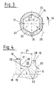
- the conical press part 5 adjoining the conveying part 4 runs in a press insert 7 of a conical mouthpiece 6, into which, in a front region 12 seen in the conveying direction 11, axially extending, trains 23 and fields 30 are incorporated, with a front seen in the conveying direction 11 Area 8 of the press part 5 with a circumferential gap 10 of 0.5 to 1 mm between the end face 28 of the screw turn 16 and the inner wall 31 of the press insert 7 of the mouthpiece 6.
- the conveying surface 17 includes with the axis 18 of the press screw 3 an angle 19 of 92 degrees in the conveying direction 11, which are just sufficient to establish and maintain a frictional connection with the trains 23 of the press insert 7 over the material to be pressed.
- transition radius 20 between the conveying surface 17 and the conical screw core 22 is kept as small as possible and is less than half the radial height 26 of the conveying surface 17, as a result of which the radial components of the pressing forces are kept low at this point.
- the trains 23 of the press insert 7 are in the front region 12 of the mouthpiece 6, as seen in the conveying direction 11 attached and have a width 24 in the direction of rotation 33 of the pressing part 5, which is less than the width of an adjacent field 30. They deepen from a flat start to a depth 25, which is less than the width 24 of a train 23 and sweep with a steep curvature 34 to the inner wall 31, which forms the field 30, forming a scraper edge 35.
- This scraper edge 35 has an edge angle 36 which is approximately 120 degrees and on the one hand reduces wear and on the other hand prevents tearing of the material to be pressed.
- An outlet area 13 adjoins the front area 12 of the mouthpiece 6 or of the press insert 7, the taper angle of which with the axis 18 of the press screw 3 is between 5 and 10 degrees, and preferably 7 degrees, which is slightly increased by approximately 0.5 to 2 Angular degrees, preferably 1 angular degree, to avoid clogging or sticking when restarting after a standstill.
- a cylindrical or slightly widened transition area 15 is provided, in which the trains 23 begin to flatten out and at which the rear area 9 of the pressing part 5 begins.
- the material to be pressed begins to separate from the press screw 3 and is pressed through the outlet area 13 and through the outlet opening 14, where jaws 37, 37 'of a pressing tongs 32 hold the material to be pressed and hold it back in a controlled manner in order to provide the necessary counterpressure for perfect compression to create.
- the material to be pressed is released in the form of irregularly broken compacts 2.
Landscapes
- Engineering & Computer Science (AREA)
- Mechanical Engineering (AREA)
- Processing Of Solid Wastes (AREA)
- Press Drives And Press Lines (AREA)
- Materials For Medical Uses (AREA)
- Extrusion Moulding Of Plastics Or The Like (AREA)
- Paper (AREA)
Claims (18)
- Extrudeuse pour la compression de matières fibreuses, en particulier vieux papier, munie d'une vis sans fin (3), montée flottante, entrainée par un moteur d'entrainement à engrenage, et se composant d'un dispositif de transport roulant dans un entonnoir ouvert (4) et d'une partie pressante (5) se retrécissant de manière conique avec au moins une hélice sans fin (16) à accès unique, dont le plan de transport (17) pour la compression du matériel à presser forme un angle (19) d'au moins 90 degrés avec l'axe (18) de la vis sans fin (3), qui, en direction du convoyeur (11), et ce vers son orifice de sortie (14), se transforme en une machoire conique étroite (6), présentant une partie avant (8), vu en direction du convoyeur (11) du matériel à compresser, au-delà de laquelle la partie frontale (28) de l'hélice sans fin (16) et vu en direction du plan de transport (11), travaillant avec la partie avant (12) de la machoire (6) avec une ouverture moindre (10) au moins sur une partie de son rétrécissement entrainant des champs électriques (30) et par rapport à leur largeur (24) une profondeur minime (25) des dispositifs de traction (23), caractérisé de par le fait que les dispositifs de traction (23) s'enfoncant en direction du convoyeur (11), d'ou suit, sur le plan avant (12) de la machoire (6) en direction du convoyeur (11) une zone de sortie (13), avec des dispositifs de traction (23), s'évasant faiblement en forme de cone et au debut duquel vu en direction du convoyeur (11), la partie arrière (9) de la partie pressante (5) de la vis sans fin (3) avec un rétrécissement conique, correspondant à un répétition du rétrécissement de la partie avant (8) de la partie pressante (5) se termine et rejète le materiel à presser dans une zone de sortie (13) de la machoire (6).
- Extrudeuse, selon la revendication précédente, caractérisée de par le fait qu'à la partie pressante (5) de la vis sans fin (3), il est prévu de la place (29) pour la matière à presser entre le noyau conique (22) et les voies de l'hélice sans fin (16), qu'à la partie pressante (5), vu en direction du plan de transport (11), est prévu par rapport à l'ampleur de la compression du matériel à presser, le plan de transport (17) de l'hélice sans fin (16) pour la compression du matériel à presser formant avec l'axe (18) de la vis sans fin (3) un angle (19) de plus de 90 degrés avec un radius de transition (20) sur la surface du noyau conique (22), correspondant à une partie de la hauteur radiale (26) du plan de transport (17).
- Extrudeuse, selon les revendications 1 ou 2, caractérisée de par le fait que l'angle (19) entre le plan de transport (17) de l'hélice sans fin (16) et l'axe (18) de la partie pressante (5) devra être plus grand suivant la compacité interne du matériel à presser par rapport à la force de coupe pendant le processus de compression.
- Extrudeuse, selon l'une des revendications précédentes, caractérisée de par le fait que le pas (27) de l'hélice sans fin (16) correspond au moins à la hauteur radiale (26) de celle du plan de transport (17).
- Extrudeuse, selon l'une des revendications précédentes, caractérisée de par le fait que le radius de transition (20) entre le plan de transport (17) de l'hélice sans fin (16) de la partie conique de la partie pressante (5) et la surface du noyau conique (22) devra être plus grand suivant la compacité interne du matériel à presser par rapport à la force de coupe pendant le processus de compression.
- Extrudeuse, selon l'une des revendications précédentes, caractérisée de par le fait que la hauteur radiale (26) du plan de transport (17) de l'hélice sans fin (16) n'est pas moindre que le radius du noyau (22) à cet endroit conique de la partie pressante (5).
- Extrudeuse, selon l'une des revendications précédentes, caractérisée de par le fait que la hauteur radiale (26) du plan de transport (17) de l'hélice sans fin (16) de la partie conique de la presse (5) disparait dans le domaine arrière (9) de la partie pressante (5) jusqu'à sa fin en forme sphérique (21).
- Extrudeuse, selon les revendications précédentes, caractérisée de par le fait que la mâchoire conique (6) de l'extrudeuse (1) pourvue d'un châssis de presse (7) avec sur le plan avant (12) les dispositifs de traction (23) et les champs électriques (30), se rétrécissant de manière conique en direction du convoyeur (11) présentant une zone de sortie (13) et s'élargissant légèrement vers un orifice de sortie (14).
- Extrudeuse, selon l'une des revendications précédentes, caractérisée de par le fait que la mâchoire conique (6) ou le châssis de la presse (7) présente entre la partie avant (12) et l'orifice de sortie (13) une zone (15) un peu cylindrique ou faiblement évasée.
- Extrudeuse, selon l'une des revendications précédentes, caractérisée de par le fait que la mâchoire (6) ou le châssis de la presse (7) sont pourvus de dispositifs de traction axiaux (23) et de champs électriques (30), les champs électriques (30) prenant au moins la même surface de la paroi interne (31) de la mâchoire (6) ou du châssis de la presse (7) de même que les dispositifs de traction (23).
- Extrudeuse, selon l'une des revendications précédentes, caractérisée de par le fait que sur le plan avant (12) de la mâchoire (6) ou du châssis de la presse (7) se trouvent plusieurs entortillements de l'hélice sans fin (16) de la partie conique de la presse (5) et cela d'une longueur axiale plus grande si la consistance du matériel à presser est moindre que la force de coupe lors de la procédure de compression.
- Extrudeuse, selon l'une des revendications précédentes, caractérisée de par le fait que les dispositifs de traction (23) de la mâchoire (6) ou du châssis de la presse (7) ont une largeur (24) correspondant à plusieurs fois celle de leur profondeur (25).
- Extrudeuse, selon l'une des revendications précédentes, caractérisée de par le fait que chaque champ électrique (23) de la mâchoire (6) ou du châssis de la presse (7) présente un tracé arrondi, s'approfondissant en un mouvement circulaire surperficiel (33) du plan de presse (5) et se terminant par une courbe abrupte (34) ou superficie, formant une arête de balayage (35) avec le champ électrique suivant (30).
- Extrudeuse, selon l'une des revendications précédentes, caractérisée de par le fait que l'arête de balayage (35) est formée d'un angle obtus (36) entre dispositif de traction (23) et champ électrique (30).
- Extrudeuse, selon l'une des revendications précédentes, caractérisée de par le fait qu'au moins cinq dispositifs de traction (23) commencent à se developper d'une facon plane au niveau du champ électrique (30).
- Extrudeuse, selon l'une des revendications précédentes, caractérisée de par le fait qu'au moins cinq dispositifs de traction (23) au mieux six, sont répartis régulièrement sur la paroi (31) de la mâchoire (6) ou du châssis de la presse (7).
- Extrudeuse, selon l'une des revendications précédentes, caractérisée de par le fait que le balayage du matériel à presser se fait dans la zone arrière (9) de la partie de la presse (5), en grande partie à l'endroit le plus étroit de la mâchoire (6) ou du châssis de la presse (7), la même chose se produisant dans la zone de transition entre la partie avant (12) et l'orifice de sortie (13).
- Extrudeuse, selon l'une des revendications précédentes, caractérisée de par le fait que le matériel à presser est saisi à la sortie de l'orifice (14) de la mâchoire (6) ou du châssis de la presse (7) par une pince (32), exerçant une force supplémentaire sur le matériel dans l'extrudeuse (1), ceci dépendant de la quantité de produit et de la force de pression de la pince (32).
Applications Claiming Priority (2)
| Application Number | Priority Date | Filing Date | Title |
|---|---|---|---|
| DE4011248A DE4011248A1 (de) | 1990-04-06 | 1990-04-06 | Schneckenpresse |
| DE4011248 | 1990-04-06 |
Publications (2)
| Publication Number | Publication Date |
|---|---|
| EP0451349A1 EP0451349A1 (fr) | 1991-10-16 |
| EP0451349B1 true EP0451349B1 (fr) | 1995-05-17 |
Family
ID=6403951
Family Applications (1)
| Application Number | Title | Priority Date | Filing Date |
|---|---|---|---|
| EP90123516A Expired - Lifetime EP0451349B1 (fr) | 1990-04-06 | 1990-12-07 | Presse à vis |
Country Status (5)
| Country | Link |
|---|---|
| EP (1) | EP0451349B1 (fr) |
| JP (1) | JP3253645B2 (fr) |
| AT (1) | ATE122605T1 (fr) |
| DE (2) | DE4011248A1 (fr) |
| HU (1) | HU210782B (fr) |
Families Citing this family (10)
| Publication number | Priority date | Publication date | Assignee | Title |
|---|---|---|---|---|
| DE4345322C2 (de) * | 1992-07-03 | 1999-08-05 | Fuji Xerox Engineering Co Ltd | Vorrichtung zum Verdichten von zu kleinen Partikeln zerkleinertem Altpapier |
| US5427321A (en) * | 1992-07-03 | 1995-06-27 | Meiden Plant Engineering & Construction Co., Ltd. | Waste paper processing system |
| GB2285407A (en) * | 1993-12-14 | 1995-07-12 | Kobe Steel Ltd | Apparatus for molding fibrous material containing waste paper |
| DE10031047C2 (de) * | 2000-06-26 | 2003-05-15 | Hamme Christina | Verfahren und Vorrichtung zur Herstellung eines rieselfähigen Schüttgutes |
| DE202014001409U1 (de) * | 2014-02-13 | 2014-02-25 | Röhren- Und Pumpenwerk Bauer Ges.M.B.H. | Pressschneckenseparator und Verschleißring |
| CN108160664B (zh) * | 2017-12-12 | 2023-05-02 | 广东利世康低碳科技有限公司 | 一种能有效回收餐厨垃圾压榨渣中有机物的处理装置 |
| CN108436200B (zh) * | 2018-05-13 | 2023-09-01 | 陕西理工大学 | 大导程螺母的双电机伺服直驱螺旋挤压装置 |
| CN109291497B (zh) * | 2018-10-12 | 2024-07-09 | 北京晟智科技发展有限公司 | 一种废弃有机物就地处理设备挤压机可变径网筒 |
| CN110369445A (zh) * | 2019-07-15 | 2019-10-25 | 上海永玺环境科技有限公司 | 一种树穴盖板的制造方法 |
| CN110776970B (zh) * | 2019-11-22 | 2024-05-31 | 北控十方(山东)环保能源集团有限公司 | 一种型炭加工系统 |
Family Cites Families (6)
| Publication number | Priority date | Publication date | Assignee | Title |
|---|---|---|---|---|
| GB229769A (en) * | 1923-12-01 | 1925-03-02 | Albert William Sizer | Improvements in extrusion machines of the worm screw type |
| CA910712A (en) * | 1970-06-29 | 1972-09-26 | British Columbia Research Council | Process and apparatus for rapidly producing fuel logs |
| BE789885A (nl) * | 1971-10-19 | 1973-04-10 | Shell Int Research | Extrudeerinrichting |
| US3956981A (en) * | 1974-01-29 | 1976-05-18 | John N. Valianos | Method for refuse disposal |
| US4074803A (en) * | 1976-04-23 | 1978-02-21 | American Defibrator, Inc. | Screw conveyor having stopper bar means |
| AT371058B (de) * | 1980-11-10 | 1983-05-25 | Maplan Masch Tech Anlagen | Doppelschneckenpresse |
-
1990
- 1990-04-06 DE DE4011248A patent/DE4011248A1/de not_active Withdrawn
- 1990-12-07 AT AT90123516T patent/ATE122605T1/de not_active IP Right Cessation
- 1990-12-07 DE DE59009099T patent/DE59009099D1/de not_active Expired - Fee Related
- 1990-12-07 EP EP90123516A patent/EP0451349B1/fr not_active Expired - Lifetime
-
1991
- 1991-04-04 HU HU911096A patent/HU210782B/hu not_active IP Right Cessation
- 1991-04-05 JP JP07331791A patent/JP3253645B2/ja not_active Expired - Fee Related
Also Published As
| Publication number | Publication date |
|---|---|
| JPH06210498A (ja) | 1994-08-02 |
| HU911096D0 (en) | 1991-10-28 |
| HUT60666A (en) | 1992-10-28 |
| JP3253645B2 (ja) | 2002-02-04 |
| ATE122605T1 (de) | 1995-06-15 |
| HU210782B (en) | 1995-07-28 |
| DE4011248A1 (de) | 1991-10-10 |
| DE59009099D1 (de) | 1995-06-22 |
| EP0451349A1 (fr) | 1991-10-16 |
Similar Documents
| Publication | Publication Date | Title |
|---|---|---|
| EP2065173B1 (fr) | Surface d'arbre de vis sans fin | |
| DE202011102083U1 (de) | Schlauchnippel und Schlauchanordnung | |
| CH629863A5 (de) | Vorrichtung zum defibrieren und aufbereiten von zellulosehaltigem material. | |
| DE69617929T2 (de) | Schraubenverdichter und auslassteil für schraubenverdichter | |
| EP0451349B1 (fr) | Presse à vis | |
| DE1502243A1 (de) | Schneckenpresse | |
| EP2638205B1 (fr) | Commande de tire-toron | |
| EP0447854B1 (fr) | Dispositif de coupe pour destructeur de documents | |
| DE2717337C2 (de) | Schneckenförderer | |
| DD157204A5 (de) | Vorrichtung zum herstellen eines garnes | |
| DE4300536A1 (de) | Garniturring für Auflösewalzen von OE-Spinnmaschinen | |
| DE2143401C2 (de) | Pumpe | |
| EP0633416B1 (fr) | Dispositif et procédé pour l'étranglement d'un écoulement d'une suspension fluide sans obstruction | |
| DE3342812A1 (de) | Vorrichtung und verfahren zur extrusion von zellulosehaltigen stoffen | |
| EP0330003B2 (fr) | Extrudeuse | |
| DE1653802B2 (de) | Pumpe zum foerdern von faserigen, dickfluessigen fluessigkeiten, wie mist, mit hohem gehalt an trockenmasse | |
| DE2434397A1 (de) | Turbine | |
| EP0324800B1 (fr) | Laminoir de melange et de cisaillement pour materiaux plastifiables | |
| DE4142653A1 (de) | Zusammengesetzte schnecke fuer einen extruder fuer die keramische industrie | |
| DE69312500T2 (de) | Verfahren und vorrichtung zur herstellung einer schnecke für schneckenförderer | |
| DE102011105075A1 (de) | Schlauchnippel und Schlauchanordnung | |
| WO2011107339A1 (fr) | Procédé de broyage de fibres de cellulose dans une suspension aqueuse et garnitures de broyage pour sa mise en œuvre | |
| DE3521964A1 (de) | Vorrichtung zum herstellen eines garnes | |
| DE19601128C2 (de) | Schneckenpresse | |
| DE29619377U1 (de) | Selbstschneidende Schraube |
Legal Events
| Date | Code | Title | Description |
|---|---|---|---|
| PUAI | Public reference made under article 153(3) epc to a published international application that has entered the european phase |
Free format text: ORIGINAL CODE: 0009012 |
|
| AK | Designated contracting states |
Kind code of ref document: A1 Designated state(s): AT BE CH DE DK ES FR GB IT LI NL SE |
|
| 17P | Request for examination filed |
Effective date: 19920407 |
|
| 17Q | First examination report despatched |
Effective date: 19930729 |
|
| GRAA | (expected) grant |
Free format text: ORIGINAL CODE: 0009210 |
|
| AK | Designated contracting states |
Kind code of ref document: B1 Designated state(s): AT BE CH DE DK ES FR GB IT LI NL SE |
|
| PG25 | Lapsed in a contracting state [announced via postgrant information from national office to epo] |
Ref country code: IT Free format text: LAPSE BECAUSE OF FAILURE TO SUBMIT A TRANSLATION OF THE DESCRIPTION OR TO PAY THE FEE WITHIN THE PRESCRIBED TIME-LIMIT;WARNING: LAPSES OF ITALIAN PATENTS WITH EFFECTIVE DATE BEFORE 2007 MAY HAVE OCCURRED AT ANY TIME BEFORE 2007. THE CORRECT EFFECTIVE DATE MAY BE DIFFERENT FROM THE ONE RECORDED. Effective date: 19950517 Ref country code: BE Effective date: 19950517 Ref country code: DK Effective date: 19950517 Ref country code: FR Effective date: 19950517 Ref country code: GB Effective date: 19950517 Ref country code: NL Free format text: LAPSE BECAUSE OF NON-PAYMENT OF DUE FEES Effective date: 19950517 Ref country code: ES Free format text: THE PATENT HAS BEEN ANNULLED BY A DECISION OF A NATIONAL AUTHORITY Effective date: 19950517 |
|
| REF | Corresponds to: |
Ref document number: 122605 Country of ref document: AT Date of ref document: 19950615 Kind code of ref document: T |
|
| REF | Corresponds to: |
Ref document number: 59009099 Country of ref document: DE Date of ref document: 19950622 |
|
| PG25 | Lapsed in a contracting state [announced via postgrant information from national office to epo] |
Ref country code: SE Effective date: 19950817 |
|
| EN | Fr: translation not filed | ||
| NLV1 | Nl: lapsed or annulled due to failure to fulfill the requirements of art. 29p and 29m of the patents act | ||
| GBV | Gb: ep patent (uk) treated as always having been void in accordance with gb section 77(7)/1977 [no translation filed] |
Effective date: 19950517 |
|
| PLBE | No opposition filed within time limit |
Free format text: ORIGINAL CODE: 0009261 |
|
| 26N | No opposition filed | ||
| PGFP | Annual fee paid to national office [announced via postgrant information from national office to epo] |
Ref country code: AT Payment date: 20021125 Year of fee payment: 13 |
|
| PGFP | Annual fee paid to national office [announced via postgrant information from national office to epo] |
Ref country code: CH Payment date: 20030305 Year of fee payment: 13 |
|
| PGFP | Annual fee paid to national office [announced via postgrant information from national office to epo] |
Ref country code: DE Payment date: 20031119 Year of fee payment: 14 |
|
| PG25 | Lapsed in a contracting state [announced via postgrant information from national office to epo] |
Ref country code: AT Free format text: LAPSE BECAUSE OF NON-PAYMENT OF DUE FEES Effective date: 20031207 |
|
| PG25 | Lapsed in a contracting state [announced via postgrant information from national office to epo] |
Ref country code: LI Free format text: LAPSE BECAUSE OF NON-PAYMENT OF DUE FEES Effective date: 20031231 Ref country code: CH Free format text: LAPSE BECAUSE OF NON-PAYMENT OF DUE FEES Effective date: 20031231 |
|
| REG | Reference to a national code |
Ref country code: CH Ref legal event code: PL |
|
| PG25 | Lapsed in a contracting state [announced via postgrant information from national office to epo] |
Ref country code: DE Free format text: LAPSE BECAUSE OF NON-PAYMENT OF DUE FEES Effective date: 20050701 |