EP0451358B1 - Secoueur de paille pour moissonneuse-batteuse - Google Patents
Secoueur de paille pour moissonneuse-batteuse Download PDFInfo
- Publication number
- EP0451358B1 EP0451358B1 EP90124675A EP90124675A EP0451358B1 EP 0451358 B1 EP0451358 B1 EP 0451358B1 EP 90124675 A EP90124675 A EP 90124675A EP 90124675 A EP90124675 A EP 90124675A EP 0451358 B1 EP0451358 B1 EP 0451358B1
- Authority
- EP
- European Patent Office
- Prior art keywords
- straw walker
- assembly according
- coupling rod
- support
- coupling
- Prior art date
- Legal status (The legal status is an assumption and is not a legal conclusion. Google has not performed a legal analysis and makes no representation as to the accuracy of the status listed.)
- Expired - Lifetime
Links
- 239000010902 straw Substances 0.000 title claims description 17
- 230000008878 coupling Effects 0.000 claims description 23
- 238000010168 coupling process Methods 0.000 claims description 23
- 238000005859 coupling reaction Methods 0.000 claims description 23
- 241001124569 Lycaenidae Species 0.000 claims description 6
- 239000000463 material Substances 0.000 claims 2
- 230000000694 effects Effects 0.000 description 1
- 238000003306 harvesting Methods 0.000 description 1
- 230000001737 promoting effect Effects 0.000 description 1
- 238000000926 separation method Methods 0.000 description 1
Images
Classifications
-
- B—PERFORMING OPERATIONS; TRANSPORTING
- B07—SEPARATING SOLIDS FROM SOLIDS; SORTING
- B07B—SEPARATING SOLIDS FROM SOLIDS BY SIEVING, SCREENING, SIFTING OR BY USING GAS CURRENTS; SEPARATING BY OTHER DRY METHODS APPLICABLE TO BULK MATERIAL, e.g. LOOSE ARTICLES FIT TO BE HANDLED LIKE BULK MATERIAL
- B07B1/00—Sieving, screening, sifting, or sorting solid materials using networks, gratings, grids, or the like
- B07B1/28—Moving screens not otherwise provided for, e.g. swinging, reciprocating, rocking, tilting or wobbling screens
- B07B1/286—Moving screens not otherwise provided for, e.g. swinging, reciprocating, rocking, tilting or wobbling screens with excentric shafts
-
- A—HUMAN NECESSITIES
- A01—AGRICULTURE; FORESTRY; ANIMAL HUSBANDRY; HUNTING; TRAPPING; FISHING
- A01F—PROCESSING OF HARVESTED PRODUCE; HAY OR STRAW PRESSES; DEVICES FOR STORING AGRICULTURAL OR HORTICULTURAL PRODUCE
- A01F12/00—Parts or details of threshing apparatus
- A01F12/30—Straw separators, i.e. straw walkers, for separating residual grain from the straw
- A01F12/38—Straw separators, i.e. straw walkers, for separating residual grain from the straw with juxtaposed and independently-moved shaker bars or the like
Definitions
- the invention relates to a tray shaker for self-propelled combine harvesters, the individual tray shakers of which are movably mounted on a support both in the area of the crop entry and in the area of the crop discharge, which are connected via rocker arms and coupling rods to an eccentric drive arranged approximately centrally under a tray shaker that each of the two coupling rods are connected at one end to the eccentric drive and at the other ends with a rocker arm.
- Combine harvesters are known to be moved by two crankshafts. These shaker drives have the disadvantage that the shaker only executes a circular parallel movement. The circular movement gives only a relatively weak one Filling up so that grain losses are still relatively large.
- the start-side end of the shaker performs an elliptical movement.
- the crank rod is provided with a vibration bearing located on the side of the connection to the shaker, which forms the support bearing for the part of the shaker at the start.
- this part of the shaker describes an elliptical movement during its back and forth movement generated by the crank mechanism, such that the major axis of the ellipse extends essentially in the longitudinal direction of the shaker.
- the discharge end of the shaker is carried by a swing arm.
- a disadvantage of this embodiment is that only one end of the shaker is moved elliptically, while the other end only carries out a reciprocating movement. Thus, a shaking effect only occurs at the ellipse, while at the other end only a promotional effect occurs.
- Another disadvantage is that the major axis of the ellipse is approximately horizontal. As a result, the straw is passed over the shaker relatively quickly, ie the time in which the straw remains on the shaker is very short and the shaking out is therefore low.
- the drive crankshaft has two drive cranks which are arranged offset from one another, one of which has a coupling rod with the shaker, the other has at least one coupling rod and a rocker arm with one on
- the shaker is articulated to the pendulum support in the drive connection.
- Such an arrangement enables the shaker to move elliptically, in parallel over its entire length.
- the main axis of the ellipse is vertical or approximately vertical, so that the lifting movement of the shaker is very large and shakes the long straw transported on it.
- Practice has now shown that none of the latter arrangements can meet the requirements placed on modern combine harvesters. These requirements consist of being able to use combine harvesters in a wide variety of weather conditions to harvest a wide variety of crops, with the best possible result being achieved with regard to residual grain separation in all cases.
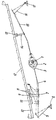
- 1 is a drive shaft on which an eccentric disc 2 is firmly attached.
- the eccentric disc 2 is surrounded by a housing 3 which encompasses the eccentric disc 2 in a freely rotatable manner.
- a coupling rod 4 is firmly connected, which is articulated with its end facing away from the housing 3 to the upper end of a rocker 5.
- the lower end of the rocker 5 is pivotally mounted in a machine-mounted base 6.
- a carriage 7 On the Coupling rod 4 is a carriage 7 which can be locked in any position with the coupling rod 4 and on which a support 8 is fastened.
- the upper end of the support 8 has a fastening head 9 which is connected to a rail 10.
- This rail 10 has a plurality of locking holes, so that the head 9 can be locked in any position of the carriage 7 on the coupling rod 4 in one of the holes 11.
- the rail itself is firmly connected to the end of a shaker tray 12 on the inlet side.
- a bracket 13 is welded to it, with which a support 14 is connected in an articulated manner.
- the end of the support 14 facing away from the bracket 13 is firmly seated on a coupling rod 15, which is connected at one end to the housing 3 in an articulated manner and at the other end to the upper end of a rocker arm 16.
- the end of the rocker which faces away from the coupling rod 15, like the rocker 5, is pivotably mounted on a machine-mounted bearing bracket 17.
Landscapes
- Life Sciences & Earth Sciences (AREA)
- Environmental Sciences (AREA)
- Combined Means For Separation Of Solids (AREA)
- Threshing Machine Elements (AREA)
Claims (8)
- Secoueur à claies pour moissonneuse-batteuse automotrice, dont les claies de secouage individuelles sont montées de façon mobile sur des appuis respectifs dans la région d'entrée des produits ainsi que dans la région de sortie des produits, appuis qui sont en liaison par l'intermédiaire de leviers oscillants et de tiges d'accouplement avec un dispositif d'entraînement excentrique disposé sensiblement centralement au-dessous d'une claie de secouage, les deux tiges d'accouplement étant reliées à une extrémité avec le dispositif d'entraînement excentrique et à l'autre extrémité avec un levier oscillant, caractérisé en ce que chaque appui (8, 14) est relié à une tige d'accouplement (4, 15) et en ce qu'au moins l'un des deux appuis (8, 14) est relié de façon déplaçable aussi bien avec la claie de secouage (12) qu'avec la tige d'actionnement (4) qui lui sont associées.
- Secoueur à claies selon la revendication 1, caractérisé en ce que les leviers oscillants (5, 16) sont montés par leurs extrémités qui sont à l'opposé des tiges d'accouplement (4, 15) sur des consoles (7) solidaires du châssis de la moissonneuse-batteuse.
- Secoueur à claies selon les revendications 1 et 2, caractérisé en ce que l'appui (8) est monté sur la tige d'accouplement (4) au moyen d'un coulisseau (7) qui peut être verrouillé dans des positions diverses sur la tige d'accouplement (4).
- Secoueur à claies selon les revendications 1 à 3, caractérisé en ce que l'appui (8) peut être verrouillé dans des positions diverses au moyen d'un rail (10) monté sur la claie de secouage (12).
- Secoueur à claies selon les revendications 1 à 4, caractérisé en ce que les tiges d'accouplement (4, 15) sont reliées au logement (3), ce dernier entourant le disque excentrique (12) de manière que ce dernier puisse tourner librement, le disque excentrique (2) étant solidaire d'un arbre d'entraînement (1).
- Secoueur à claies selon les revendications 1 à 5, caractérisé en ce qu'une tige d'accouplement (4) est reliée fermement au logement qui entoure le disque excentrique (2).
- Secoueur à claies selon les revendications 1 à 6, caractérisé en ce qu'une tige d'accouplement (15) est reliée de façon articulée avec le logement (3) qui entoure le disque excentrique (2).
- Secoueur à claies selon les revendications 1 à 7, caractérisé en ce que l'appui (14) est relié de façon articulée par une extrémité à la claie de secouage et de façon rigide par son autre extrémité à la tige d'accouplement (15) qui lui sont associées.
Applications Claiming Priority (2)
| Application Number | Priority Date | Filing Date | Title |
|---|---|---|---|
| DE4006513 | 1990-03-02 | ||
| DE4006513A DE4006513A1 (de) | 1990-03-02 | 1990-03-02 | Hordenschuettler fuer selbstfahrende maehdrescher |
Publications (2)
| Publication Number | Publication Date |
|---|---|
| EP0451358A1 EP0451358A1 (fr) | 1991-10-16 |
| EP0451358B1 true EP0451358B1 (fr) | 1994-01-12 |
Family
ID=6401253
Family Applications (1)
| Application Number | Title | Priority Date | Filing Date |
|---|---|---|---|
| EP90124675A Expired - Lifetime EP0451358B1 (fr) | 1990-03-02 | 1990-12-19 | Secoueur de paille pour moissonneuse-batteuse |
Country Status (2)
| Country | Link |
|---|---|
| EP (1) | EP0451358B1 (fr) |
| DE (2) | DE4006513A1 (fr) |
Families Citing this family (6)
| Publication number | Priority date | Publication date | Assignee | Title |
|---|---|---|---|---|
| DE10314081B4 (de) * | 2003-03-28 | 2010-07-08 | Deere & Company, Moline | Austrageinrichtung zum Austragen von Erntegut aus einer Erntemaschine |
| EP1584225B2 (fr) | 2004-04-06 | 2010-12-08 | CLAAS Selbstfahrende Erntemaschinen GmbH | Moisonneuse-batteuse |
| RU2373682C2 (ru) * | 2004-04-15 | 2009-11-27 | КЛААС Зельбстфаренде Эрнтемашинен ГмбХ | Способ и устройство для эксплуатации зерноуборочного комбайна |
| DE102006006938A1 (de) * | 2006-02-14 | 2007-08-30 | Claas Selbstfahrende Erntemaschinen Gmbh | Mähdrescher mit Hordenschüttler |
| NL2004293C2 (nl) * | 2010-02-24 | 2011-08-25 | Potveer Bv | Schoksorteerinrichting. |
| BE1023017B1 (nl) | 2015-06-30 | 2016-11-04 | Cnh Industrial Belgium Nv | Maaidorser met stroschudders met verstelbare helling |
Family Cites Families (13)
| Publication number | Priority date | Publication date | Assignee | Title |
|---|---|---|---|---|
| DE44604C (de) * | H. diekmann in Dortmund | Tafelsieb | ||
| DE52300C (fr) * | ||||
| GB177359A (en) * | 1921-02-22 | 1922-03-30 | Hugo Schubert | Straw shaker for thrashing machines |
| FR1112270A (fr) * | 1954-10-06 | 1956-03-12 | Westerasmaskiner Ab | Dispositif monté sur le secoueur d'un appareil de battage |
| DE1167090B (de) * | 1960-06-21 | 1964-04-02 | Fahr Ag Maschf | Selbstfahrender Maehdrescher als Mehrzweckmaschine |
| DE1148099B (de) * | 1962-05-03 | 1963-05-02 | John Deere Lanz Ag | Schuettlerantrieb fuer Dreschmaschinen und Maehdrescher |
| FR1335156A (fr) * | 1962-07-07 | 1963-08-16 | Fahr Ag Maschf | Moissonneuse-batteuse avec trémie à grains |
| DE1482021A1 (de) * | 1964-12-10 | 1969-06-04 | Hege Dipl Landw Hans Ulrich | Fahrbare Maehdreschmaschine |
| US3513855A (en) * | 1967-08-30 | 1970-05-26 | Int Harvester Co | Straw rack drive |
| US3627277A (en) * | 1970-04-17 | 1971-12-14 | Joseph A Amori | Shaker bed system |
| GB1602099A (en) * | 1978-05-12 | 1981-11-04 | Tickhill Eng Co Ltd | Grading apparatus |
| DE3114382C2 (de) * | 1981-04-09 | 1986-11-20 | Claas Ohg, 4834 Harsewinkel | Schüttlerloser selbstfahrender Mähdrescher |
| DE3530566A1 (de) * | 1985-08-27 | 1987-03-12 | Kloeckner Humboldt Deutz Ag | Maehdrescher |
-
1990
- 1990-03-02 DE DE4006513A patent/DE4006513A1/de not_active Withdrawn
- 1990-12-19 DE DE90124675T patent/DE59004241D1/de not_active Expired - Fee Related
- 1990-12-19 EP EP90124675A patent/EP0451358B1/fr not_active Expired - Lifetime
Also Published As
| Publication number | Publication date |
|---|---|
| DE4006513A1 (de) | 1991-09-05 |
| EP0451358A1 (fr) | 1991-10-16 |
| DE59004241D1 (de) | 1994-02-24 |
Similar Documents
| Publication | Publication Date | Title |
|---|---|---|
| DE3008385C2 (de) | Vorrichtung zum Verteilen von Siebgut | |
| DE602005004446T2 (de) | Getreidereinigung im Mähdrescher | |
| DE3235087C2 (de) | Hackfruchterntemaschine | |
| DE1582642A1 (de) | Maehdrescher | |
| DE60000434T2 (de) | Erntemaschine für früchte und beeren und rüttelstab für solche maschinen | |
| DE8800121U1 (de) | Sieb- und Fördereinrichtung | |
| DE3530566C2 (fr) | ||
| EP0451358A1 (fr) | Secoueur de paille pour moissonneuse-batteuse | |
| DE2245125A1 (de) | Maehdrescher | |
| DE8100584U1 (de) | Hordenschüttler für Mähdrescher | |
| DE2632560A1 (de) | Reinigungsvorrichtung an maehdreschern | |
| CH658364A5 (de) | Futtererntemaschine mit seitlicher foerderung. | |
| DE1155627B (de) | Hordenschuettler fuer Dreschmaschinen, insbesondere fuer Maehdrescher | |
| DE3441238C2 (fr) | ||
| DE2923022C2 (fr) | ||
| DE4036931A1 (de) | Hordenschuettler fuer selbstfahrende maehdrescher | |
| DE1148099B (de) | Schuettlerantrieb fuer Dreschmaschinen und Maehdrescher | |
| DE1800498A1 (de) | Fahrbare Presse | |
| DE3504003C2 (fr) | ||
| DE3620747C2 (fr) | ||
| DE2504354B2 (de) | Vorrichtung zum Verteilen und Lockern des aus der Dreschvorrichtung eines Mähdreschers anfallenden Gutes | |
| DE1936095A1 (de) | Siebeinrichtung fuer Maehdrescher | |
| DE1782427C (de) | Strohschüttler für Dreschmaschinen, insbesondere Mähdrescher | |
| DE2743733A1 (de) | Selbstfahrende erntemaschine, insbesondere maehdrescher | |
| DE924596C (de) | Plansieb-Kartoffelsortiermaschine |
Legal Events
| Date | Code | Title | Description |
|---|---|---|---|
| PUAI | Public reference made under article 153(3) epc to a published international application that has entered the european phase |
Free format text: ORIGINAL CODE: 0009012 |
|
| AK | Designated contracting states |
Kind code of ref document: A1 Designated state(s): BE DE FR GB IT |
|
| 17P | Request for examination filed |
Effective date: 19911030 |
|
| 17Q | First examination report despatched |
Effective date: 19930614 |
|
| RBV | Designated contracting states (corrected) |
Designated state(s): BE DE FR |
|
| GRAA | (expected) grant |
Free format text: ORIGINAL CODE: 0009210 |
|
| AK | Designated contracting states |
Kind code of ref document: B1 Designated state(s): BE DE FR |
|
| REF | Corresponds to: |
Ref document number: 59004241 Country of ref document: DE Date of ref document: 19940224 |
|
| ET | Fr: translation filed | ||
| PLBE | No opposition filed within time limit |
Free format text: ORIGINAL CODE: 0009261 |
|
| STAA | Information on the status of an ep patent application or granted ep patent |
Free format text: STATUS: NO OPPOSITION FILED WITHIN TIME LIMIT |
|
| 26N | No opposition filed | ||
| PGFP | Annual fee paid to national office [announced via postgrant information from national office to epo] |
Ref country code: DE Payment date: 20031111 Year of fee payment: 14 |
|
| PGFP | Annual fee paid to national office [announced via postgrant information from national office to epo] |
Ref country code: FR Payment date: 20041221 Year of fee payment: 15 |
|
| PGFP | Annual fee paid to national office [announced via postgrant information from national office to epo] |
Ref country code: BE Payment date: 20050112 Year of fee payment: 15 |
|
| PG25 | Lapsed in a contracting state [announced via postgrant information from national office to epo] |
Ref country code: DE Free format text: LAPSE BECAUSE OF NON-PAYMENT OF DUE FEES Effective date: 20050701 |
|
| PG25 | Lapsed in a contracting state [announced via postgrant information from national office to epo] |
Ref country code: BE Free format text: LAPSE BECAUSE OF NON-PAYMENT OF DUE FEES Effective date: 20051231 |
|
| PG25 | Lapsed in a contracting state [announced via postgrant information from national office to epo] |
Ref country code: FR Free format text: LAPSE BECAUSE OF NON-PAYMENT OF DUE FEES Effective date: 20060831 |
|
| REG | Reference to a national code |
Ref country code: FR Ref legal event code: ST Effective date: 20060831 |
|
| BERE | Be: lapsed |
Owner name: *CLAAS OHG Effective date: 20051231 |