EP0451616B1 - Gerüstboden - Google Patents
Gerüstboden Download PDFInfo
- Publication number
- EP0451616B1 EP0451616B1 EP91104835A EP91104835A EP0451616B1 EP 0451616 B1 EP0451616 B1 EP 0451616B1 EP 91104835 A EP91104835 A EP 91104835A EP 91104835 A EP91104835 A EP 91104835A EP 0451616 B1 EP0451616 B1 EP 0451616B1
- Authority
- EP
- European Patent Office
- Prior art keywords
- wall
- support
- scaffold floor
- centring
- section
- Prior art date
- Legal status (The legal status is an assumption and is not a legal conclusion. Google has not performed a legal analysis and makes no representation as to the accuracy of the status listed.)
- Expired - Lifetime
Links
- 238000003780 insertion Methods 0.000 claims abstract description 11
- 230000037431 insertion Effects 0.000 claims abstract description 11
- 238000006073 displacement reaction Methods 0.000 claims abstract description 8
- 230000002787 reinforcement Effects 0.000 claims description 8
- 239000000463 material Substances 0.000 claims description 6
- 238000009825 accumulation Methods 0.000 claims description 5
- 239000002184 metal Substances 0.000 claims description 4
- 230000003014 reinforcing effect Effects 0.000 claims description 2
- 230000015572 biosynthetic process Effects 0.000 description 6
- 238000004519 manufacturing process Methods 0.000 description 4
- 230000035508 accumulation Effects 0.000 description 3
- 230000002349 favourable effect Effects 0.000 description 2
- 229910000831 Steel Inorganic materials 0.000 description 1
- 238000005452 bending Methods 0.000 description 1
- 238000010276 construction Methods 0.000 description 1
- 238000001125 extrusion Methods 0.000 description 1
- 239000011120 plywood Substances 0.000 description 1
- 239000010959 steel Substances 0.000 description 1
Images

Classifications
-
- E—FIXED CONSTRUCTIONS
- E04—BUILDING
- E04G—SCAFFOLDING; FORMS; SHUTTERING; BUILDING IMPLEMENTS OR AIDS, OR THEIR USE; HANDLING BUILDING MATERIALS ON THE SITE; REPAIRING, BREAKING-UP OR OTHER WORK ON EXISTING BUILDINGS
- E04G1/00—Scaffolds primarily resting on the ground
- E04G1/15—Scaffolds primarily resting on the ground essentially comprising special means for supporting or forming platforms; Platforms
- E04G1/152—Platforms made of metal or with metal-supporting frame
-
- E—FIXED CONSTRUCTIONS
- E04—BUILDING
- E04G—SCAFFOLDING; FORMS; SHUTTERING; BUILDING IMPLEMENTS OR AIDS, OR THEIR USE; HANDLING BUILDING MATERIALS ON THE SITE; REPAIRING, BREAKING-UP OR OTHER WORK ON EXISTING BUILDINGS
- E04G1/00—Scaffolds primarily resting on the ground
- E04G1/15—Scaffolds primarily resting on the ground essentially comprising special means for supporting or forming platforms; Platforms
- E04G2001/156—Stackable platforms
Definitions
- the invention relates to a scaffolding floor with a frame-like support structure composed of profile parts, which contains longitudinal spars, which are formed from sections of light metal extruded profile parts and wherein the profile has a vertical inner wall, a vertical outer wall, a horizontal lower wall, a horizontal upper wall and has further support, support and reinforcement means, under which a lower rounded support rib and inner reinforcement ribs are provided, and wherein a plate forming the running surface of the scaffold floor is fastened to the support formation.
- the invention has for its object to provide an improved spar profile for inexpensive manufacture, assembly and use.
- the profile of the longitudinal spars has only a lower, in the area of the outer corner, serving for reinforcement, support and centering, approximately semi-cylindrical centering rib and that in the area of the upper, outer corner for support reinforcement an at least the 3- times the remaining wall thickness amount of material accumulation is formed, which extends to a lower-lying contact fold limited by a folded wall, in which one Support surface for the plate is formed, and wherein the vertical fold wall extends to the upper edge of the profile, under which a displacement limiting rib and an adjoining, outward and upward stacking centering fold are designed to limit a centering space so that when stacking the Centering rib of the overhead longitudinal spar in the centering room inserts the scaffolding floors to prevent lateral displacement.
- a free space is now created on the top inwards, in which the attachment of the plate can be accommodated without problems, for example with rivets.
- the scaffolding floors are centered on each other only with the two outer position centering ribs of the two spaced-apart longitudinal spars of a scaffolding floor and in each case a centering space above a thick-walled upper area, which is delimited by a small, upwardly displaced, displacement-limiting rib and serves for stacking. Otherwise, you can stack on rivet heads.
- a profile designed in this way fulfills optimizing manufacturing, assembly and usage conditions.
- the expedient position of the inner stop and guide ribs makes it possible to receive and hold support hooks with their insertion pins in a well-guided manner at the end without incurring additional costs on the profile. So easy Riveting the plug-in pins is sufficient for further securing the position and fastening. Securing ribs on the support surface can serve to better hold the entire scaffold floor together.
- Fig. 1 only a small part of a scaffold is shown.
- the stems 20 carry perforated disks 21, which are known per se, according to the spacing of the scaffolding system. Between the stems 20, a support bolt 22 is fastened to the perforated disks 21 with the aid of connecting heads 30.
- the support bar 22 is designed as an upwardly open U-profile.
- the upper ends of the vertical legs 27.1 and 27.2 of the support bar 22 are designed as support edges 23 for the support hooks 25.1, 25.2 and 35 of the scaffold floor 26.
- the connection heads 30 are designed in a known manner with slots and plugged onto the perforated disks 21 and secured to them with wedges 34. In this or a similar way, many scaffolding days are realized in one scaffold.
- This section is only shown to illustrate how the longitudinal beam profiles according to the invention are arranged with their designs in the entire framework.
- the scaffolding floor 26 chosen here as an example has three support hooks on each end face, of which the two outer support hooks 25.1, 25.2 are fastened in the two corners and a differently designed support hook 35 in the middle.
- the support hook 35 is fastened to a cross member 36 of the support formation 37 of the scaffold floor 26, preferably welded on.
- the cross bar 36 is between the two longitudinal bars 38.1 and 38.2 of the support formation 37 of the Scaffold floor 26 welded in the area of the corners so that the cut ends 39.1 and 39.2 of the longitudinal bars 38.1 and 38.2 remain open. This results in a stable frame, possibly provided with cross bracing, not shown, which forms the support formation 37 of the scaffold floor 26. It has - as FIG.
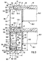
- FIG. 3 shows - contact surfaces 41 which extend over approximately 2/3 of the width 145 of the profiles 100 of the longitudinal spars 38.1, 38.2, 38.3, 38.4 and each extend up to a vertical folding wall 42.
- the edge 43 of a plate 45 is placed.
- the plate 45 can be formed from heat-resistant glued plywood with an anti-slip layer or another material that is common in scaffolding. It has the running surface 46 of the scaffold floor 26 as the surface. With the aid of rivets 47 arranged at suitable intervals, for example hollow rivets or blind rivets, the edge 43 is riveted to the longitudinal bars 38.
- FIG. 3 shows the longitudinal spars 38.3 and 38.4 of a lower scaffold floor 26.1 and an upper scaffold floor 26.2, which correspond in their position to the longitudinal spar 38.2 lying on the left in FIGS. 1 and 2.
- a transverse spar 36.1 or 36.2 is shown, which is just cut off at its ends and welded directly to it by means of weld seams 101 on the inner outer surface 113 of the inner wall 107 of the respective longitudinal spar 38 ... .
- each longitudinal spar 38 ... is a light metal extrusion profile which is cut off at the ends 39.1, 39.2.
- the profile 100 has a lower wall 105, an upper wall 106, an inner wall 107 and an outer wall 108.
- a semi-cylindrical centering rib 110 is formed below the lower wall 105. It serves to reinforce and support the scaffold floor when it is placed on a support base and in particular to center the position when stacking, as shown in FIG. 3.
- the bottom wall 105 is guided on its outer surface 111 smoothly and horizontally. It merges with a rounded corner 112 into the smooth outer surface 113 of the vertical inner wall 107.
- the outer wall 108 adjoins the lower wall 105, which has an outer wall lower part 114, an outer wall middle part 115 and an outer wall upper part 116.
- the outer wall lower part 114 and the outer wall upper part 116 are arranged in alignment with one another, while the outer wall middle part 115 is offset inwards by a small amount of, for example, 1 mm.
- the thickness 52 of this insertion pin 50 can be determined very precisely by cutting. The cutting leads to sharp-edged corners.
- the insertion pin 50 is fixed against the inner fitting surface 117 of the outer wall 108 or by a lower pin guide rib 125.1 projecting inward from the lower wall 105 in the spar space 120 and a pin guide rib 125.2 projecting downward from the upper wall 106 in the direction of the interior of the scaffolding floor of the outer wall middle part 115 held tight. Otherwise, the insertion pin 50 has an upper fitting surface 62.2 on the upper wall 56.2 and a lower fitting surface 62.1 below the lower wall 56.1, which fits on the wall surfaces 122.1 and 122.2 and the insertion pin 50 keeps the forces acting on it.
- Rivets 57 are guided through corresponding through openings 55.1 and 55.2 in fastening eyes 58.1 and 58.2 of the insertion pin 50 and the correspondingly assigned openings in the outer wall lower part 114 and in the outer wall upper part 116 and thus secure the position of the insertion pin 50 of the support hook 25, so that in all Forces acting in directions can be transmitted between support hooks 25 and longitudinal bars 38.
- the Pin guide ribs 125.1 and 125.2 are located approximately in the middle of the bottom wall 105 and top wall 106, so that there is a space in the top wall 106 offset by the rivet 47 for gripping the plate 45, as illustrated in FIG. 3 .
- the support surface 41 which is delimited by the fold wall 42, serves to support the plate 45, the support surface 41 taking up approximately 2/3 of the width of the top wall 106 of the profile 100 and the fold wall 42 with its top edge 124 slightly, for example by approximately 1 mm below the tread 46 of the plate 45 or the entire scaffold floor 26.
- a displacement limitation rib 136 is formed, which delimits an outwardly open stack centering fold 130, which is formed in that the upper wall region 131 is laid down by approximately 2 mm relative to the height of the upper edge 124 . This results - as can be seen in the middle of FIG.
- the outer width 145 has an amount of approximately 45 mm, while the outer height 146 from the lower surface 111 to the support surface 41 is approximately 62 mm.
- the support surface 41 is expediently provided with a suitable profiling, for example with longitudinally extending, pointed ribs, in order to hold the plate together with a few rivets and to reinforce the entire scaffolding floor, also against rotation.
- the cheaply designed and optimized in terms of manufacture, assembly and use profile 100 can be easily produced in the form shown in FIG. 3 without special technological effort and also with others for Part of higher dimensions can be designed cheaply to bridge longer lengths. It allows the quick assembly of stable scaffolding floors with support hooks.
- the profile (100) of the longitudinal spars (38 ...) of scaffolding floors (26) has a semi-cylindrical centering rib (110) in the lower outer corner (109), which in a centering space (135) at the top of each intervene below the longitudinal bar (38.3) and thus secure against lateral displacement.
- Inner pin guide ribs (125.1, 125.2) serve to hold an insert pin (50) of a support hook.
Landscapes
- Architecture (AREA)
- Engineering & Computer Science (AREA)
- Mechanical Engineering (AREA)
- Civil Engineering (AREA)
- Structural Engineering (AREA)
- Movable Scaffolding (AREA)
- Ladders (AREA)
- Vehicle Step Arrangements And Article Storage (AREA)
- Forms Removed On Construction Sites Or Auxiliary Members Thereof (AREA)
- Revetment (AREA)
- Mutual Connection Of Rods And Tubes (AREA)
- Joining Of Building Structures In Genera (AREA)
- Bridges Or Land Bridges (AREA)
- Electric Cable Installation (AREA)
- Surgical Instruments (AREA)
- Saccharide Compounds (AREA)
- Emergency Lowering Means (AREA)
Applications Claiming Priority (2)
| Application Number | Priority Date | Filing Date | Title |
|---|---|---|---|
| DE4011624 | 1990-04-11 | ||
| DE4011624A DE4011624A1 (de) | 1990-04-11 | 1990-04-11 | Geruestboden |
Publications (2)
| Publication Number | Publication Date |
|---|---|
| EP0451616A1 EP0451616A1 (de) | 1991-10-16 |
| EP0451616B1 true EP0451616B1 (de) | 1994-01-26 |
Family
ID=6404157
Family Applications (1)
| Application Number | Title | Priority Date | Filing Date |
|---|---|---|---|
| EP91104835A Expired - Lifetime EP0451616B1 (de) | 1990-04-11 | 1991-03-27 | Gerüstboden |
Country Status (8)
| Country | Link |
|---|---|
| EP (1) | EP0451616B1 (pt) |
| AT (1) | ATE100889T1 (pt) |
| DE (2) | DE4011624A1 (pt) |
| DK (1) | DK0451616T3 (pt) |
| ES (1) | ES2051040T3 (pt) |
| FI (1) | FI911708L (pt) |
| NO (1) | NO178204C (pt) |
| PT (1) | PT8704U (pt) |
Families Citing this family (7)
| Publication number | Priority date | Publication date | Assignee | Title |
|---|---|---|---|---|
| DE4135586C2 (de) * | 1991-10-29 | 2000-02-24 | Huennebeck Roero Gmbh | Belag für Baugerüste o. dgl. |
| DE4411452B4 (de) * | 1994-04-01 | 2004-05-06 | Wilhelm Layher Vermögensverwaltungs-Gmbh | Gerüstboden |
| DE9410468U1 (de) * | 1994-07-01 | 1995-01-19 | Krause-Werk GmbH & Co KG, 36304 Alsfeld | Belagbühne |
| DE9418062U1 (de) * | 1994-11-11 | 1995-01-19 | Krause-Werk GmbH & Co KG, 36304 Alsfeld | Arbeitsbühne |
| DE19837465A1 (de) * | 1998-08-19 | 2000-02-24 | Plettac Ag | Längsträgerprofil eines Gerüstbodens |
| DE202008013674U1 (de) | 2008-10-15 | 2010-02-25 | Wilhelm Layher Verwaltungs-Gmbh | Gerüstboden mit separatem Plattenrand-Einfassungsprofil |
| CN112459461B (zh) * | 2020-12-16 | 2021-12-14 | 安徽一诺青春工业设计有限公司灵璧分公司 | 一种便于组装的建筑浇筑顶板 |
Family Cites Families (2)
| Publication number | Priority date | Publication date | Assignee | Title |
|---|---|---|---|---|
| DE3539507A1 (de) * | 1984-11-09 | 1986-05-22 | geb. Layher Ruth 7129 Güglingen Langer | Geruestrahmentafel |
| DE3724269A1 (de) * | 1987-07-22 | 1989-02-02 | Langer Geb Layher | Geruestrahmentafel aus leichtmetall-strang-press-profilteilen |
-
1990
- 1990-04-11 DE DE4011624A patent/DE4011624A1/de not_active Withdrawn
-
1991
- 1991-03-27 EP EP91104835A patent/EP0451616B1/de not_active Expired - Lifetime
- 1991-03-27 ES ES91104835T patent/ES2051040T3/es not_active Expired - Lifetime
- 1991-03-27 AT AT91104835T patent/ATE100889T1/de not_active IP Right Cessation
- 1991-03-27 DE DE91104835T patent/DE59100926D1/de not_active Expired - Fee Related
- 1991-03-27 DK DK91104835.3T patent/DK0451616T3/da active
- 1991-04-10 FI FI911708A patent/FI911708L/fi not_active Application Discontinuation
- 1991-04-10 NO NO911391A patent/NO178204C/no not_active IP Right Cessation
-
1993
- 1993-02-18 PT PT8704U patent/PT8704U/pt not_active IP Right Cessation
Also Published As
| Publication number | Publication date |
|---|---|
| FI911708A0 (fi) | 1991-04-10 |
| NO911391D0 (no) | 1991-04-10 |
| FI911708A7 (fi) | 1991-10-12 |
| DE59100926D1 (de) | 1994-03-10 |
| DE4011624A1 (de) | 1991-10-17 |
| NO911391L (no) | 1991-10-14 |
| PT8704U (pt) | 1996-01-31 |
| NO178204B (no) | 1995-10-30 |
| ES2051040T3 (es) | 1994-06-01 |
| PT8704T (pt) | 1993-08-31 |
| ATE100889T1 (de) | 1994-02-15 |
| DK0451616T3 (da) | 1994-06-06 |
| FI911708L (fi) | 1991-10-12 |
| EP0451616A1 (de) | 1991-10-16 |
| NO178204C (no) | 1996-02-07 |
Similar Documents
| Publication | Publication Date | Title |
|---|---|---|
| EP0864489B1 (de) | Bodenelement | |
| DE202015005791U1 (de) | Transport- und/oder Lagergestell | |
| EP0736647A1 (de) | Gerüstboden | |
| EP0300399A2 (de) | Gerüstrahmentafel aus Leichtmetall-Strang-Press-Profilteilen | |
| WO2017140549A1 (de) | Laufrollenträger und transportvorrichtung | |
| EP0451616B1 (de) | Gerüstboden | |
| EP3765685B1 (de) | Gerüsttreppe mit stufenhalterungen | |
| EP2354374B1 (de) | Gerüstboden | |
| EP0770166B1 (de) | Belagbühne | |
| EP0276489B1 (de) | Gerüstrahmentafel | |
| EP3883874B1 (de) | Aufzugskabine | |
| EP0273861A2 (de) | Frachtbehälter für Lufttransporte | |
| DE19712278B4 (de) | Bodenelement | |
| DE3728647C2 (pt) | ||
| EP3127789A2 (de) | Runge für einen nutzfahrzeugaufbau sowie ladungssicherungssystem, nutzfahrzeugaufbau und nutzfahrzeug mit einer solchen runge | |
| EP0736648B1 (de) | Gerüst | |
| DE2942566A1 (de) | Traeger | |
| EP0276486B1 (de) | Bordbrettausbildung für Gerüste | |
| EP0451617A1 (de) | Auflagehaken für Gerüstböden | |
| DE8715064U1 (de) | Palette mit Schutz- und Stapelbügeln | |
| EP0268197A2 (de) | Gerüst, insbesondere Baugerüst | |
| EP0238680A1 (de) | Gerüstbelag für Baugerüste | |
| DE69104336T2 (de) | Verbindungsvorrichtung für Gerüstbühnen. | |
| DE202008012966U1 (de) | Aufbau für ein Transportfahrzeug und mit einem solchen Aufbau versehener Sattelzug | |
| EP4703533A1 (de) | Schalungsbühne |
Legal Events
| Date | Code | Title | Description |
|---|---|---|---|
| PUAI | Public reference made under article 153(3) epc to a published international application that has entered the european phase |
Free format text: ORIGINAL CODE: 0009012 |
|
| AK | Designated contracting states |
Kind code of ref document: A1 Designated state(s): AT BE CH DE DK ES FR GB GR IT LI LU NL SE |
|
| 17P | Request for examination filed |
Effective date: 19920402 |
|
| 17Q | First examination report despatched |
Effective date: 19930617 |
|
| GRAA | (expected) grant |
Free format text: ORIGINAL CODE: 0009210 |
|
| AK | Designated contracting states |
Kind code of ref document: B1 Designated state(s): AT BE CH DE DK ES FR GB GR IT LI LU NL SE |
|
| PG25 | Lapsed in a contracting state [announced via postgrant information from national office to epo] |
Ref country code: GR Free format text: LAPSE BECAUSE OF FAILURE TO SUBMIT A TRANSLATION OF THE DESCRIPTION OR TO PAY THE FEE WITHIN THE PRESCRIBED TIME-LIMIT Effective date: 19940126 |
|
| REF | Corresponds to: |
Ref document number: 100889 Country of ref document: AT Date of ref document: 19940215 Kind code of ref document: T |
|
| REF | Corresponds to: |
Ref document number: 59100926 Country of ref document: DE Date of ref document: 19940310 |
|
| ITF | It: translation for a ep patent filed | ||
| GBT | Gb: translation of ep patent filed (gb section 77(6)(a)/1977) |
Effective date: 19940429 |
|
| REG | Reference to a national code |
Ref country code: ES Ref legal event code: FG2A Ref document number: 2051040 Country of ref document: ES Kind code of ref document: T3 |
|
| REG | Reference to a national code |
Ref country code: DK Ref legal event code: T3 |
|
| ET | Fr: translation filed | ||
| EPTA | Lu: last paid annual fee | ||
| PLBE | No opposition filed within time limit |
Free format text: ORIGINAL CODE: 0009261 |
|
| STAA | Information on the status of an ep patent application or granted ep patent |
Free format text: STATUS: NO OPPOSITION FILED WITHIN TIME LIMIT |
|
| 26N | No opposition filed | ||
| EAL | Se: european patent in force in sweden |
Ref document number: 91104835.3 |
|
| REG | Reference to a national code |
Ref country code: GB Ref legal event code: IF02 |
|
| PGFP | Annual fee paid to national office [announced via postgrant information from national office to epo] |
Ref country code: GB Payment date: 20020325 Year of fee payment: 12 |
|
| PGFP | Annual fee paid to national office [announced via postgrant information from national office to epo] |
Ref country code: ES Payment date: 20020326 Year of fee payment: 12 |
|
| PGFP | Annual fee paid to national office [announced via postgrant information from national office to epo] |
Ref country code: FR Payment date: 20020327 Year of fee payment: 12 Ref country code: DK Payment date: 20020327 Year of fee payment: 12 |
|
| PGFP | Annual fee paid to national office [announced via postgrant information from national office to epo] |
Ref country code: SE Payment date: 20020328 Year of fee payment: 12 Ref country code: AT Payment date: 20020328 Year of fee payment: 12 |
|
| PGFP | Annual fee paid to national office [announced via postgrant information from national office to epo] |
Ref country code: NL Payment date: 20020331 Year of fee payment: 12 |
|
| PGFP | Annual fee paid to national office [announced via postgrant information from national office to epo] |
Ref country code: LU Payment date: 20020410 Year of fee payment: 12 |
|
| PGFP | Annual fee paid to national office [announced via postgrant information from national office to epo] |
Ref country code: BE Payment date: 20020416 Year of fee payment: 12 |
|
| PGFP | Annual fee paid to national office [announced via postgrant information from national office to epo] |
Ref country code: DE Payment date: 20020521 Year of fee payment: 12 |
|
| PGFP | Annual fee paid to national office [announced via postgrant information from national office to epo] |
Ref country code: CH Payment date: 20020607 Year of fee payment: 12 |
|
| PG25 | Lapsed in a contracting state [announced via postgrant information from national office to epo] |
Ref country code: LU Free format text: LAPSE BECAUSE OF NON-PAYMENT OF DUE FEES Effective date: 20030327 Ref country code: GB Free format text: LAPSE BECAUSE OF NON-PAYMENT OF DUE FEES Effective date: 20030327 Ref country code: AT Free format text: LAPSE BECAUSE OF NON-PAYMENT OF DUE FEES Effective date: 20030327 |
|
| PG25 | Lapsed in a contracting state [announced via postgrant information from national office to epo] |
Ref country code: SE Free format text: LAPSE BECAUSE OF NON-PAYMENT OF DUE FEES Effective date: 20030328 Ref country code: ES Free format text: LAPSE BECAUSE OF NON-PAYMENT OF DUE FEES Effective date: 20030328 |
|
| PG25 | Lapsed in a contracting state [announced via postgrant information from national office to epo] |
Ref country code: LI Free format text: LAPSE BECAUSE OF NON-PAYMENT OF DUE FEES Effective date: 20030331 Ref country code: DK Free format text: LAPSE BECAUSE OF NON-PAYMENT OF DUE FEES Effective date: 20030331 Ref country code: CH Free format text: LAPSE BECAUSE OF NON-PAYMENT OF DUE FEES Effective date: 20030331 Ref country code: BE Free format text: LAPSE BECAUSE OF NON-PAYMENT OF DUE FEES Effective date: 20030331 |
|
| BERE | Be: lapsed |
Owner name: LANGER RUTH GEB. *LAYHER Effective date: 20030331 |
|
| PG25 | Lapsed in a contracting state [announced via postgrant information from national office to epo] |
Ref country code: NL Free format text: LAPSE BECAUSE OF NON-PAYMENT OF DUE FEES Effective date: 20031001 Ref country code: DE Free format text: LAPSE BECAUSE OF NON-PAYMENT OF DUE FEES Effective date: 20031001 |
|
| EUG | Se: european patent has lapsed | ||
| REG | Reference to a national code |
Ref country code: CH Ref legal event code: PL |
|
| GBPC | Gb: european patent ceased through non-payment of renewal fee |
Effective date: 20030327 |
|
| PG25 | Lapsed in a contracting state [announced via postgrant information from national office to epo] |
Ref country code: FR Free format text: LAPSE BECAUSE OF NON-PAYMENT OF DUE FEES Effective date: 20031127 |
|
| NLV4 | Nl: lapsed or anulled due to non-payment of the annual fee |
Effective date: 20031001 |
|
| REG | Reference to a national code |
Ref country code: FR Ref legal event code: ST |
|
| REG | Reference to a national code |
Ref country code: ES Ref legal event code: FD2A Effective date: 20030328 |
|
| PG25 | Lapsed in a contracting state [announced via postgrant information from national office to epo] |
Ref country code: IT Free format text: LAPSE BECAUSE OF NON-PAYMENT OF DUE FEES;WARNING: LAPSES OF ITALIAN PATENTS WITH EFFECTIVE DATE BEFORE 2007 MAY HAVE OCCURRED AT ANY TIME BEFORE 2007. THE CORRECT EFFECTIVE DATE MAY BE DIFFERENT FROM THE ONE RECORDED. Effective date: 20050327 |