EP0451702A1 - Margeur - Google Patents
Margeur Download PDFInfo
- Publication number
- EP0451702A1 EP0451702A1 EP91105337A EP91105337A EP0451702A1 EP 0451702 A1 EP0451702 A1 EP 0451702A1 EP 91105337 A EP91105337 A EP 91105337A EP 91105337 A EP91105337 A EP 91105337A EP 0451702 A1 EP0451702 A1 EP 0451702A1
- Authority
- EP
- European Patent Office
- Prior art keywords
- sheet feeder
- line
- valve
- suction
- feeder according
- Prior art date
- Legal status (The legal status is an assumption and is not a legal conclusion. Google has not performed a legal analysis and makes no representation as to the accuracy of the status listed.)
- Granted
Links
- 238000009423 ventilation Methods 0.000 claims description 30
- 238000013022 venting Methods 0.000 abstract description 2
- 238000011161 development Methods 0.000 description 4
- 230000018109 developmental process Effects 0.000 description 4
- 230000007257 malfunction Effects 0.000 description 3
- 238000012546 transfer Methods 0.000 description 3
- 241000252169 Catostomus commersonii Species 0.000 description 2
- 238000013461 design Methods 0.000 description 2
- 238000012545 processing Methods 0.000 description 2
- 238000011143 downstream manufacturing Methods 0.000 description 1
- 230000000694 effects Effects 0.000 description 1
- 238000009434 installation Methods 0.000 description 1
- 230000009191 jumping Effects 0.000 description 1
- 238000000034 method Methods 0.000 description 1
- 230000000284 resting effect Effects 0.000 description 1
Images

Classifications
-
- B—PERFORMING OPERATIONS; TRANSPORTING
- B65—CONVEYING; PACKING; STORING; HANDLING THIN OR FILAMENTARY MATERIAL
- B65H—HANDLING THIN OR FILAMENTARY MATERIAL, e.g. SHEETS, WEBS, CABLES
- B65H3/00—Separating articles from piles
- B65H3/08—Separating articles from piles using pneumatic force
- B65H3/0808—Suction grippers
- B65H3/0891—Generating or controlling the depression
Definitions
- the invention relates to a sheet feeder with a suction head arranged above a lifting table for a sheet stack, which has at least one suction device that can be connected or ventilated in cycles to a vacuum source and a cam disk that specifies the control cycle, and with sheet transport means arranged downstream of the suction head.
- valves arranged in the suction head are designed as plate or rotary piston valves with a large cross section.
- larger flow and pressure losses are also to be feared due to the large cross sections and many deflections.
- the vacuum cannot be built up and broken down abruptly here, since long lines have to be vented or vented. The consequence of this is that a precisely defined sheet transfer to the further means of transport in the form of indexing rollers or the like is practically impossible.
- a ventilation line and vacuum line which are provided at least one and are associated with a suction device, can be opened and closed in opposite directions by means of a switching valve arranged at least near the suction device, which in turn can be actuated by means of a control valve which can be actuated by the cam disk.
- the suction device can expediently have an upper part which is penetrated by a bore which forms a section of the vacuum line and from which the ventilation line leads to a ventilation opening and into which the switching valve designed as a two-way valve is installed.
- the switching valve can contain a slide having a groove, which is arranged in a valve bore which is intersected with the through-bore forming a section of the vacuum line and the ventilation line leading away therefrom. This can be done by simple back and forth movement the slide to achieve the desired up or down control of the compressed air line or the ventilation line. Since the slide can be moved quickly and practically without delay with a comparatively small force, this results in particularly precise switching times in an advantageous manner.
- the bore receiving the slide can be connected in the area of at least one end face to a pressure medium line, preferably a compressed air line, which can be opened and closed or ventilated by means of the control valve.
- a pressure medium preferably in the form of compressed air
- the slide can be pressurized on both sides in a push-pull manner or can be expediently easily moved in one direction by means of a return spring, which results in a particularly simple design.
- the pressure medium line can be branched downstream of the control valve into a number of branches corresponding to the number of the assigned suction devices. This makes it possible to operate several suction cups with an integrated switching valve with the help of a control valve. This can be all suction cups of the suction head or, in any case, preferably all suction cups.
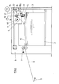
- the sheet feeder on which FIG. 1 is based consists of a portal-shaped frame 1 in which a lifting table 2 for receiving a sheet stack 3 is received so that it can be raised and lowered.
- a suction head 4 which overlaps the sheet stack 3 and which can be adjusted to the rear edge of the stack.
- the suction head 4 is provided with suction cups 5, only one of which is indicated here to simplify the illustration.
- the suction head 4 has a set of suction cups and a set of suction cups.
- the lifting vacuums have the task of lifting the top sheet 6 from the sheet stack 3.
- the drag vacs have the task to take over the respectively lifted sheet 6 and bring it forward so far that it can come into engagement with further transport means 7 arranged in the front area of the frame 1, here in the form of indexing rollers.
- a feed table 8 designed as a bender table, which ends at front marks 9 at which the sheets start with their front edges before they are drawn into a processing machine.
- a cam disk 11 which can be driven by a drive shaft 10 connected to the single-speed shaft and through which the function of the suction cups 5 and the other moving units of the suction head 4 is controlled.
- the suction cups 5 are connected to a vacuum source 13, for example in the form of an installed vacuum network, via a respectively assigned vacuum line 12 and are connected to it in cycles or separated and aerated therefrom.
- a control valve 15 which is arranged in the suction head 4 and is provided with a button 14 resting on the cam plate 11, is provided, by means of which a switching valve 16 arranged close to the suction device can be controlled, via which the vacuum bypass 12 leads.
- This switching valve 16 is designed as a two-way valve through which the vacuum line 12 can be interrupted and a ventilation opening 17 can be opened and vice versa.
- a control line 18 connected to an energy source and guided via the control valve 15 is provided.
- this is designed as a pressure medium line connected to a pressure medium source 19, for example in the form of the installed compressed air network.
- the control line 18 can be branched into a number of branches 18a corresponding to the number of the assigned suction devices 5, each of which leads to an assigned switching valve 16.
- An associated control valve can be provided for each type of suction device, that is to say for the lifting suction devices and for the drag suction devices.
- each suction device or switching valve assigns a separate control valve to each suction device or switching valve.
- a separate switching valve 16 can also be assigned to each suction device or each suction device group.
- each suction valve 5 is to be assigned a switching valve 16 integrated in it, as can best be seen from FIGS. 2 and 3.
- the suction device 5 on which the illustrated embodiment is based is a so-called jumping suction device, which, as shown in FIGS. 2 and 3, consists of a lower part with a suction plate 20, to which a rear sleeve 21 is attached, and of a support rod or a suction head the like.
- the suction plate 20 is supported on the pin 22 by means of a spring 24 and can be lifted off from it by forming an expansion space 25 which is delimited circumferentially by the sleeve 21, into which the through hole 23 opens and from which the suction holes 26 of the suction plate 20 extend.
- the size of this stroke of the lower part of the suction cup is limited by a stop 27 fixed to the upper part and cooperating with a collar of the sleeve 21.
- a branch 28 leads from the through bore 23, which leads to the ventilation opening 17 and which can be opened or blocked as an alternative to the through bore 23, which forms part of the vacuum diversion 12, by means of a switching valve built into the suction cup upper part.
- the housing block 29 of the suction upper part carrying the pin 22 is provided with a valve bore 30 which runs transversely to the through bore 23 and to a branch of the branch 28 parallel thereto and is arranged here coaxially with the ventilation opening 17 and in which a slide 31 is slidably received, which between the the end positions underlying FIGS. 2 and 3 can be moved back and forth.
- This slide 31 has two pistons 33 and 34, which are set apart from one another by a circumferential annular groove 32.
- the slide 31 is pushed into its ventilation position on which FIG. 2 is based by an assigned actuating spring 35, in which the through bore 23 belonging to the vacuum line 12 is interrupted by the piston 33 and the branch 28 leading to the ventilation opening 17 is released.
- the slide 31 is displaced by the pressure medium which can be controlled by means of the control valve 15.
- the associated branch 18a of the control line is connected to the valve bore 30 on the side opposite the spring 35.
- the control edges of the slide 31 and the distances between the through hole 23 and the branch of the branch 28 parallel thereto are matched to one another in such a way that the switching positions mentioned above can be reached. Accordingly, the distance of the said branch of the branch 28 from the end of the valve bore 30 opposite the ventilation opening 17 corresponds at least to the length of the slide 31, so that the ventilation flow path indicated by arrows in FIG. 2 results in the end position of the slide 31 remote from the ventilation opening 17. This is very short due to the arrangement of the ventilation opening 17 inside the sucker.
- the distance of the through bore 23 from the ventilation-side end of the valve bore 30 corresponds at least to the length of the ventilation-side piston 33, so that in the end position on which FIG. 3 is based, the annular groove 32 is congruent comes with the through bore 23 and thus releases the flow path indicated by arrows in FIG. 3.
- the clear width of the annular groove 32 can correspond to the diameter of the through hole 23.
- compressed air taken from the installed compressed air network can be used as pressure medium, which is controlled by the control valve 15, by opening or closing off the control line 18 designed as a compressed air line and venting it downstream of the shut-off.
- the control valve 15 can simply be designed as a two-way valve provided with a ventilation outlet 37. But it would also be conceivable to move the slide 31 electromagnetically.
- the control line could be designed as a power cable and the control valve as a switching relay.
- Vacuum is constantly present in the vacuum line 12.
- pressure medium is constantly present at the control valve 15.
- the slide valve 31 is actuated by corresponding actuation of the control valve 15, it moves into the position on which FIG. 3 is based, in which the bore 23 is separated from the ventilation opening 17 and connected to the vacuum bypass 12, so that the suction plate 20 or whose bores 26 result in a suction that leads to the suction of the uppermost sheet 6 and then to a reduction in the expansion space 25.
- the air volume present when the passage from the bore 23 to the vacuum line 12 is opened below the slide 21 is relatively small, so that the above-mentioned suction results suddenly.
- the slide 31 returns here under the action of the spring 35 to the end position on which FIG. 2 is based, in which the through bore 23 is separated from the vacuum line 12 and connected to the ventilation opening 17 is.
- the line volume below the slide 31, which has to be ventilated, is also very small, so that the ventilation effect also appears suddenly.
- the sheet previously held on the suction plate 20 is released.
- the lower part of the suction cup can be extended under the action of the spring 24, so that the next sheet is sucked in when the next vacuum is applied.
Landscapes
- Engineering & Computer Science (AREA)
- Mechanical Engineering (AREA)
- Sheets, Magazines, And Separation Thereof (AREA)
- Manipulator (AREA)
Applications Claiming Priority (2)
| Application Number | Priority Date | Filing Date | Title |
|---|---|---|---|
| DE4011663A DE4011663C2 (de) | 1990-04-11 | 1990-04-11 | Bogenanleger |
| DE4011663 | 1990-04-11 |
Publications (2)
| Publication Number | Publication Date |
|---|---|
| EP0451702A1 true EP0451702A1 (fr) | 1991-10-16 |
| EP0451702B1 EP0451702B1 (fr) | 1994-06-22 |
Family
ID=6404182
Family Applications (1)
| Application Number | Title | Priority Date | Filing Date |
|---|---|---|---|
| EP91105337A Expired - Lifetime EP0451702B1 (fr) | 1990-04-11 | 1991-04-04 | Margeur |
Country Status (4)
| Country | Link |
|---|---|
| US (1) | US5076564A (fr) |
| EP (1) | EP0451702B1 (fr) |
| JP (1) | JPH0777933B2 (fr) |
| DE (2) | DE4011663C2 (fr) |
Cited By (2)
| Publication number | Priority date | Publication date | Assignee | Title |
|---|---|---|---|---|
| US7825167B2 (en) | 2004-07-14 | 2010-11-02 | 3M Espe Ag | Dental composition containing unsaturated halogenated aryl alkyl ether components |
| CN108750742A (zh) * | 2018-07-18 | 2018-11-06 | 上海暖友实业有限公司 | 发热片送料装置和送料方法 |
Families Citing this family (23)
| Publication number | Priority date | Publication date | Assignee | Title |
|---|---|---|---|---|
| DE4234184C2 (de) * | 1992-10-10 | 1996-02-01 | Heidelberger Druckmasch Ag | Hubsauger zum Anheben eines Papierbogens vom Stapel und zum Halten des Bogens in der angehobenen Position oberhalb des Stapels |
| IT1258331B (it) * | 1992-10-14 | 1996-02-23 | Cefin Spa | Impianto per la distribuzione di aria ad almeno una ventosa facente parte di una macchina operante ad elevata velocita' |
| DE4326927A1 (de) * | 1993-08-11 | 1995-02-16 | Heidelberger Druckmasch Ag | Vorrichtung für Luftsteuerung bei Bogenanlegern von Druckmaschinen |
| US5704673A (en) * | 1994-05-25 | 1998-01-06 | Avery Dennison Corporation | Large area support label carrier |
| DE19543440A1 (de) * | 1995-11-22 | 1997-05-28 | Roland Man Druckmasch | Saug- und/oder Blasluftsteuerung |
| DE19755519C2 (de) * | 1997-12-13 | 2003-11-27 | Koenig & Bauer Ag | Vorrichtung zum Zuführen von Bogen |
| US6299155B1 (en) * | 1998-03-23 | 2001-10-09 | Fuji Photo Film Co., Ltd. | Method of and apparatus for feeding sheets |
| US6311457B1 (en) * | 1999-08-03 | 2001-11-06 | Riverwood International Corporation | Carton feeding method and apparatus |
| AUPR292501A0 (en) * | 2001-02-07 | 2001-03-01 | Silverbrook Research Pty. Ltd. | A method and apparatus (ART100) |
| DE20115549U1 (de) * | 2001-09-21 | 2001-12-06 | FESTO AG & Co., 73734 Esslingen | Vakuumhandhabungsvorrichtung |
| JP2004032001A (ja) | 2002-05-10 | 2004-01-29 | Sony Corp | データ暗号化,復号化もしくは暗号化・復号化方法及び装置 |
| US6820325B2 (en) * | 2002-10-17 | 2004-11-23 | Delaware Capital Formation, Inc. | Integrated air flow control for a pick and place spindle assembly |
| US7276200B2 (en) * | 2003-12-19 | 2007-10-02 | Toyota Motor Engineering & Manufacturing, North America, Inc. | Apparatus and method for removing a part from mold |
| JP4500703B2 (ja) * | 2005-02-18 | 2010-07-14 | 株式会社妙徳 | 吸着ノズル装置 |
| JP4544529B2 (ja) * | 2005-07-29 | 2010-09-15 | セイコーインスツル株式会社 | 真空チャック |
| DE202006005312U1 (de) * | 2006-01-10 | 2006-06-01 | Wohlenberg Buchbindesysteme Gmbh | Vorrichtung zum Abkippen eines Teils einer zu vereinzelnden Signatur von einem Stapel |
| SE530098C2 (sv) * | 2006-07-19 | 2008-03-04 | Xerex Ab | Sätt och anordning varmed alstras och tilll ett ark i en arkmatad tryckpress fördelas ett från atmosfärtryck skilt lufttryck för att verkställa eller påverka arkets transport i tryckpressen |
| JP4976362B2 (ja) * | 2007-10-26 | 2012-07-18 | 株式会社石川製作所 | シート状ワークの送り出し装置及びシート状ワークの送り出し方法 |
| JP5272153B2 (ja) * | 2008-12-26 | 2013-08-28 | キリンテクノシステム株式会社 | プリフォーム用吸着ヘッド、並びにこれを用いたプリフォーム搬送装置及びプリフォーム検査装置 |
| JP5550254B2 (ja) * | 2009-04-23 | 2014-07-16 | 株式会社東芝 | 紙葉類取り出し装置 |
| KR101157542B1 (ko) | 2012-04-26 | 2012-06-22 | 한국뉴매틱(주) | 인-라인 진공펌프 |
| CN205169815U (zh) * | 2013-01-25 | 2016-04-20 | J.施迈茨有限公司 | 面吸气夹持器 |
| JP6609293B2 (ja) * | 2017-08-30 | 2019-11-20 | 平田機工株式会社 | 保持ノズル、保持ヘッド及び移載装置 |
Citations (3)
| Publication number | Priority date | Publication date | Assignee | Title |
|---|---|---|---|---|
| DE2352864B1 (de) * | 1973-10-22 | 1975-03-27 | Roland Offsetmaschf | Steuervorrichtung fuer Blas- und Saugluft an Druckmaschinen |
| GB1398061A (en) * | 1972-04-26 | 1975-06-18 | Heidelberger Druckmasch Ag | Control device for sheet feeders |
| DE2802475A1 (de) * | 1978-01-20 | 1979-07-26 | Windmoeller & Hoelscher | Saugluftsteuerung fuer bogenanlegemaschinen |
Family Cites Families (17)
| Publication number | Priority date | Publication date | Assignee | Title |
|---|---|---|---|---|
| US1418145A (en) * | 1922-01-14 | 1922-05-30 | Fischer Johann | Sheet-ferding device for high-speed printing presses |
| US1625239A (en) * | 1926-04-08 | 1927-04-19 | Hickok W O Mfg Co | Feeding mechanism for ruling machines and the like |
| US1706952A (en) * | 1926-11-19 | 1929-03-26 | W O Hickok Mfg Co | Suction feed roller |
| US1747809A (en) * | 1928-11-09 | 1930-02-18 | Aldrich Lester Kyle | Rotary feeder |
| US1774315A (en) * | 1929-02-21 | 1930-08-26 | Hickok W O Mfg Co | Suction mechanism for sheet feeders |
| US2874962A (en) * | 1953-11-16 | 1959-02-24 | Paul W Layden | Sheet feeding system for printing presses and the like |
| DE1239326B (de) * | 1965-06-18 | 1967-04-27 | Mabeg Maschb G M B H | Anlage zum Erzeugen von Blas- und Saugluft an bogenverarbeitenden Maschinen |
| CH518226A (de) * | 1971-06-11 | 1972-01-31 | Strausak Ag | Einrichtung zur Einzelentnahme blattförmiger Gegenstände von einem Stapel |
| US4090702A (en) * | 1972-04-26 | 1978-05-23 | Heidelberger Druckmaschinen Ag | Suction air control device for use with sheet feeds |
| DE2313514C3 (de) * | 1973-03-19 | 1975-10-09 | Mabeg Maschinenbau Gmbh Nachf. Hense & Pleines Gmbh & Co, 6050 Offenbach. | Bogenvereinzelungsvorrichtung |
| US3999795A (en) * | 1975-12-17 | 1976-12-28 | American Chain & Cable Company, Inc. | Vacuum pad system |
| US4081945A (en) * | 1976-11-15 | 1978-04-04 | The Mead Corporation | Packaging machine for use with cartons of different sizes with minimum adjustment |
| US4175676A (en) * | 1977-09-29 | 1979-11-27 | Goins Jerry D | Apparatus for automatically feeding collar stays |
| US4327906A (en) * | 1978-05-02 | 1982-05-04 | Stahl Gmbh & Co. | Sheet separating apparatus |
| JPS5798442A (en) * | 1980-12-12 | 1982-06-18 | Komori Printing Mach Co Ltd | Sucking head for conveying paper feeder |
| IT1208270B (it) * | 1987-04-08 | 1989-06-12 | Zanasi Nuova Spa | Apparato interruttore parzializzatore dell'aspirazione nelle ventose di alimentazione degli astucci vuoti nelle cosidette astucciatrici automatiche |
| DE3907037C2 (de) * | 1989-03-04 | 1994-03-24 | Heidelberger Druckmasch Ag | Vorrichtung zur Bogenlängenabfrage in einer Bogen bearbeitenden Maschine |
-
1990
- 1990-04-11 DE DE4011663A patent/DE4011663C2/de not_active Expired - Fee Related
-
1991
- 1991-03-19 US US07/671,953 patent/US5076564A/en not_active Expired - Fee Related
- 1991-04-04 EP EP91105337A patent/EP0451702B1/fr not_active Expired - Lifetime
- 1991-04-04 DE DE59101969T patent/DE59101969D1/de not_active Expired - Fee Related
- 1991-04-10 JP JP3077695A patent/JPH0777933B2/ja not_active Expired - Lifetime
Patent Citations (3)
| Publication number | Priority date | Publication date | Assignee | Title |
|---|---|---|---|---|
| GB1398061A (en) * | 1972-04-26 | 1975-06-18 | Heidelberger Druckmasch Ag | Control device for sheet feeders |
| DE2352864B1 (de) * | 1973-10-22 | 1975-03-27 | Roland Offsetmaschf | Steuervorrichtung fuer Blas- und Saugluft an Druckmaschinen |
| DE2802475A1 (de) * | 1978-01-20 | 1979-07-26 | Windmoeller & Hoelscher | Saugluftsteuerung fuer bogenanlegemaschinen |
Cited By (2)
| Publication number | Priority date | Publication date | Assignee | Title |
|---|---|---|---|---|
| US7825167B2 (en) | 2004-07-14 | 2010-11-02 | 3M Espe Ag | Dental composition containing unsaturated halogenated aryl alkyl ether components |
| CN108750742A (zh) * | 2018-07-18 | 2018-11-06 | 上海暖友实业有限公司 | 发热片送料装置和送料方法 |
Also Published As
| Publication number | Publication date |
|---|---|
| JPH0777933B2 (ja) | 1995-08-23 |
| EP0451702B1 (fr) | 1994-06-22 |
| DE4011663C2 (de) | 1994-03-31 |
| JPH04223943A (ja) | 1992-08-13 |
| DE59101969D1 (de) | 1994-07-28 |
| US5076564A (en) | 1991-12-31 |
| DE4011663A1 (de) | 1991-10-17 |
Similar Documents
| Publication | Publication Date | Title |
|---|---|---|
| EP0451702B1 (fr) | Margeur | |
| DE2513769C2 (de) | Saugspannvorrichtung | |
| EP0371974A1 (fr) | Elevateur aspirateur pour convoyeur. | |
| CH414296A (de) | Verfahren und Einrichtung zum gesteuerten intermittierenden Transport eines Bandes | |
| EP0443397B1 (fr) | Margeur de feuilles | |
| CH367437A (de) | Ablege- und Stapelvorrichtung für Tafelmaterial, insbesondere Furniertafeln | |
| DE102009019785B4 (de) | Vorrichtung zum Transportieren von tafelförmigen Gütern | |
| DE4028887C2 (de) | Hydraulische Steuereinrichtung | |
| DE19511296A1 (de) | Vorrichtung zum Anheben und Abtransportieren flächiger Gegenstände | |
| DE2802475C3 (de) | Saugluftsteuerung für Bogenanlegemaschinen | |
| EP0850752B1 (fr) | Presse à étages multiples | |
| DE3709512A1 (de) | Staurollenfoerderer | |
| EP3770445B1 (fr) | Arrangement avec un vérin pneumatique ou hydraulique | |
| DE2710448C2 (de) | Pneumatische Vorrichtung zum Vereinzeln des obersten Bogens eines Bogenstapels | |
| EP1719720B1 (fr) | Dispositif de contrôle pour une ventouse de préhension | |
| DE7626855U1 (de) | Steuerventil | |
| DE3644201C2 (fr) | ||
| DE3902663A1 (de) | Hubsauger fuer eine transporteinrichtung | |
| DE1805410A1 (de) | Zufuehrvorrichtung fuer blattfoermige Materialstuecke | |
| DE102021208274A1 (de) | Membranventil | |
| DE4423653A1 (de) | Vorrichtung zum Anheben und Abtransportieren flächiger Gegenstände | |
| DE1817102A1 (de) | Vorrichtung zur Hubeinstellung und -begrenzung an einer Abkantpresse | |
| DE2914933C2 (de) | Druckmittelbetriebene Fernsteuerung für die pneumatische Hauptsteuereinheit eines Gesenkschmiedehammers, insbesondere eines Gegenschlaghammers | |
| DE10109851A1 (de) | Vorrichtung zum Aufnehmen von Paletten | |
| EP1877331B1 (fr) | Dispositif de commande |
Legal Events
| Date | Code | Title | Description |
|---|---|---|---|
| PUAI | Public reference made under article 153(3) epc to a published international application that has entered the european phase |
Free format text: ORIGINAL CODE: 0009012 |
|
| AK | Designated contracting states |
Kind code of ref document: A1 Designated state(s): CH DE FR GB IT LI SE |
|
| 17P | Request for examination filed |
Effective date: 19920211 |
|
| 17Q | First examination report despatched |
Effective date: 19930827 |
|
| GRAA | (expected) grant |
Free format text: ORIGINAL CODE: 0009210 |
|
| AK | Designated contracting states |
Kind code of ref document: B1 Designated state(s): CH DE FR GB IT LI SE |
|
| PG25 | Lapsed in a contracting state [announced via postgrant information from national office to epo] |
Ref country code: IT Free format text: LAPSE BECAUSE OF FAILURE TO SUBMIT A TRANSLATION OF THE DESCRIPTION OR TO PAY THE FEE WITHIN THE PRESCRIBED TIME-LIMIT;WARNING: LAPSES OF ITALIAN PATENTS WITH EFFECTIVE DATE BEFORE 2007 MAY HAVE OCCURRED AT ANY TIME BEFORE 2007. THE CORRECT EFFECTIVE DATE MAY BE DIFFERENT FROM THE ONE RECORDED. Effective date: 19940622 |
|
| REF | Corresponds to: |
Ref document number: 59101969 Country of ref document: DE Date of ref document: 19940728 |
|
| GBT | Gb: translation of ep patent filed (gb section 77(6)(a)/1977) |
Effective date: 19940805 |
|
| PG25 | Lapsed in a contracting state [announced via postgrant information from national office to epo] |
Ref country code: SE Effective date: 19940922 |
|
| ET | Fr: translation filed | ||
| PGFP | Annual fee paid to national office [announced via postgrant information from national office to epo] |
Ref country code: DE Payment date: 19950315 Year of fee payment: 5 |
|
| PGFP | Annual fee paid to national office [announced via postgrant information from national office to epo] |
Ref country code: CH Payment date: 19950316 Year of fee payment: 5 |
|
| PGFP | Annual fee paid to national office [announced via postgrant information from national office to epo] |
Ref country code: FR Payment date: 19950320 Year of fee payment: 5 Ref country code: GB Payment date: 19950320 Year of fee payment: 5 |
|
| PLBE | No opposition filed within time limit |
Free format text: ORIGINAL CODE: 0009261 |
|
| STAA | Information on the status of an ep patent application or granted ep patent |
Free format text: STATUS: NO OPPOSITION FILED WITHIN TIME LIMIT |
|
| 26N | No opposition filed | ||
| PG25 | Lapsed in a contracting state [announced via postgrant information from national office to epo] |
Ref country code: GB Effective date: 19960404 |
|
| PG25 | Lapsed in a contracting state [announced via postgrant information from national office to epo] |
Ref country code: LI Effective date: 19960430 Ref country code: CH Effective date: 19960430 |
|
| GBPC | Gb: european patent ceased through non-payment of renewal fee |
Effective date: 19960404 |
|
| REG | Reference to a national code |
Ref country code: CH Ref legal event code: PL |
|
| PG25 | Lapsed in a contracting state [announced via postgrant information from national office to epo] |
Ref country code: FR Effective date: 19961227 |
|
| PG25 | Lapsed in a contracting state [announced via postgrant information from national office to epo] |
Ref country code: DE Effective date: 19970101 |
|
| REG | Reference to a national code |
Ref country code: FR Ref legal event code: ST |