EP0451704B1 - Verbesserter Fernsehsignalempfänger - Google Patents
Verbesserter Fernsehsignalempfänger Download PDFInfo
- Publication number
- EP0451704B1 EP0451704B1 EP91105339A EP91105339A EP0451704B1 EP 0451704 B1 EP0451704 B1 EP 0451704B1 EP 91105339 A EP91105339 A EP 91105339A EP 91105339 A EP91105339 A EP 91105339A EP 0451704 B1 EP0451704 B1 EP 0451704B1
- Authority
- EP
- European Patent Office
- Prior art keywords
- television
- signal
- signal receiver
- channel
- receiver
- Prior art date
- Legal status (The legal status is an assumption and is not a legal conclusion. Google has not performed a legal analysis and makes no representation as to the accuracy of the status listed.)
- Expired - Lifetime
Links
- 238000012800 visualization Methods 0.000 claims description 5
- 238000000034 method Methods 0.000 claims description 2
- 230000005236 sound signal Effects 0.000 description 2
- 230000015572 biosynthetic process Effects 0.000 description 1
- 238000010586 diagram Methods 0.000 description 1
- 238000009792 diffusion process Methods 0.000 description 1
- 230000006870 function Effects 0.000 description 1
- 230000001360 synchronised effect Effects 0.000 description 1
- 238000003786 synthesis reaction Methods 0.000 description 1
Images
Classifications
-
- H—ELECTRICITY
- H04—ELECTRIC COMMUNICATION TECHNIQUE
- H04N—PICTORIAL COMMUNICATION, e.g. TELEVISION
- H04N21/00—Selective content distribution, e.g. interactive television or video on demand [VOD]
- H04N21/40—Client devices specifically adapted for the reception of or interaction with content, e.g. set-top-box [STB]; Operations thereof
- H04N21/47—End-user applications
- H04N21/488—Data services, e.g. news ticker
- H04N21/4888—Data services, e.g. news ticker for displaying teletext characters
-
- H—ELECTRICITY
- H04—ELECTRIC COMMUNICATION TECHNIQUE
- H04N—PICTORIAL COMMUNICATION, e.g. TELEVISION
- H04N21/00—Selective content distribution, e.g. interactive television or video on demand [VOD]
- H04N21/40—Client devices specifically adapted for the reception of or interaction with content, e.g. set-top-box [STB]; Operations thereof
- H04N21/47—End-user applications
-
- H—ELECTRICITY
- H04—ELECTRIC COMMUNICATION TECHNIQUE
- H04N—PICTORIAL COMMUNICATION, e.g. TELEVISION
- H04N7/00—Television systems
- H04N7/08—Systems for the simultaneous or sequential transmission of more than one television signal, e.g. additional information signals, the signals occupying wholly or partially the same frequency band, e.g. by time division
- H04N7/087—Systems for the simultaneous or sequential transmission of more than one television signal, e.g. additional information signals, the signals occupying wholly or partially the same frequency band, e.g. by time division with signal insertion during the vertical blanking interval only
- H04N7/088—Systems for the simultaneous or sequential transmission of more than one television signal, e.g. additional information signals, the signals occupying wholly or partially the same frequency band, e.g. by time division with signal insertion during the vertical blanking interval only the inserted signal being digital
- H04N7/0884—Systems for the simultaneous or sequential transmission of more than one television signal, e.g. additional information signals, the signals occupying wholly or partially the same frequency band, e.g. by time division with signal insertion during the vertical blanking interval only the inserted signal being digital for the transmission of additional display-information, e.g. menu for programme or channel selection
Definitions
- the present invention relates to a television signal receiver, comprising receiving means to receive a first television channel and to obtain the relative video signal, destined to be visualized by means of a special image reproducer apparatus, and decoder means to obtain also the eventual televideo signal associated to it.
- It is known television signal receivers that include means to receive a first television channel and to obtain the relative video signal, destined to be visualized by means of special image reproducer apparatus, and also comprising decoder means to obtain the eventual televideo signal (in English called teletext) associated to it.
- Said televideo signal consists of a library of numbered pages that are transmitted in sequence during some lines of the field return in the television signal; said pages are opportunely encoded and for their reception a special decoder is used.
- the decoder allows the visualization of one of the televideo pages, selected by the user between those transmitted, alternately to or superimposed on the normal television image.
- RAI television channels
- the invention is based on the recognition of the fact that it can be useful in certain cases to simultaneously visualize on the screen the television image of a certain channel and a televideo page associated to an other channel.
- the aim of the present invention is therefore to conceive a television signal receiver more flexible than those known, able to satisfy the needs of the user not satisfiable with receivers of the known type.
- the present invention has for its object a television signal receiver as defined in claim 1.
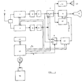
- the reference letter "A” indicates the aerial, connected to the receiver to pickup the available television signals.
- Said aerial is connected to two conventional tuners respectively indicated with the reference numbers 1 and 4; to said tuners follow two signal amplifiers operating on intermediate frequency, also conventional, indicated with the numbers 2 and 5 respectively.
- the amplifier 2 is connected at its out-put to a video detector 3; the amplifier 5, which in its turn, is connected in exit to a video detector 6 and with an amplifier chain and audio signal detector 11.
- the two video detectors 3 and 6 are both connected to a signal manipulator circuit 7 comprising a memory, the so called memory frame, even if at low resolution, in turn connected to a processor 10.
- the circuit 7 is of a known type (for example the part that acts as a signal commutator, can be realized using a TEA integrated circuit 2014) and it is able to combine and to memorize the relative video signals with one or more images and, under the control of the processor 10, comprising a microprocessor circuit of a known type, thus it is possible to send to the successive video amplifier circuit 9, a combined image (commonly said P.I.P. Or Picture in Picture) containing for sample a main image (correspondent to the video signal coming from the chain 4, 5, 6) and a second different image of a reduced size situated in one angle of the first (correspondent to the video signal coming from chain 1, 2, 3).
- a combined image commonly said P.I.P. Or Picture in Picture
- Such combined image is then visualized by the television image reproducer indicated with the letter C, represented for example by a normal colour picture-tube, or other image display of a known type.
- known channel selection means associated both to the main chain ( 4, 5, 6 ) and to the secondary (1, 2, 3), preferably of the type with frequency synthesis with two P.L.L. (for example of the type TSA 5510 from Philips Company), respectively inserted in the tuners 1 and 4 and commanded across the I2C bus of the microprocessor 10.
- the audio signal associated to the main television channel and coming from the circuit 11 reaches a sound reproduction device, referred to by the number 13, that is a conventional sound diffusion system comprising one or more loudspeakers.
- the block 12 represents the ensemble of the synchronism circuits and deflection of the receiver.
- a commutation circuit 8 is also provided, that receives from the circuits 3 and 6 the two video signals, correspondent to the two received television channels; it also receives a control signal E, coming from the microprocessor 10; in exit the circuit 8 is connected to a televideo decoder 14, also connected to the bus of the microprocessor 10, whose exit signal in turn reaches the video amplifier 9.
- the circuit 8 Depending on the signal received, the circuit 8 provides to commute the received televideo signals, sending to the decoder, and so to the picture-tube C, alternately the signal coming from main channel (4, 5, 6) or the signal coming from secondary channel (1, 2, 3).
- the first situation (televideo acquired by the main channel) permits the viewing, as in a normal receiver equipped with televideo function, the television image of the main channel and, alternately or superimposed, the relative televideo pages;
- the second situation (televideo acquired by the secondary channel) permits the viewing of the television image of the main channel and, alternately or superimposed, the televideo pages associated to the secondary channel.
- the reproduced audio will always be that of the main channel.
- the microprocessor receives the suitabable command signals from the user by means of a telecontrol device of the known type (TC/RC); between such command signals there will also be one to decide whether the first or the second televideo signal is to be sent to the televideo decoder 14; such a particular signal will be for example obtained by means of a dedicated button in said telecontrol.
- TC/RC telecontrol device of the known type
- An auxiliary visualization system is also provided, indicated with the reference number 15, that serves to visualize the relative information of the televideo (number of the page required, number of the page received, etc.), particularly useful during the acquirement phase, in the case of the superimposing of a televideo signal taken from a secondary channel on the television image of the main channel.
- the relative information of the televideo number of the page required, number of the page received, etc.
- Such information cannot be visualized in the normal mode, for the incompatibility of the synchronism signals pertinent to the two different television channels.
- Such auxiliary visualization system can consist of a separate conventional display, or can also be obtained with the known O.S.D. method ( On Screen Display ) on the main screen.
Landscapes
- Engineering & Computer Science (AREA)
- Multimedia (AREA)
- Signal Processing (AREA)
- Human Computer Interaction (AREA)
- Television Systems (AREA)
- Two-Way Televisions, Distribution Of Moving Picture Or The Like (AREA)
- Input Circuits Of Receivers And Coupling Of Receivers And Audio Equipment (AREA)
Claims (8)
- Fernsehsignalempfänger, mit:- einer ersten Empfangseinrichtung (4, 5, 6) zum Empfangen eines ersten Fernsehkanals und zum Erhalten von dessen zugehörigem Videosignal;- einer zweiten Empfangseinrichtung (1, 2, 3) zum Empfangen eines zweiten Fernsehkanals und zum Erhalten von dessen zugehörigem Videosignal;- einer Fernsehbildwiedergabevorrichtung (C);- einer ersten Umschalteinrichtung (7) um selektiven Darstellen des entweder von der ersten (4, 5, 6) oder der zweiten Empfangseinrichtung (1, 2, 3) kommenden Videosignals auf der Fernsehbildwiedergabevorrichtung (C);- einer Dekodiereinrichtung (14), um aus einem Videosignal das diesem möglicherweise zugeordnete Videotextsignal zu erhalten;dadurch gekennzeichnet, daß der Fernsehsignalempfänger ebenfalls eine zweite Umschalteinrichtung (8) beinhaltet, um das entweder von der ersten (4, 5, 6) oder zweiten Empfangseinrichtung (1, 2, 3) kommende Videosignal entsprechend einem Befehlssignal (E), welches an die zweite Umschalteinrichtung angelegt ist, selektiv an die Dekodiereinrichtung (14) anzulegen.
- Fernsehsignalempfänger nach Anspruch 1,
dadurch gekennzeichnet, daß das Befehlssignal (E) durch einen Knopf für den Bediener des Empfängers erzeugt wird. - Fernsehsignalempfänger nach Anspruch 1,
dadurch gekennzeichnet, daß das Befehlssignal (E) von einer Fernsteuerung für den Bediener des Empfängers erzeugt wird. - Fernsehsignalempfänger nach Anspruch 1,
dadurch gekennzeichnet, daß die zweite Umschalteinrichtung (8) durch einen Prozessor (10) gesteuert wird. - Fernsehsignalempfänger nach Anspruch 1,
dadurch gekennzeichnet, daß die zweite Umschalteinrichtung (8) der Dekodiereinrichtung (14) während der Periode, in welcher letztere die Daten aufnimmt, die Videosignale sendet, aus welchen die auf der Bildwiedergabevorrichtung (C) anzuzeigenden Videotextsignale extrahiert werden, während, während der Periode, in welcher der Dekodierer (4) schreibt, die zweite Umschalteinrichtung (8) das dem ersten Fernsehkanal zugehörige Videosignal sendet. - Fernsehsignalempfänger nach Anspruch 5,
dadurch gekennzeichnet, daß die Synchronisationssignale für die Ablenkung hinter der ersten Umschalteinrichtung (7) von dem Hauptvideosignal abgegriffen werden. - Fernsehsignalempfänger nach Anspruch 1,
dadurch gekennzeichnet, daß er eine Hilfsdarstellungsvorrichtung (15) zum teilweisen Darstellen der zu den Videotextseiten gehörenden Daten in dem Fall des gleichzeitigen Empfangs von Fernsehbildern von dem ersten Kanal und Videotextbildern von dem zweiten Kanal enthält. - Fernsehsignalempfänger nach Anspruch 7,
dadurch gekennzeichnet, daß die Darstellung der zu den von dem zweiten Kanal entnommenen Videotextbildern gehörenden Daten durch das OSD-Verfahren (On Screen Display) verwirklicht wird.
Applications Claiming Priority (2)
| Application Number | Priority Date | Filing Date | Title |
|---|---|---|---|
| IT67269A IT1240184B (it) | 1990-04-11 | 1990-04-11 | Ricevitore di segnali televisivi perfezionato |
| IT6726990 | 1990-04-11 |
Publications (3)
| Publication Number | Publication Date |
|---|---|
| EP0451704A2 EP0451704A2 (de) | 1991-10-16 |
| EP0451704A3 EP0451704A3 (en) | 1992-09-09 |
| EP0451704B1 true EP0451704B1 (de) | 1996-09-18 |
Family
ID=11301009
Family Applications (1)
| Application Number | Title | Priority Date | Filing Date |
|---|---|---|---|
| EP91105339A Expired - Lifetime EP0451704B1 (de) | 1990-04-11 | 1991-04-04 | Verbesserter Fernsehsignalempfänger |
Country Status (4)
| Country | Link |
|---|---|
| EP (1) | EP0451704B1 (de) |
| DE (1) | DE69122151T2 (de) |
| ES (1) | ES2094165T3 (de) |
| IT (1) | IT1240184B (de) |
Family Cites Families (2)
| Publication number | Priority date | Publication date | Assignee | Title |
|---|---|---|---|---|
| US4677484A (en) * | 1985-05-10 | 1987-06-30 | Rca Corporation | Stabilizing arrangement for on-screen display |
| DE3920119A1 (de) * | 1988-06-20 | 1989-12-21 | Samsung Electronics Co Ltd | Vielkanaleditor vom menue-typ |
-
1990
- 1990-04-11 IT IT67269A patent/IT1240184B/it active IP Right Grant
-
1991
- 1991-04-04 DE DE69122151T patent/DE69122151T2/de not_active Expired - Lifetime
- 1991-04-04 ES ES91105339T patent/ES2094165T3/es not_active Expired - Lifetime
- 1991-04-04 EP EP91105339A patent/EP0451704B1/de not_active Expired - Lifetime
Also Published As
| Publication number | Publication date |
|---|---|
| IT1240184B (it) | 1993-11-27 |
| EP0451704A3 (en) | 1992-09-09 |
| IT9067269A1 (it) | 1991-10-11 |
| DE69122151D1 (de) | 1996-10-24 |
| ES2094165T3 (es) | 1997-01-16 |
| DE69122151T2 (de) | 1997-04-10 |
| EP0451704A2 (de) | 1991-10-16 |
| IT9067269A0 (it) | 1990-04-11 |
Similar Documents
| Publication | Publication Date | Title |
|---|---|---|
| EP0489387B1 (de) | Verbesserter Empfänger für Teletext Übertragungen | |
| US5671019A (en) | Character information display apparatus for a partial and a full-screen display | |
| US4405946A (en) | Television signal converting apparatus providing an on-screen tuning display | |
| JP3326628B2 (ja) | 多重映像テレビ受像機 | |
| KR100320267B1 (ko) | 텔레비젼수상기 | |
| US5315391A (en) | PIP main and subscreen selection from among TV, BS, and VCR playback signals | |
| US6727960B2 (en) | Television channel selection method and apparatus | |
| JPH11220667A (ja) | テレビジョン受像機 | |
| EP0451704B1 (de) | Verbesserter Fernsehsignalempfänger | |
| JPS61145976A (ja) | 車載用テレビ装置 | |
| JPH05336502A (ja) | 映像付加情報挿入装置 | |
| JP2614629B2 (ja) | Catvターミナル | |
| JP3573166B2 (ja) | テレビジョン受信装置およびテレビジョン受信システム | |
| JP3464229B2 (ja) | テレビジョン受信機におけるビデオ信号への制御機能の同期化方法およびその装置 | |
| JPH11225296A (ja) | 映像表示制御装置 | |
| JPH10108083A (ja) | コンピュータシステム | |
| JP2725376B2 (ja) | テレビジョン受像機 | |
| JP2714275B2 (ja) | テレビジョン受像機 | |
| JPH0775034A (ja) | 多信号受信装置 | |
| JPH09149327A (ja) | テレビジョン信号受信装置 | |
| KR0130883B1 (ko) | 멀티 유저 제어방법 및 장치 | |
| JPH06152886A (ja) | 映像信号送信装置および映像信号受信装置 | |
| KR100265233B1 (ko) | Atv의 채널선택방법 및 장치 | |
| JP2538402B2 (ja) | ビデオテ―プレコ―ダ | |
| KR20000028473A (ko) | 영상 기기의 오에스디 처리 장치 |
Legal Events
| Date | Code | Title | Description |
|---|---|---|---|
| PUAI | Public reference made under article 153(3) epc to a published international application that has entered the european phase |
Free format text: ORIGINAL CODE: 0009012 |
|
| AK | Designated contracting states |
Kind code of ref document: A2 Designated state(s): CH DE ES FR GB IT LI NL |
|
| PUAL | Search report despatched |
Free format text: ORIGINAL CODE: 0009013 |
|
| AK | Designated contracting states |
Kind code of ref document: A3 Designated state(s): CH DE ES FR GB IT LI NL |
|
| 17P | Request for examination filed |
Effective date: 19930227 |
|
| 17Q | First examination report despatched |
Effective date: 19950126 |
|
| GRAH | Despatch of communication of intention to grant a patent |
Free format text: ORIGINAL CODE: EPIDOS IGRA |
|
| GRAH | Despatch of communication of intention to grant a patent |
Free format text: ORIGINAL CODE: EPIDOS IGRA |
|
| GRAA | (expected) grant |
Free format text: ORIGINAL CODE: 0009210 |
|
| AK | Designated contracting states |
Kind code of ref document: B1 Designated state(s): CH DE ES FR GB IT LI NL |
|
| PG25 | Lapsed in a contracting state [announced via postgrant information from national office to epo] |
Ref country code: IT Free format text: LAPSE BECAUSE OF FAILURE TO SUBMIT A TRANSLATION OF THE DESCRIPTION OR TO PAY THE FEE WITHIN THE PRE;WARNING: LAPSES OF ITALIAN PATENTS WITH EFFECTIVE DATE BEFORE 2007 MAY HAVE OCCURRED AT ANY TIME BEFORE 2007. THE CORRECT EFFECTIVE DATE MAY BE DIFFERENT FROM THE ONE RECORDED.SCRIBED TIME-LIMIT Effective date: 19960918 Ref country code: LI Effective date: 19960918 Ref country code: CH Effective date: 19960918 |
|
| REF | Corresponds to: |
Ref document number: 69122151 Country of ref document: DE Date of ref document: 19961024 |
|
| ET | Fr: translation filed | ||
| REG | Reference to a national code |
Ref country code: ES Ref legal event code: FG2A Ref document number: 2094165 Country of ref document: ES Kind code of ref document: T3 |
|
| REG | Reference to a national code |
Ref country code: CH Ref legal event code: PL |
|
| PLBE | No opposition filed within time limit |
Free format text: ORIGINAL CODE: 0009261 |
|
| STAA | Information on the status of an ep patent application or granted ep patent |
Free format text: STATUS: NO OPPOSITION FILED WITHIN TIME LIMIT |
|
| 26N | No opposition filed | ||
| REG | Reference to a national code |
Ref country code: GB Ref legal event code: IF02 |
|
| PGFP | Annual fee paid to national office [announced via postgrant information from national office to epo] |
Ref country code: GB Payment date: 20100324 Year of fee payment: 20 |
|
| PGFP | Annual fee paid to national office [announced via postgrant information from national office to epo] |
Ref country code: ES Payment date: 20100423 Year of fee payment: 20 Ref country code: FR Payment date: 20100428 Year of fee payment: 20 |
|
| PGFP | Annual fee paid to national office [announced via postgrant information from national office to epo] |
Ref country code: DE Payment date: 20100511 Year of fee payment: 20 Ref country code: NL Payment date: 20100422 Year of fee payment: 20 |
|
| REG | Reference to a national code |
Ref country code: DE Ref legal event code: R071 Ref document number: 69122151 Country of ref document: DE |
|
| REG | Reference to a national code |
Ref country code: NL Ref legal event code: V4 Effective date: 20110404 |
|
| REG | Reference to a national code |
Ref country code: GB Ref legal event code: PE20 Expiry date: 20110403 |
|
| PG25 | Lapsed in a contracting state [announced via postgrant information from national office to epo] |
Ref country code: GB Free format text: LAPSE BECAUSE OF EXPIRATION OF PROTECTION Effective date: 20110403 Ref country code: NL Free format text: LAPSE BECAUSE OF EXPIRATION OF PROTECTION Effective date: 20110404 |
|
| REG | Reference to a national code |
Ref country code: ES Ref legal event code: FD2A Effective date: 20120511 |
|
| PG25 | Lapsed in a contracting state [announced via postgrant information from national office to epo] |
Ref country code: ES Free format text: LAPSE BECAUSE OF EXPIRATION OF PROTECTION Effective date: 20110405 |
|
| PG25 | Lapsed in a contracting state [announced via postgrant information from national office to epo] |
Ref country code: DE Free format text: LAPSE BECAUSE OF EXPIRATION OF PROTECTION Effective date: 20110404 |