EP0451747B1 - Pétrisseur-mélangeur travaillant en continu - Google Patents
Pétrisseur-mélangeur travaillant en continu Download PDFInfo
- Publication number
- EP0451747B1 EP0451747B1 EP91105497A EP91105497A EP0451747B1 EP 0451747 B1 EP0451747 B1 EP 0451747B1 EP 91105497 A EP91105497 A EP 91105497A EP 91105497 A EP91105497 A EP 91105497A EP 0451747 B1 EP0451747 B1 EP 0451747B1
- Authority
- EP
- European Patent Office
- Prior art keywords
- kneading
- disk
- elements
- bars
- rotation
- Prior art date
- Legal status (The legal status is an assumption and is not a legal conclusion. Google has not performed a legal analysis and makes no representation as to the accuracy of the status listed.)
- Expired - Lifetime
Links
Images






Classifications
-
- B—PERFORMING OPERATIONS; TRANSPORTING
- B01—PHYSICAL OR CHEMICAL PROCESSES OR APPARATUS IN GENERAL
- B01F—MIXING, e.g. DISSOLVING, EMULSIFYING OR DISPERSING
- B01F27/00—Mixers with rotary stirring devices in fixed receptacles; Kneaders
- B01F27/60—Mixers with rotary stirring devices in fixed receptacles; Kneaders with stirrers rotating about a horizontal or inclined axis
- B01F27/70—Mixers with rotary stirring devices in fixed receptacles; Kneaders with stirrers rotating about a horizontal or inclined axis with paddles, blades or arms
- B01F27/707—Mixers with rotary stirring devices in fixed receptacles; Kneaders with stirrers rotating about a horizontal or inclined axis with paddles, blades or arms the paddles co-operating, e.g. intermeshing, with elements on the receptacle wall
Definitions
- the invention relates to a continuously operating mixer kneader for the thermal treatment of products in a liquid, pasty and / or powdery state in a housing, wherein in this housing axially and concentrically arranged a kneader shaft with disk elements and kneading bars and rotating about an axis of rotation is arranged, which causes the transport of the product in the direction of transport, and kneading counter-elements are provided fixedly on the housing between the disc elements, the disc elements also being arranged in disc planes perpendicular to the kneader shaft and forming free sectors between them, which form kneading spaces with the disc plane of adjacent disc elements.
- a generally horizontal mixer kneader normally works with medium product fill levels between 50% and 80%. This makes it possible to supply or remove gases or vapors during the process.
- the inventor has set himself the task of adapting the arrangement of kneading bars on the kneader shaft systematically to a desired axial transport, a desired degree of filling along the kneader and thus a desired residence time and residence time distribution and the intensity of the mixing and kneading action.
- the kneading bars are arranged on a positive or negative offset line in the knee spaces between two disc elements are, with a "positive" offset line each kneading bar assigned to each two disc elements against the direction of rotation followed by a kneading bar assigned to the next two disc elements of the kneading space following in the transport direction, while the "negative" offset line runs in the direction of rotation or transport direction.
- An essential finding of the present invention is that both the transport speed and thus the dwell time of the product in the mixing kneader as well as the intensity of the mixing and kneading effect are significantly influenced by the arrangement of the kneading bars to the disk elements and by the offset of the kneading bars on the kneader shaft. If the kneading bars are arranged on a negative offset line, a disk element pair with a kneading bar in the transport direction and a pair of disk elements without kneading bars follow in the opposite direction of rotation. In this area, both the transport of the product is inhibited and the kneading effect is reduced, since the kneading here is only carried out by the disc elements, possibly in interaction with the kneading counter elements.
- This alternative arrangement of the kneading bars allows the different flow properties of the products to be taken into account; it is even possible to take into account the changing physical states of the product between an inlet and an outlet.
- a stronger or weaker backmixing and consequently a broader or narrower residence time distribution can be used, for example, to influence chemical reaction processes or mixing and kneading processes in the desired manner. For example, short-term dosing fluctuations are compensated for.
- Another possibility is to influence the degree of filling profile along the kneader and e.g. to achieve a lower degree of filling locally under a vapor discharge nozzle, for the purpose of better vapor removal.
- the kneading bars are preferably not located in the middle between two disk elements, but are arranged in front of or behind the disk elements. While the product remains trapped between the disk elements despite the kneading effect of the kneading bar between two disk elements when the kneading bar is arranged, it can adapt to the direction given by the kneading bar when leading or trailing. This can accelerate the transport.
- the number of disk elements which are arranged within a disk plane around the kneader shaft plays only a minor role in the present invention.
- disk elements which have an angular offset of 120 °. However, fewer or more disk elements can also be provided.
- larger free sectors are to be formed between the disk elements, by means of which the axial transport and the mixing are likewise improved in a targeted and desired manner.
- only one disk element per disk level can be present on the kneader shaft.
- the larger non-binding sectors lie on a positive or negative sector line.
- These positive or negative sector lines are arranged analogously to the positive or negative offset lines of the kneading bars. This means that in the case of a negative sector line, the larger free sectors of neighboring knee spaces follow one another in the opposite direction of rotation, opposite to the direction of rotation. In contrast, the larger free sectors on the positive sector line follow each other in the opposite direction of rotation and in the direction of transport.
- the product is transferred from one non-binding sector to another and that of course the transport is accelerated.
- the fastest transport is ensured by combining the arrangement of the kneading bars on a positive offset line and the arrangement of the non-binding sectors on a positive sector line.
- the product transport considerably reduces the arrangement of kneading bars on a negative offset line and the arrangement of sectors on a negative sector line.
- a mix of positive offset line and negative sector line and positive sector and negative offset line is also possible.
- the present invention allows the axial transport behavior and the backmixing (residence time distribution) of a product to be influenced in a desired manner in continuous operation and as a function of the flow behavior.
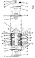
- a mixing kneader has a mostly horizontally arranged housing 1 with end walls 10 and 15.
- a kneader shaft 20 rotates in this housing 1 and is supported with the pins 21 and 22 in the bearings 12 and 17 on both sides of the housing 1.
- a heating jacket for heating the housing is identified by 2.
- the kneader shaft 20 is also preferably heated or cooled in a known manner, with an inlet 29 and an outlet 30 for a heating medium being provided on a corresponding sealing head.
- the kneader shaft 20 is driven by a motor (not shown in more detail) by means of a V-belt placed over a V-belt pulley 23, a transmission 24 being engaged between the V-belt pulley 23 and the kneader shaft 20.
- the mixer kneader shown in Figure 1 is intended for continuous operation.
- the product is filled into the interior of the housing through an inlet nozzle 3 and removed via the outlet nozzle 4.
- various nozzles 5 are provided on the top for removing vapors.
- an overflow weir 32 is provided in a flange connection 31 in front of the outlet connection 4 in the exemplary embodiment of a mixing kneader.
- Disc elements 25 are located on the rotating kneader shaft 20 at regular intervals, each having a disc bar 26 placed thereon. Between the individual sections of disk elements, the disk bars 26 are separated from one another by gaps 34, so that 20 kneading counter-elements 33 can be passed through during operation of the kneader shaft. For this purpose, the kneading counter-elements 33 are inserted into the housing 1 with a flange 35, but can also be welded directly.
- each kneading counter element 33 consists of a fastening flange 35, a neck 36, a kneading arm 37 which extends approximately axially parallel to the housing wall, a disk scraper 38 arranged parallel to the disk elements and a shaft scraper 39 resting on the shaft.
- this is Design of the kneading counter element 33 selected only as an example. Other arrangements are of course also conceivable, as shown for example in CH-A-661 450, EP-A-0 220 575 and DE-A-23 49 106.
- Kneading bars 40 are located on the kneader shaft between the individual levels which are formed by the disk elements 25.
- three disk elements 25a, 25b and 25c are arranged in each disk plane.
- the respective disk bars 26 are set at a certain angle w to an axis-parallel line 41, which means that a transport in the direction x from the inlet nozzle to the outlet nozzle takes place.
- the kneading bars 40 are located between two levels of disk elements 25, two of these levels being indicated by the reference number 42, for example in FIG.
- the kneading bars 40 are located between two disk planes 42 and there in the area between successive disk elements 25, whereby these kneading bars 40 can assume a variable position. In the one position shown, the kneading bars 40 are slightly ahead of two disk elements 25, i.e. close to disk bars 26. These kneading bars are identified in the present exemplary embodiment by 40a.
- the kneading bars 40b are trailing to the disk elements 25, so that they are relatively far away from the disk bars 26 of the following disk elements.
- This possibility of positioning the kneading bars 40 in the region between two disk elements 25a and 25b is characterized in FIG. 2 by the angle ⁇ .
- the displacement of the kneading bars 40 from one kneading space 28 to a next kneading space 28 between two disc planes 42 is important.
- the offset takes place against the direction of rotation z, the offset being referred to here as positive.
- the offset is also indicated by the dash-dotted lines 43. This arrangement accelerates the transport of products in the transport direction x.
- the number of disk elements 25 is three per disk plane 42. With a regular arrangement, this results in an angular offset ⁇ of 120 ° between the disk elements 25.
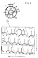
- the arrangement of disk elements 25 and kneading counter-elements 33 is the same as in FIG. 2.
- the two exemplary embodiments differ with regard to the positioning of kneading bars 40 to disk elements 25 or gap 34.
- the kneading bars 40a are here in the kneeling direction, for example successively staggered from the kneading chamber 28 to the kneading chamber 28 in the transport direction x between two disc planes 42. This results in a negative offset line 44, as is indicated by dash-dotted lines.
- the kneading bars 40 are arranged here as leading kneading bars 40a or as trailing kneading bars 40b, which are only shown in broken lines. It can be clearly seen in this embodiment that the transport effect is more negative than in the embodiment according to FIG. 2.
- each kneading bar in the following kneading space 28 between two disk elements is followed by a kneading bar.
- the product is transferred from kneading bars to kneading bars, which speeds up transport.
- a kneading bar 40 in the transport direction x in the following kneading space 28 between two disc planes 42 is followed only by a gap 34 without kneading bars.
- the product is therefore not transferred from kneading bars to kneading bars, which delays the transport.
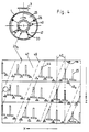
- FIG. 4 A further possibility of assigning kneading bars 40 to disk elements 25 and thus influencing the axial transport, the dwell time and the intensity of the mixing and kneading action is shown in FIG. 4.
- a large number of kneading bars are provided, while one disk element has been left out per disk plane 42.
- the gap which the disk element leaves in the disk plane 42 is referred to as sector 47 and, in this exemplary embodiment, follows one another successively in the direction of rotation z from the kneading chamber 28 to the kneading chamber 28, as represented by the broken line 45. This line is called the negative sector line.
- the offset line 44 of the kneading bars is also negative, so that the transport of the product is considerably reduced in this embodiment.
- two kneading bars 40 are provided in this sector 47.
- a sector 47 is again provided between disk elements 25. However, this sector 47 is now arranged against the direction of rotation z in successive knee spaces 28, so that here there is a positive sector line 46 which has a positive influence on the product transport. The product is passed on from sector to sector, so to speak, when the shaft is rotated in the direction of rotation z.
- the kneading bars are again only provided individually for each sector and are arranged on a negative offset line 44. This means that here the product is on the one hand exposed to positive transport in the sectors and on the other hand to negative transport through the arrangement of the kneading bars 40. It is understandable that this significantly improves and increases the axial mixing and kneading of the product.
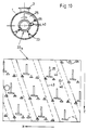
- both the sectors between two disk elements 25 and the kneading bars 40 are located on a positive offset or sector line 43/46. This enables very good evasive movements of the product in the transport direction x, so that the axial transport and at the same time the kneading of the products is influenced very positively.
- the sectors are arranged on a negative sector line 45 in the direction of rotation, while the kneading bars 40 are located on a positive offset line 43.
- the positive offset line 43 accelerates the transport of the product in the transport direction x, but in turn slows it down due to the negative arrangement of the sectors on the sector line 45. This also has a positive effect on a desired kneading or mixing effect.
- a kneader shaft 20f in FIG. 8 two disk elements are omitted for each disk plane 42, specifically in the direction of rotation, i.e. with a negative sector line 45.
- the kneading bars 40 are also arranged on negative offset lines 44.
- the transport of the product in the transport direction x is inhibited twice, because there are always kneading bars or disc elements in the way of the product. Of course, this improves the kneading effect.
- the free cross sections for the axial passage of vapors or gases are larger.
- the sectors are arranged between the disk elements 25 on a positive sector line 46, while the kneading bars 40 are on a negative offset line 44.
- the reduction in the number of kneading bars should also be mentioned here. While three kneading bars were arranged between two disk elements in the embodiment according to FIG. 8, there is only one kneading bar between two disk elements in the embodiment according to FIG. 9, whereby two kneading bars from three successive knee spaces are close to one disk element, while the third kneading bar is located is located in the third kneading chamber approximately exactly between the two remaining disc elements. Despite this reduction in the number of kneading elements, as in all examples, the requirement for extensive self-cleaning in interaction with the static kneading elements is met.
- the exemplary embodiment of the kneader shaft 20h in FIG. 10 is the counterpart to the exemplary embodiment according to FIG. 8, both sectors and kneading bars being provided here on a positive offset line 43 or positive sector line 46. Again, there are three kneading bars between the individual disc elements.
- a kneader shaft 20i is shown in FIG. 11, which represents the counterpart to the kneader shaft 20g in FIG.
- the kneading bars 40 are located on a positive offset line 43 and the sectors between the disk elements 25 are located on a negative sector line 45.
- the positive offset line 43 of the kneading bars improves the product transport, it is again due to the negative arrangement of the sectors on the negative sector line 45 inhibited.
Landscapes
- Chemical & Material Sciences (AREA)
- Chemical Kinetics & Catalysis (AREA)
- Mixers Of The Rotary Stirring Type (AREA)
- Processing And Handling Of Plastics And Other Materials For Molding In General (AREA)
- Preparation Of Clay, And Manufacture Of Mixtures Containing Clay Or Cement (AREA)
- Apparatuses For Bulk Treatment Of Fruits And Vegetables And Apparatuses For Preparing Feeds (AREA)
Claims (11)
- Malaxeur fonctionnant en continu, pour le traitement thermique ou chimique de produits à l'état liquide, pâteux ou pulvérulent dans un carter (1), un arbre (20) de malaxeur s'étendant dans ce carter (1) de façon axiale et concentrique en étant garni d'éléments de disques (25) et de barres (40) du malaxeur et en tournant autour d'un axe de rotation (3), arbre qui provoque le transport du produit dans le sens du transport, et des éléments de contre-malaxage (33) étant prévus de façon fixe sur le carter (1) entre les éléments de disques, tandis qu'en outre les éléments de disques (25) sont disposés dans des plans de disques (42) perpendiculaires à l'arbre du malaxeur et constituent entre eux des secteurs libres (47) qui forment avec les plans de disques (42) d'éléments de disques (25) voisins, des chambres de malaxage (28), malaxeur caractérisé en ce que les barres (40) du malaxeur sont disposées sur une ligne de déport (43 ou 44) positive ou négative dans les chambres de malaxage comprises entre deux plans de disques (42), alors que, dans le cas d'une ligne de déport (43) "positive", chaque barre (40) du malaxeur associée respectivement à deux éléments de disques (25), est suivie, en sens inverse du sens de rotation (z), par une barre de malaxage associée aux deux éléments de disques suivants de la chambre de malaxage qui fait suite dans le sens du transport (x), tandis que la ligne de déport "négative" (44) s'étend dans le sens de rotation (z) et le sens de transport (x).
- Malaxeur selon la revendication 1, caractérisé en ce que les barres (40a) du malaxeur sont disposés dans les chambres de malaxage en précédant respectivement les éléments de disques (25).
- Malaxeur selon la revendication 1, caractérisé en ce que les barres (40b) du malaxeur sont disposées dans les chambres de malaxage en venant respectivement après les éléments de disques (25).
- Malaxeur selon l'une des revendications 1 à 3, caractérisé en ce que l'on prévoit, dans un plan de disques (42), trois éléments de disques (25).
- Malaxeur selon la revendication 4, caractérisé en ce que les éléments de disques (25) sont disposés à l'intérieur d'un plan de disques (42) avec un décalage angulaire de 120°.
- Malaxeur selon l'une des revendications 1 à 3, caractérisé en ce que, dans un plan de disques (42), on dispose au moins un élément de disque (25) de telle façon que les plus grands secteurs (47) restent libres.
- Malaxeur selon la revendication 6, caractérisé en ce que les secteurs les plus grands qui restent libres (47) se trouvent sur une ligne de secteurs positive ou négative(45 ou 46), alors que, dans le cas de la ligne de secteur (46) positive, les secteurs les plus grands (47) des chambres de malaxage les plus voisines se suivent en sens contraire du sens de rotation (z) et dans le sens de transport (x), tandis que la ligne de secteurs négative (45) s'étend dans le sens de rotation (z) et dans le sens de transport (x).
- Malaxeur selon la revendication 7, caractérisé en ce que, dans chaque chambre de malaxage, on associe à chaque élément de disque (25) une barre (40) du malaxeur.
- Malaxeur selon la revendication 8, caractérisé en ce qu'à l'intérieur des plus grands secteurs (47) se trouvent deux barres du malaxeur respectivement voisines(40) auxquelles se raccorde respectivement de façon axiale un élément de disque (25).
- Malaxeur selon la revendication 7, caractérisé en ce que, dans chaque chambre de malaxage (28), on ne prévoit qu'une seule barre (40) du malaxeur, l'une des barres (40) du malaxeur étant disposée entre deux éléments de disques voisins (25), tandis que la barre(40) du malaxeur qui la suit dans le sens de rotation (z), dans le sens du transport x ou dans le sens opposé, se trouve, vue radialement, plus près de l'élément de disque (25) qui suit dans le sens de rotation (z), dans le sens de transport (x) ou en sens inverse, et que la barre (40) du malaxeur qui suit cet élément dans le sens de rotation (z), dans le sens du transport (x) ou en sens inverse est, vue radialement, disposée à proximité d'un autre élément de disque.
- Malaxeur selon au moins l'une des revendications 1 à 10, caractérisé en ce que les dispositions des barres (40) du malaxeur et/ou des secteurs (47) le long de l'arbre de malaxeur (20), sont réalisées et/ou combinées différemment par zones de façon à comprendre respectivement une ou plusieurs sections.
Applications Claiming Priority (2)
| Application Number | Priority Date | Filing Date | Title |
|---|---|---|---|
| CH124490A CH686406A5 (de) | 1990-04-11 | 1990-04-11 | Kontinuierlich arbeitender Mischkneter. |
| CH1244/90 | 1990-04-11 |
Publications (2)
| Publication Number | Publication Date |
|---|---|
| EP0451747A1 EP0451747A1 (fr) | 1991-10-16 |
| EP0451747B1 true EP0451747B1 (fr) | 1995-08-16 |
Family
ID=4205849
Family Applications (1)
| Application Number | Title | Priority Date | Filing Date |
|---|---|---|---|
| EP91105497A Expired - Lifetime EP0451747B1 (fr) | 1990-04-11 | 1991-04-08 | Pétrisseur-mélangeur travaillant en continu |
Country Status (8)
| Country | Link |
|---|---|
| US (1) | US5147135A (fr) |
| EP (1) | EP0451747B1 (fr) |
| JP (1) | JP3225406B2 (fr) |
| AT (1) | ATE126452T1 (fr) |
| CA (1) | CA2040153C (fr) |
| CH (1) | CH686406A5 (fr) |
| DE (1) | DE59106245D1 (fr) |
| ES (1) | ES2077704T3 (fr) |
Cited By (2)
| Publication number | Priority date | Publication date | Assignee | Title |
|---|---|---|---|---|
| US9079984B2 (en) | 2010-06-30 | 2015-07-14 | List Holding Ag | Process for thermal separation of a solution consisting of thermoplastic polymer and solvent |
| US9394626B2 (en) | 2009-08-11 | 2016-07-19 | List Holding Ag | Method for treating a monomer, pre-polymer, polymer or a corresponding mixture |
Families Citing this family (42)
| Publication number | Priority date | Publication date | Assignee | Title |
|---|---|---|---|---|
| CH688365A5 (de) * | 1995-01-18 | 1997-08-29 | List Ag | Misch- und Knetvorrichtung. |
| DE19502571C2 (de) * | 1995-01-27 | 1997-08-07 | Krauss Maffei Ag | Misch- und Knetvorrichtung |
| IL113562A (en) * | 1995-05-01 | 1999-08-17 | Bromine Compounds Ltd | Process for the production of finely granulated solid chemical compounds |
| NL1000276C2 (nl) * | 1995-05-02 | 1996-11-05 | Akzo Nobel Nv | Werkwijze ter vervaardiging van vezels uit poly(p-fenyleen- tereftaalamide). |
| DE19533693A1 (de) * | 1995-09-12 | 1997-03-13 | List Ag | Mischkneter |
| US5873945A (en) * | 1996-05-16 | 1999-02-23 | Nortru, Inc. | Method for recovering a volatile organic material consisting essentially of carbonyl compounds from solvent-in-water emulsions derived from paint overspray treatment and capture systems |
| US6150498A (en) * | 1996-07-12 | 2000-11-21 | The Dow Chemical Company | Polymer recovery |
| US6410783B1 (en) | 2000-10-19 | 2002-06-25 | Basf Corporation | Method of producing carboxylic acid salts |
| CA2445074A1 (fr) * | 2001-04-25 | 2002-11-14 | List Ag | Barres melangeuses a effet nettoyant dans le sens radial ou axial |
| KR100863870B1 (ko) | 2004-06-21 | 2008-10-15 | 에보닉 스톡하우젠 게엠베하 | 수분 흡수성 다당류 및 이의 제조방법 |
| DE102005001802A1 (de) * | 2004-09-30 | 2006-04-06 | List Holding Ag | Verfahren zur kontinuierlichen Durchführung von Polymerisationsprozessen |
| US8361926B2 (en) | 2008-11-25 | 2013-01-29 | Evonik Stockhausen, Llc | Water-absorbing polysaccharide and method for producing the same |
| JP2015509444A (ja) | 2012-02-10 | 2015-03-30 | リスト ホールディング アーゲー | 物理的、化学的及び/又は熱的工程を実行する方法 |
| DE102012110118A1 (de) | 2012-10-24 | 2014-04-24 | List Holding Ag | Verfahren zur Durchführung von mechanischen, chemischen und/oder thermischen Prozessen |
| DE102012103565A1 (de) * | 2012-04-24 | 2013-10-24 | List Holding Ag | Vorrichtung zum Transport von viskosen Massen und Pasten |
| DE102012106239A1 (de) | 2012-07-11 | 2014-01-16 | List Holding Ag | Verfahren und Vorrichtung zur Behandlung eines Produktes |
| DE102012106237A1 (de) | 2012-07-11 | 2014-01-16 | List Holding Ag | Mischkneter zur Behandlung von viskosen bzw. pastösen Produkten in einem Produktraum |
| DE102012108261B4 (de) | 2012-07-11 | 2017-08-03 | List Technology Ag | Mischkneter zur Behandlung von viskosen bzw. pastösen Produkten in einem Produktraum |
| WO2014023738A2 (fr) * | 2012-08-08 | 2014-02-13 | List Holding Ag | Procédé de traitement de masses visco-pâteuses |
| DE102012107255B4 (de) | 2012-08-08 | 2025-02-06 | List Technology Ag | Vorrichtung zur Durchführung von mechanischen, chemischen und/oder thermischen Prozessen in einem Produkt |
| JP2015526579A (ja) * | 2012-09-03 | 2015-09-10 | ビーエーエスエフ ソシエタス・ヨーロピアBasf Se | 芳香族ポリエーテルスルホンの製造方法 |
| DE102013100182A1 (de) * | 2012-09-28 | 2014-06-05 | List Holding Ag | Verfahren zur Durchführung von mechanischen, chemischen und/oder thermischen Prozessen |
| US10442113B2 (en) | 2013-03-04 | 2019-10-15 | List Technology Ag | Method and device for treating viscous, paste-like materials |
| DE102013102570A1 (de) | 2013-03-13 | 2014-09-18 | List Holding Ag | Verfahren zur Aufkonzentration einer Polymerlösung |
| DE102013105566A1 (de) | 2013-05-29 | 2014-12-04 | List Holding Ag | Verfahren zur kontinuierlichen Durchführung einer Polymerisation von Monomeren oder Co-Monomeren |
| DE102014112579A1 (de) | 2013-08-30 | 2015-03-05 | List Holding Ag | Verfahren zum Herstellen einer chemischen Substanz |
| DE102013111066A1 (de) | 2013-10-07 | 2015-04-09 | List Holding Ag | Verfahren zum Herstellen von Halobutyl-Kautschuk |
| DE102014100151A1 (de) | 2014-01-08 | 2015-07-09 | List Holding Ag | Vorrichtung zum Behandeln eines Produktes in einem Gehäuse |
| DE102014004222A1 (de) | 2014-03-25 | 2015-10-01 | List Holding Ag | Verfahren zur Durchführung von mechanischen, chemischen und/oder thermischen Prozessen |
| DE102014106258A1 (de) | 2014-05-06 | 2015-11-12 | List Holding Ag | Vorrichtung zum Bestimmen von mechanischen Belastungszuständen an einer oder mehreren Wellen |
| KR102408877B1 (ko) | 2014-08-13 | 2022-06-13 | 베르살리스 에스.피.에이. | 회전자 및 교반 디바이스 |
| DE102014112268A1 (de) | 2014-08-27 | 2016-03-03 | List Holding Ag | Vorrichtung zum Transport von kompakten Polymermassen |
| WO2016030467A2 (fr) | 2014-08-27 | 2016-03-03 | List Holding Ag | Procédé pour améliorer l'isolation de solutions polymères |
| DE102014113882A1 (de) | 2014-09-25 | 2016-03-31 | List Holding Ag | Vorrichtung zum Transport von kompakten Polymermassen |
| KR102532868B1 (ko) | 2014-11-17 | 2023-05-15 | 리스트 테크놀로지 아게 | 잔류물, 특히 정유공정에서의 잔류물의 처리 및/또는 회수 및/또는 재사용 방법 |
| DE102015106439A1 (de) | 2015-04-27 | 2016-10-27 | List Holding Ag | Verfahren zur Aufbereitung und/oder Rückgewinnung und/oder Wiederverwertung von Rücksänden insbesondere aus Raffinerieprozessen |
| DE102014116757A1 (de) | 2014-11-17 | 2016-05-19 | List Holding Ag | Verfahren zum Aufarbeiten von Rückständen |
| DE102015107027A1 (de) | 2015-05-06 | 2016-11-10 | List Holding Ag | Vorrichtung und Verfahren zur Durchführung von mechanischen, chemischen und/oder thermischen Prozessen |
| DE102015114281A1 (de) | 2015-08-27 | 2017-03-02 | List Holding Ag | Verfahren zur Verbesserung der Isolation von Polymerlösungen |
| DE102017103363A1 (de) | 2017-02-17 | 2018-08-23 | List Technology Ag | Methode zur kontimuierlichen Aufbereitung von im Rahmen der Raffinerie von Rohöl auftretenden Vakuumrückständen |
| CN111442322B (zh) * | 2020-05-13 | 2025-04-08 | 北京首创热力股份有限公司 | 一种供热管网系统及其调控方法 |
| DE102023106828A1 (de) | 2023-03-19 | 2024-09-19 | List Technology Ag | Mischkneter |
Family Cites Families (5)
| Publication number | Priority date | Publication date | Assignee | Title |
|---|---|---|---|---|
| CH583061A5 (fr) * | 1972-10-18 | 1976-12-31 | List Heinz | |
| DE3538070A1 (de) * | 1985-10-25 | 1987-04-30 | Krauss Maffei Ag | Misch- und knetvorrichtung |
| DE3635877C1 (de) * | 1986-10-22 | 1987-10-15 | Heinz Nienhaus | Mischtrockner |
| CH672749A5 (fr) * | 1986-12-19 | 1989-12-29 | List Ag | |
| CH674318A5 (fr) * | 1987-08-28 | 1990-05-31 | List Ag |
-
1990
- 1990-04-11 CH CH124490A patent/CH686406A5/de not_active IP Right Cessation
-
1991
- 1991-04-08 AT AT91105497T patent/ATE126452T1/de not_active IP Right Cessation
- 1991-04-08 EP EP91105497A patent/EP0451747B1/fr not_active Expired - Lifetime
- 1991-04-08 DE DE59106245T patent/DE59106245D1/de not_active Expired - Fee Related
- 1991-04-08 ES ES91105497T patent/ES2077704T3/es not_active Expired - Lifetime
- 1991-04-10 US US07/683,328 patent/US5147135A/en not_active Expired - Lifetime
- 1991-04-10 CA CA002040153A patent/CA2040153C/fr not_active Expired - Fee Related
- 1991-04-11 JP JP07881291A patent/JP3225406B2/ja not_active Expired - Fee Related
Cited By (3)
| Publication number | Priority date | Publication date | Assignee | Title |
|---|---|---|---|---|
| US9394626B2 (en) | 2009-08-11 | 2016-07-19 | List Holding Ag | Method for treating a monomer, pre-polymer, polymer or a corresponding mixture |
| US9079984B2 (en) | 2010-06-30 | 2015-07-14 | List Holding Ag | Process for thermal separation of a solution consisting of thermoplastic polymer and solvent |
| US9480933B2 (en) | 2010-06-30 | 2016-11-01 | List Holding Ag | Process for thermal separation of a solution |
Also Published As
| Publication number | Publication date |
|---|---|
| US5147135A (en) | 1992-09-15 |
| JP3225406B2 (ja) | 2001-11-05 |
| CA2040153C (fr) | 2001-01-02 |
| CH686406A5 (de) | 1996-03-29 |
| DE59106245D1 (de) | 1995-09-21 |
| EP0451747A1 (fr) | 1991-10-16 |
| ES2077704T3 (es) | 1995-12-01 |
| JPH06262049A (ja) | 1994-09-20 |
| ATE126452T1 (de) | 1995-09-15 |
| CA2040153A1 (fr) | 1991-10-12 |
Similar Documents
| Publication | Publication Date | Title |
|---|---|---|
| EP0451747B1 (fr) | Pétrisseur-mélangeur travaillant en continu | |
| EP0517068B1 (fr) | Pétrisseur de mélange | |
| EP0289647B1 (fr) | Pétrin à disques | |
| EP0144092B1 (fr) | Machine pour mélanger et pétrir | |
| DE2349106C2 (de) | Mischkneter | |
| DE2012294C3 (de) | Misch und Knetmaschine | |
| EP0329092A1 (fr) | Mélangeur-pétrin à plusieurs arbres | |
| DE69015577T2 (de) | Apparatus zur Behandlung viskoser Flüssigkeiten. | |
| WO1997012666A1 (fr) | Malaxeur | |
| CH434208A (de) | Misch- und Knetmaschine mit scheibenförmigen Knetelementen | |
| CH686229A5 (de) | Verfahren und Vorrichtung zum kontinuierlichen Netzen von Getreide sowie Verwendung der Netzvorrichtung. | |
| CH661682A5 (de) | Vorrichtung zum bearbeiten von viskosen stoffen bzw. stoffen, die bei der bearbeitung viskos werden. | |
| EP0220575A2 (fr) | Dispositif à mélanger et à pétrir | |
| EP0804278B1 (fr) | Dispositif de melange et de malaxage | |
| CH678285A5 (fr) | ||
| DE3009777C2 (de) | Vorrichtung zum Mischen und Homogenisieren wenigstens zweier Medien | |
| DE19533693A1 (de) | Mischkneter | |
| EP0874724A1 (fr) | Melangeur a plusieurs arbres fonctionnant en continu et destine a des matieres plastifiables | |
| DE1112968B (de) | Vorrichtung zum kontinuierlichen Mischen von Feststoffen mit verfluessigten, vorzugsweise thermoplastischen, insbesondere bituminoesen Bindemitteln | |
| DE2440461C2 (de) | Zwangsmischer für Betonmischmaschinen | |
| DE1546228A1 (de) | Vorrichtung zum Einmischen von Bleichmittel in Zellulosebrei | |
| DE927006C (de) | Verfahren und Vorrichtung zur Herstellung einer feinstbearbeiteten Schokoladenmasse | |
| CH674959A5 (en) | Kneading mixer for thermal and chemical processing - agglomeration of paste is avoided by having two mixing zones and shaft with series of vaned arms which rotate between fixed kneaders | |
| DE2105823A1 (de) | Vorrichtung zum Homogenisieren von Medien | |
| DE2827877C2 (fr) |
Legal Events
| Date | Code | Title | Description |
|---|---|---|---|
| PUAI | Public reference made under article 153(3) epc to a published international application that has entered the european phase |
Free format text: ORIGINAL CODE: 0009012 |
|
| AK | Designated contracting states |
Kind code of ref document: A1 Designated state(s): AT BE DE DK ES FR GB IT LU NL SE |
|
| 17P | Request for examination filed |
Effective date: 19920403 |
|
| 17Q | First examination report despatched |
Effective date: 19931112 |
|
| GRAA | (expected) grant |
Free format text: ORIGINAL CODE: 0009210 |
|
| AK | Designated contracting states |
Kind code of ref document: B1 Designated state(s): AT BE DE DK ES FR GB IT LU NL SE |
|
| PG25 | Lapsed in a contracting state [announced via postgrant information from national office to epo] |
Ref country code: DK Effective date: 19950816 Ref country code: BE Effective date: 19950816 |
|
| REF | Corresponds to: |
Ref document number: 126452 Country of ref document: AT Date of ref document: 19950915 Kind code of ref document: T |
|
| REF | Corresponds to: |
Ref document number: 59106245 Country of ref document: DE Date of ref document: 19950921 |
|
| ITF | It: translation for a ep patent filed | ||
| ET | Fr: translation filed | ||
| GBT | Gb: translation of ep patent filed (gb section 77(6)(a)/1977) |
Effective date: 19951009 |
|
| REG | Reference to a national code |
Ref country code: ES Ref legal event code: FG2A Ref document number: 2077704 Country of ref document: ES Kind code of ref document: T3 |
|
| PG25 | Lapsed in a contracting state [announced via postgrant information from national office to epo] |
Ref country code: LU Free format text: LAPSE BECAUSE OF NON-PAYMENT OF DUE FEES Effective date: 19960430 |
|
| PLBE | No opposition filed within time limit |
Free format text: ORIGINAL CODE: 0009261 |
|
| STAA | Information on the status of an ep patent application or granted ep patent |
Free format text: STATUS: NO OPPOSITION FILED WITHIN TIME LIMIT |
|
| 26N | No opposition filed | ||
| REG | Reference to a national code |
Ref country code: GB Ref legal event code: IF02 |
|
| PGFP | Annual fee paid to national office [announced via postgrant information from national office to epo] |
Ref country code: ES Payment date: 20080429 Year of fee payment: 18 |
|
| PGFP | Annual fee paid to national office [announced via postgrant information from national office to epo] |
Ref country code: AT Payment date: 20080415 Year of fee payment: 18 |
|
| PGFP | Annual fee paid to national office [announced via postgrant information from national office to epo] |
Ref country code: IT Payment date: 20080426 Year of fee payment: 18 |
|
| PGFP | Annual fee paid to national office [announced via postgrant information from national office to epo] |
Ref country code: NL Payment date: 20080415 Year of fee payment: 18 Ref country code: SE Payment date: 20080414 Year of fee payment: 18 Ref country code: DE Payment date: 20080627 Year of fee payment: 18 |
|
| PGFP | Annual fee paid to national office [announced via postgrant information from national office to epo] |
Ref country code: FR Payment date: 20080412 Year of fee payment: 18 |
|
| PGFP | Annual fee paid to national office [announced via postgrant information from national office to epo] |
Ref country code: GB Payment date: 20080421 Year of fee payment: 18 |
|
| EUG | Se: european patent has lapsed | ||
| GBPC | Gb: european patent ceased through non-payment of renewal fee |
Effective date: 20090408 |
|
| NLV4 | Nl: lapsed or anulled due to non-payment of the annual fee |
Effective date: 20091101 |
|
| REG | Reference to a national code |
Ref country code: FR Ref legal event code: ST Effective date: 20091231 |
|
| PG25 | Lapsed in a contracting state [announced via postgrant information from national office to epo] |
Ref country code: DE Free format text: LAPSE BECAUSE OF NON-PAYMENT OF DUE FEES Effective date: 20091103 Ref country code: AT Free format text: LAPSE BECAUSE OF NON-PAYMENT OF DUE FEES Effective date: 20090408 |
|
| PG25 | Lapsed in a contracting state [announced via postgrant information from national office to epo] |
Ref country code: NL Free format text: LAPSE BECAUSE OF NON-PAYMENT OF DUE FEES Effective date: 20091101 |
|
| PG25 | Lapsed in a contracting state [announced via postgrant information from national office to epo] |
Ref country code: FR Free format text: LAPSE BECAUSE OF NON-PAYMENT OF DUE FEES Effective date: 20091222 Ref country code: GB Free format text: LAPSE BECAUSE OF NON-PAYMENT OF DUE FEES Effective date: 20090408 |
|
| REG | Reference to a national code |
Ref country code: ES Ref legal event code: FD2A Effective date: 20090411 |
|
| PG25 | Lapsed in a contracting state [announced via postgrant information from national office to epo] |
Ref country code: ES Free format text: LAPSE BECAUSE OF NON-PAYMENT OF DUE FEES Effective date: 20090411 |
|
| PG25 | Lapsed in a contracting state [announced via postgrant information from national office to epo] |
Ref country code: IT Free format text: LAPSE BECAUSE OF NON-PAYMENT OF DUE FEES Effective date: 20090408 |
|
| PG25 | Lapsed in a contracting state [announced via postgrant information from national office to epo] |
Ref country code: SE Free format text: LAPSE BECAUSE OF NON-PAYMENT OF DUE FEES Effective date: 20090409 |