EP0451868B1 - Douche - Google Patents
Douche Download PDFInfo
- Publication number
- EP0451868B1 EP0451868B1 EP91105882A EP91105882A EP0451868B1 EP 0451868 B1 EP0451868 B1 EP 0451868B1 EP 91105882 A EP91105882 A EP 91105882A EP 91105882 A EP91105882 A EP 91105882A EP 0451868 B1 EP0451868 B1 EP 0451868B1
- Authority
- EP
- European Patent Office
- Prior art keywords
- solution
- chamber
- pressure reducing
- hole
- adjusting
- Prior art date
- Legal status (The legal status is an assumption and is not a legal conclusion. Google has not performed a legal analysis and makes no representation as to the accuracy of the status listed.)
- Expired - Lifetime
Links
- 238000003287 bathing Methods 0.000 title claims description 42
- XLYOFNOQVPJJNP-UHFFFAOYSA-N water Substances O XLYOFNOQVPJJNP-UHFFFAOYSA-N 0.000 claims description 67
- 230000001603 reducing effect Effects 0.000 claims description 42
- 239000003570 air Substances 0.000 claims description 30
- 239000012080 ambient air Substances 0.000 claims description 5
- 239000008155 medical solution Substances 0.000 description 43
- 239000000243 solution Substances 0.000 description 30
- 239000003814 drug Substances 0.000 description 27
- 239000000945 filler Substances 0.000 description 8
- 239000007788 liquid Substances 0.000 description 5
- 239000000654 additive Substances 0.000 description 4
- 230000000996 additive effect Effects 0.000 description 4
- 230000000694 effects Effects 0.000 description 3
- 239000007787 solid Substances 0.000 description 3
- 229940126589 solid medicine Drugs 0.000 description 3
- XAGFODPZIPBFFR-UHFFFAOYSA-N aluminium Chemical compound [Al] XAGFODPZIPBFFR-UHFFFAOYSA-N 0.000 description 2
- 229910052782 aluminium Inorganic materials 0.000 description 2
- 239000004411 aluminium Substances 0.000 description 2
- 229940079593 drug Drugs 0.000 description 2
- -1 abluents Substances 0.000 description 1
- 239000003795 chemical substances by application Substances 0.000 description 1
- 239000003974 emollient agent Substances 0.000 description 1
- 239000002304 perfume Substances 0.000 description 1
- 239000004033 plastic Substances 0.000 description 1
- 239000000843 powder Substances 0.000 description 1
- 230000000630 rising effect Effects 0.000 description 1
- 239000002453 shampoo Substances 0.000 description 1
- 239000000344 soap Substances 0.000 description 1
- 238000003756 stirring Methods 0.000 description 1
- 239000012780 transparent material Substances 0.000 description 1
Images


Classifications
-
- B—PERFORMING OPERATIONS; TRANSPORTING
- B05—SPRAYING OR ATOMISING IN GENERAL; APPLYING FLUENT MATERIALS TO SURFACES, IN GENERAL
- B05B—SPRAYING APPARATUS; ATOMISING APPARATUS; NOZZLES
- B05B7/00—Spraying apparatus for discharge of liquids or other fluent materials from two or more sources, e.g. of liquid and air, of powder and gas
- B05B7/24—Spraying apparatus for discharge of liquids or other fluent materials from two or more sources, e.g. of liquid and air, of powder and gas with means, e.g. a container, for supplying liquid or other fluent material to a discharge device
- B05B7/2402—Apparatus to be carried on or by a person, e.g. by hand; Apparatus comprising containers fixed to the discharge device
- B05B7/244—Apparatus to be carried on or by a person, e.g. by hand; Apparatus comprising containers fixed to the discharge device using carrying liquid for feeding, e.g. by suction, pressure or dissolution, a carried liquid from the container to the nozzle
- B05B7/2443—Apparatus to be carried on or by a person, e.g. by hand; Apparatus comprising containers fixed to the discharge device using carrying liquid for feeding, e.g. by suction, pressure or dissolution, a carried liquid from the container to the nozzle the carried liquid and the main stream of carrying liquid being brought together downstream of the container before discharge
-
- E—FIXED CONSTRUCTIONS
- E03—WATER SUPPLY; SEWERAGE
- E03C—DOMESTIC PLUMBING INSTALLATIONS FOR FRESH WATER OR WASTE WATER; SINKS
- E03C1/00—Domestic plumbing installations for fresh water or waste water; Sinks
- E03C1/02—Plumbing installations for fresh water
- E03C1/04—Water-basin installations specially adapted to wash-basins or baths
- E03C1/046—Adding soap, disinfectant, or the like in the supply line or at the water outlet
Definitions
- the present invention relates to a shower bathing device capable of making users enjoy bathing hot water showered and also capable of mixing solution for medical or other purposes with hot water showered and freely adjusting the amount of the medical solution mixed.
- the conventional shower bathing device was intended only to shower hot water. Recently, however, shower bathing device having a section in which a medicine is filled and another section located on the passage of hot water to mix the medicine with hot water passing through the passage has been proposed (Japanese Utility Model Disclosures Sho 61-155054, -40153, -40154, Sho 62-144562, -194450, Japanese Patent Disclosure Hei 1-223915, Japanese Patent Publication Sho 44-5583 and others).
- This shower bathing device is intended to fill the medical section with a desired medicine and shower through the head of the shower bathing device (or shower head) hot water while mixing hot water with the medicine.
- the medicine used may be of the solid type and of the solution type.
- the medicine of the solid type is used on the passage of hot water, however, it often happens that the solid medicine is instantly dissolved or not dissolved by hot water passing through the passage. This makes it difficult to adjust the amount of the solid medicine dissolved into hot water.
- the solid medicine can be easily dissolved when the temperature of hot water passing through the passage is high but not when it is low. Therefore, users cannot enjoy bathing hot water which is showered through the shower bathing device and in which the medicine is contained at such an amount as desired.
- the medicine used is of the solution type.
- the medicine cannot be mixed with hot water only by providing both of the medicine-filled section and the water-medicine mixing section on the passage of hot water.
- the pressure of hot water passing through the passage is applied to the medicine-filled section to thereby make it impossible to mix the medicine with hot water. It is impossible to mix the medicine with hot water unless the water-medicine mixing section is under pressure-reduced state.
- Japanese Utility Model Disclosure Sho 62-194450 discloses a structure wherein medicine is mixed with hot water by a stream pump system. However, it discloses neither system nor means for adjusting the amount of the bath medicine mixed. In short, it discloses only a valve located between a bath medicine tank and the passage of hot water in this case, but this valve cannot change the pressure-reduced state in the water-medicine mixing section, thereby making it impossible to finely adjust the amount of the medicine mixed with hot water.
- Japanese Patent Disclosure Hei 1-223915 discloses another structure wherein the flow rate of bath medicine is controlled by an adjusting cock means. This cock means, however, is attached to the same position as the valve is in the above case. Therefore, the flow rate of bath medicine cannot be finely adjusted by the adjusting cock means.
- Japanese Patent Publication Sho 44-5583 discloses further structure wherein an opening is formed at the section of the stream pump.
- this opening is intended not to adjust the flow rate of bath medicine but to mix air with hot water passing through the passage. Therefore, the opening has no means for adjusting the extent to which the opening is opened.
- FR-A-2356 400 discloses a shower bathing device which includes a flexible hose, a shower head, and a solution admixing device coupled between the flexible hose and the shower head.
- the solution admixing device has a tubular body with threads on opposite ends thereof for receiving the hose and the shower head, respectively, and a lateral tubular projection forming a chamber for receiving a plastic bag filled with solution.
- a short pointed tube projects into the chamber to perforate the bag so that its contents can flow to a mixing chamber of a jet pump formed in the body.
- a projection on the opposite side of the chamber forms a channel which connects the mixing chamber with the ambient air.
- a cap is screwed on the projection to adjust the amount of ambient air and, thus, the amount of solution which is supplied to the mixing chamber.
- FR-A-2 380 761 discloses a shower bathing device which contains a stream pump in a rising tube leading from a water supply to a shower head.
- a lateral tube connects the stream pump with a vessel containing a solution to be admixed to the water supplied to the shower head.
- the amount of solution supplied can be adjusted by a valve in the lateral tube or in a bypass of the stream pump or in an extension of the lateral tube leading to the ambient air.
- US-A-4 623 095 discloses a device to air entrain and add liquid soap or some other liquid additive to a water stream which flows through a shower head. There is a secondary liquid additive passageway leading into a constricted reduced pressure area of the main flow passageway of the shower water.
- a funnel-like container, in which the liquid additive is poured, is mounted laterally and rotably on the water conduit. The supply of the liquid additive can be shut off by rotating the container.
- a shower bathing device comprising a shower head having passage means through which water is passed, a solution chamber for receiving a member filled with a solution to be supplied into the passage means, means for mixing the solution with water passing through the passage means, said mixing means including stream pump means arranged in the way of the passage means, a pressure reducing chamber communicated with the stream pump means and with ambient air, a mixing area formed in the pressure reducing chamber and communicating with the solution chamber, and means for adjusting the amount of the solution supplied to the mixing area by adjusting the amount of air entering from outside into the pressure reducing chamber, and means for breaking a seal of said solution-filled member, said breaking means projecting into said solution chamber and communicating with the mixing area to supply the solution in the solution-filled member to the mixing area, is characterized according to the present invention in that said mixing means and said solution chamber are formed in said shower head and said solution-filled member is detachably seated on a disk of said solution chamber from which said breaking means projects.
- the shower bathing device of the present invention is compact, convenient to use and makes it possible to mix the solution of any of desired medicines such as bath solutions, shampoo, hair rinsing agents, perfumes, abluents, emollient agents, and wound medicines into hot water.
- the shower bathing device can create such hot water that has any intended effect.
- the amount of the solution mixed with hot water can be adjusted to thereby achieve more prominent effect which was not seen in the conventional cases.
- the solution filled in the solution chamber is of the solid or powder type, it can be used in solution to achieve the same effect after it is diffused into water or oil. This makes it possible for the shower bathing device to use almost all of the solution.
- Fig. 1 schematically shows the main portion of a shower bathing device according to the present invention and Fig. 2 shows the whole of the shower bathing device.
- a hot water passage 2 is formed in a head 1 of the shower bathing device and a stream pump 3 is arranged enclosing the hot water passage 2.
- the stream pump 3 is provided with a pressure reducing chamber 4.
- Another chamber 5 which is filled with medical solution is also formed in the shower head 1 along the hot water passage 2.
- An area 6 where the medical solution and hot water are mixed is formed in the pressure reducing chamber 4 and this mixing area 6 is communicated with the medical-solution-filled chamber 5 through a medical solution passage 7.
- the pressure reducing chamber 4 is further provided with a through-hole 8 communicated with outside, and a member 9 (or a screw in this case) for adjusting the amount of air allowed to enter into the pressure reducing chamber 4 is inserted into the through-hole 8 so as to adjust that open area of the through-hole 8 through which air is allowed to enter into the pressure reducing chamber 4.
- the through-hole 8 is adjusted by the air adjusting member 9, that is, the open area of the through-hole 8 through which the pressure reducing chamber 4 is communicated with air outside is adjusted by the air adjusting member 9.
- the pressure reducing extent of hot water in the chamber 4, or the amount of air allowed to enter into the chamber 4, or the amount of the medical solution pulled into the chamber 4 is adjusted.
- the medical-solution-filled chamber 5 is made of transparent material so as to enable it to be confirmed by eyes how much the medical solution is mixed into hot water in the pressure reducing chamber 4.
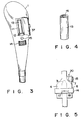
- Fig. 3 shows the shower bathing device according to another embodiment of the present invention.
- a medical solution chamber 11 is formed in the shower head 1 and it can be opened and closed by a swing door member 37. It also includes a disk 12 at the bottom thereof, on which a filler member 13 of the cassette type which is filled with the medical solution is seated.
- Reference numeral 14 in Fig. 3 denotes an adjusting dial which is arranged, rotatable, enclosing the pressure reducing chamber 4 to adjust the amount of the medical solution pulled into and mixed with hot water in the pressure reducing chamber 4.
- Another reference numeral 15 represents a cock for opening and closing the medical solution passage 7. The medical solution in the filler member 13 can be prevented from leaking outside if the medical solution passage 7 is closed by the cock 15 when the viscosity of the medical solution is very low and the shower bathing device is left unused.
- Figs. 4 and 5 are intended to explain how the shower bathing device in Fig. 3 is operated.
- Fig. 4 shows the filler member 13 of the cassette type which is filled with the medical solution and which is sealed by an aluminium seal 16.
- Fig. 5 schematically shows the body portion of the shower head so arranged as to receive the filler member 13, wherein a cylindrical needle 20 is projected from the medical solution passage 7 communicated with the mixing area 6 and the aluminium seal 16 of the filler member 13 is broken by this needle 20 when the filler member 13 is seated on the disk 12 in the filler chamber 11. As the result, the medical solution in the filler member 13 is allowed to flow into the mixing area 6 through the medical solution passage 7.
- the adjusting dial 14 is provided with a circular air hole 17, and a through-hole 18 which is shaped like a water drop, widening more and more as it comes nearer to the bottom of the water drop, is formed at the wall of the pressure reducing chamber 4.
- the amount of air allowed to enter into the pressure reducing chamber 4 can be therefore adjusted depending on what part of the water-drop-shaped hole 18 the air hole 17 is superposed, that is, by the open area which is formed by both of the circular air hole 17 and the water-drop-shaped hole 18 and through which the pressure reducing chamber 4 is communicated with air outside.
- the present invention has been applied to the shower head in the above-described cases, it may be applied to any point on the hot water passage and same merits can also be achieved in this case.
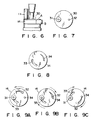
- Fig. 6 shows the flow rate adjusting system according to another embodiment of the present invention.
- Fig. 7 is a plan showing a section A which is included in the flow rate adjusting system shown in Fig. 6.
- the section A is a disk 30 fixed to the shower head 1 and provided with a circular through-hole 31 through which the medical solution is allowed to enter into the pressure reducing chamber 4 and also provided with a circular through-hole 32 through which air outside is allowed to enter into the chamber 4.
- Fig. 8 is a plan showing a section B which is included in the flow rate adjusting system shown in Fig. 6.
- the section B is the adjusting dial 14 provided with an arc slot 33 for adjusting the amount of the medical solution allowed to enter into the pressure reducing chamber 4 and also provided with an arc slot 34 which becomes wider and wider from one end to the other end thereof to adjust the amount of air allowed to enter into the chamber 4.
- These slots 33 and 34 of the adjusting dial 14 are positioned to correspond to the through-holes 31 and 32 of the disk 30.
- the through-hole 31 is not superposed on the medical solution adjusting slot 33 to thereby stop the supply of the medical solution into hot water in the pressure reducing chamber 4.
- the through-hole 32 is not superposed on the air adjusting slot 34.
- the amount of air adjusted therefore, becomes maximum and the force created by the stream pump 3 to pull the medical solution into the pressure reducing chamber 4 becomes minimum. Neither the medical solution nor air outside is allowed to enter into the pressure reducing chamber 4, accordingly.
- the through-hole 31 is communicated with the medical solution adjusting slot 33 while the through-hole 32 is also communicated with the air adjusting slot 34 through the maximum open sectional area. Therefore, the amount of air is a little adjusted and the solution pulling force created by the stream pump 3 is a little increased, so that a little amount of the medical solution can be mixed with hot water in the pressure reducing chamber 4.
- the adjusting dial 14 is positioned as shown in Fig.
- the open sectional area of a hole which is formed when both of the through-hole 31 and the medical solution adjusting slot 33 are superposed one upon the other is same as in the case shown in Fig. 9B but the open sectional area of another hole formed when both of the through-hole 32 and the air adjusting slot 34 are superposed one upon the other is made smaller. Therefore, the air adjusting hole is made smaller while leaving the medical solution supply opening open.
- the medical solution pulling force is thus increased to allow a larger amount of the medical solution to be mixed with hot water in the pressure reducing chamber 4.
- the amount of the medical solution allowed to enter into the chamber 4 can be finely adjusted by one dial in this manner.
- Figs. 10 and 11 show the shower bathing devices according to further embodiments of the present invention, wherein the function of showering hot water in which the medical solution is mixed is further enhanced.
- Each of these devices is provided with a small hole 35 through which the hot water passage 2 is communicated with the pressure reducing chamber 4 to allow hot water in the hot water passage to enter into the chamber 4. It is preferable that the size of this small hole 35 is so large as not to extremely lower the pressure reducing action of the stream pump 3.
- the shower bathing device has the small hole 35
- the medical solution while being entered into the pressure reducing chamber 4 by the action of the stream pump 3, is violently stirred and mixed with hot water in the pressure reducing chamber 4 by hot water entering into the chamber 4 through the small hole 35, and the hot water thus mixed with the medical solution is then allowed to flow into the hot water passage.
- the device has no small hole 35
- the small hole 35 is formed as shown in Figs. 10 and 11
- hot water entering into the pressure reducing chamber 4 through the small hole 35 stirs the medical solution.
- hot water showered through the shower head can have a desirable amount of the medicine therein, depending on the extent to which the through-hole 8 is opened or closed.
- the chamber 5 which is filled with the medical solution may have a small air hole 36 through which it can be communicated with air outside.
- the pressure in the chamber 5 can be kept same as atmospheric pressure by this small air hole 36 to thereby enable the medical solution to be mixed with hot water in the pressure reducing chamber 4 under steady state.
Landscapes
- Health & Medical Sciences (AREA)
- Life Sciences & Earth Sciences (AREA)
- Engineering & Computer Science (AREA)
- Hydrology & Water Resources (AREA)
- Public Health (AREA)
- Water Supply & Treatment (AREA)
- Bathtubs, Showers, And Their Attachments (AREA)
- Nozzles (AREA)
Claims (5)
- Douche comprenant :a) une pomme (1) de douche comportant un moyen formant un passage (2) à travers lequel passe de l'eau;b) une chambre (11) à solution destinée à recevoir un élément (13) rempli d'une solution devant être introduite dans le passage (2);c) un moyen pour mélanger la solution avec l'eau passant par le passage (2), ledit moyen de mélange comprenant un moyen formant une pompe à jet (3) disposée sur le chemin du passage (2), une chambre (4) de réduction de pression, commnuniquant avec la pompe à jet (3) et avec l'air ambiant, une zone de mélange formée dans la chambre (4) de réduction de pression et communiquant avec la chambre (5) à solution, et des moyens (8, 9) pour régler la quantité de la solution fournie à la zone de mélange (6) par ajustement de la quantité d'air pénétrant depuis l'extérieur dans la chambre (4) de réduction pression, etd) un moyen (20) pour rompre un opercule d'étanchéité (16) dudit élément rempli de solution, ledit moyen de rupture faisant saillie dans la chambre (11) à solution et communiquant avec la zone de mélange (6) pour fournir à la zone de mélange (6) la solution se trouvant dans l'élément (13) rempli de solution.caractérisée en ce que ledit moyen de mélange (3, 4, 6, 8, 9) et ladite chambre (5) à solution sont formés dans ladite pomme (1) de douche et ledit élément (13) rempli de solution repose de façon séparable sur un disque (12) que comporte la chambre à solution et à partir duquel ledit moyen de rupture (20) fait saillie.
- Douche selon la revendication 1, caractérisée en ce que ledit moyen de réglage comprend un trou traversant (18) formé dans la paroi de la chambre (4) de réduction de pression, un élément formant un bouton de réglage (14) disposé de façon à pouvoir tourner autour de la chambre (4) de réduction de pression et un trou traversant (17) formé dans le bouton de réglage (14), les trous traversants (17) et (18) étant positionnés de manière à se superposer lorsque l'on fait tourner le bouton de réglage (14) et étant tous deux configurés d'une façon différente telle l'un par rapport à l'autre qu'ils modifient la superficie d'ouverture du trou formé quand ils se superposent lorsque l'on fait tourner le bouton de réglage (14).
- Douche selon la revendication 2, caractérisée en ce que l'un des trous traversants (17) et (18) a une forme circulaire et l'autre de ces trous a une forme analogue à une goutte d'eau, s'élargissant de plus en plus d'une de ses extrémités à l'autre.
- Douche selon la revendication 1, caractérisée en ce que ledit moyen de réglage comprend un élément formant une plaque (30) interposée entre la chambre (5) et la zone de mélange (6) et pourvue d'un trou traversant (31) de réglage de solution communiquant avec la chambre (5) et d'un trou traversant (32) débouchant vers l'extérieur, et un élément formant un bouton de réglage (14) disposé de manière à pouvoir tourner autour de la chambre (4) de réduction de pression et pourvu d'un trou traversant (33) de réglage de solution et d'un trou traversant (34) de passage d'air, les trous traversants (31) et (33) de la chambre (5) et du bouton de réglage (14) étant positionnés de manière à se superposer lorsque l'on fait tourner le bouton de réglage (14), et les trous traversants (32) et (34) de la chambre (5) et du bouton de réglage (14) étant positionnés de manière à être mis en communication et à se fermer lorsque l'on fait tourner le bouton de réglage (14) tout en étant tous deux configurés d'une façon différente telle l'un par rapport à l'autre qu'ils modifient la superficie d'ouverture du trou formé quand ils se superposent lorsque l'on fait tourner le bouton de réglage (14).
- Douche selon la revendication 1, comprenant en outre un moyen (35) pour faire communiquer le passage (2) avec la chambre (4) de réduction de pression.
Applications Claiming Priority (2)
| Application Number | Priority Date | Filing Date | Title |
|---|---|---|---|
| JP3903090 | 1990-04-13 | ||
| JP39030/90U | 1990-04-13 |
Publications (3)
| Publication Number | Publication Date |
|---|---|
| EP0451868A2 EP0451868A2 (fr) | 1991-10-16 |
| EP0451868A3 EP0451868A3 (en) | 1992-01-02 |
| EP0451868B1 true EP0451868B1 (fr) | 1994-11-09 |
Family
ID=12541714
Family Applications (1)
| Application Number | Title | Priority Date | Filing Date |
|---|---|---|---|
| EP91105882A Expired - Lifetime EP0451868B1 (fr) | 1990-04-13 | 1991-04-12 | Douche |
Country Status (3)
| Country | Link |
|---|---|
| US (1) | US5305476A (fr) |
| EP (1) | EP0451868B1 (fr) |
| DE (1) | DE69105027T2 (fr) |
Cited By (1)
| Publication number | Priority date | Publication date | Assignee | Title |
|---|---|---|---|---|
| US8616469B2 (en) | 2009-06-15 | 2013-12-31 | Kosdo, Inc. | Water-saving shower head with extension utilizing air-pressure |
Families Citing this family (23)
| Publication number | Priority date | Publication date | Assignee | Title |
|---|---|---|---|---|
| US5562248A (en) * | 1994-12-27 | 1996-10-08 | Khalifka; Mahmound | Showerhead with integrated soap dispenser |
| USD390915S (en) | 1996-12-06 | 1998-02-17 | Waxman Consumer Products Group Inc. | Sink sprayer |
| US5906316A (en) * | 1997-09-04 | 1999-05-25 | S. C. Johnson & Son, Inc. | Nozzle to dispense active material |
| US5893519A (en) * | 1997-09-12 | 1999-04-13 | Cavaretta; Kenneth L. | Self-educting, high expansion, multi-agent nozzle |
| US6000626A (en) * | 1998-01-12 | 1999-12-14 | Waxman Consumer Products Group, Inc. | Hand operated water sprayer and soap dispenser |
| US5991937A (en) * | 1998-03-10 | 1999-11-30 | Safara; Stephen G | Bidet device |
| US6006374A (en) * | 1998-09-23 | 1999-12-28 | Winnett; Harold G. | Showerhead attachment and method for generating aromas |
| US6186988B1 (en) | 1999-04-05 | 2001-02-13 | Kenneth A Sabacinski | Wound irrigation system |
| DE19929359A1 (de) * | 1999-06-25 | 2000-12-28 | Karl Reil | Einrichtung zum Behandeln von Haaren |
| FR2810058B1 (fr) * | 2000-06-13 | 2005-05-13 | Sophie Basse | Pommeau de douche (arrosoir) avec bac distributeur de savon liquide (gel douche) integre |
| US6443164B1 (en) | 2000-09-22 | 2002-09-03 | Spectrum Products, Inc. | Apparatus for automatic application of compositions to the skin |
| GB0116744D0 (en) * | 2001-07-09 | 2001-08-29 | Molyneux Shlosberg Lindsay | Shower system |
| US7490783B2 (en) * | 2002-04-16 | 2009-02-17 | Idea Factory, Inc. | Cleaning spray nozzle |
| US20040073186A1 (en) * | 2002-10-15 | 2004-04-15 | Cameron Mickey G. | Apparatus for automatic application of compositions to the skin |
| US20060208104A1 (en) * | 2005-03-16 | 2006-09-21 | Alsons Corporation | Handheld shower sprayer dual temperature sprays and additive intermixing |
| GB2431871A (en) * | 2005-11-02 | 2007-05-09 | Dean Clarke | A soap dispensing bath tap unit |
| US8028933B2 (en) * | 2006-11-27 | 2011-10-04 | Nils Friis | Shower additive dispenser |
| ITRM20070339A1 (it) * | 2007-06-19 | 2008-12-20 | Simone Fiorentino De | Dispositivo deviatore/miscelatore per miscelare acqua e detergente ad aria formando schiuma ad esempio per docce o lavelli |
| USD608885S1 (en) * | 2007-10-16 | 2010-01-26 | Methven Limited | Dispenser cartridge |
| USD598070S1 (en) * | 2007-10-16 | 2009-08-11 | Methven Limited | Dispenser |
| USD592732S1 (en) * | 2007-10-16 | 2009-05-19 | Methven Limited | Shower dispenser cartridge |
| US9050612B2 (en) * | 2009-03-19 | 2015-06-09 | Delta Faucet Company | Shower device with independently operating valves |
| DE102012004424B4 (de) * | 2012-03-08 | 2020-11-26 | Grohe Ag | Brause |
Family Cites Families (25)
| Publication number | Priority date | Publication date | Assignee | Title |
|---|---|---|---|---|
| US2740670A (en) * | 1951-12-29 | 1956-04-03 | Harder August | Spray guns |
| US3231200A (en) * | 1963-08-05 | 1966-01-25 | Sam Heald Co | Shower head and liquid soap dispensing and metering means |
| US3285521A (en) * | 1964-10-23 | 1966-11-15 | Claude A Coakley | Shower head |
| CH596394A5 (fr) * | 1976-07-01 | 1978-03-15 | Loriot Anstalt | |
| FR2380761A1 (fr) * | 1977-02-21 | 1978-09-15 | Pozzi Jacques | Distributeur d'eau savonneuse |
| US4358056A (en) * | 1979-12-28 | 1982-11-09 | Emmett Laboratories, Inc. | Shower dispenser |
| GB2149652A (en) * | 1983-08-03 | 1985-06-19 | Richard Michael Sprout | Therapeutic table |
| JPS6140153A (ja) * | 1983-12-09 | 1986-02-26 | マ−チン・ジエイ・ウイルヘルム | 成形剥離シ−ト構造及びその製造方法並びに剥離シ−ト構造を含む積層物 |
| DE3409626A1 (de) * | 1984-03-16 | 1984-12-06 | Gustav 4370 Marl Neustein | Universal-seifenspender |
| JPS6121753A (ja) * | 1984-07-10 | 1986-01-30 | Shiyouichi Zenimori | 洗剤容器付洗車用ホ−スノズル |
| JPS6140154A (ja) * | 1984-07-31 | 1986-02-26 | Shinzo Asano | 往復動印版ロ−ルを有する印刷機の印刷位置調整装置 |
| US4623095A (en) * | 1984-11-19 | 1986-11-18 | Pronk Frank E | Liquid adding apparatus and method for a shower fixture |
| JPH069966B2 (ja) * | 1984-12-27 | 1994-02-09 | 三菱電機株式会社 | 列車の乗車案内表示方法 |
| JPS6242142A (ja) * | 1985-08-19 | 1987-02-24 | Konishiroku Photo Ind Co Ltd | 走査装置 |
| JPS6242143A (ja) * | 1985-08-20 | 1987-02-24 | Matsushita Electric Ind Co Ltd | 複写装置 |
| JPS62144562A (ja) * | 1985-12-17 | 1987-06-27 | Hitachi Ltd | ゲ−ト消弧機能を有するサイリスタの保護方式 |
| JPH0697214B2 (ja) * | 1986-02-21 | 1994-11-30 | 日本電子株式会社 | 画像中における粒子像分析方法 |
| JPS63121671A (ja) * | 1986-11-10 | 1988-05-25 | Suzuki Kinzoku Kogyo Kk | オイルテンパ−線の表面処理法 |
| JPH0738127B2 (ja) * | 1987-08-18 | 1995-04-26 | 潔 大石 | ロバスト制御装置 |
| JPH01223915A (ja) * | 1988-03-04 | 1989-09-07 | Yoshihide Hagiwara | 入浴剤等をシヤワーに混入するための器具 |
| JPH02134088A (ja) * | 1988-11-14 | 1990-05-23 | Brother Ind Ltd | 画像入力装置 |
| JPH02112348A (ja) * | 1988-10-21 | 1990-04-25 | Hitachi Ltd | Lan間結合装置 |
| US4901765A (en) * | 1988-10-31 | 1990-02-20 | Poe Frank C | Coupling for mixing lotions or other liquids with shower water |
| JPH02132492A (ja) * | 1988-11-14 | 1990-05-21 | Fujitsu Ltd | 文字パターン作成方式 |
| EP0401576B1 (fr) * | 1989-06-07 | 1993-07-14 | Tabarelli, Werner, Dr. | Dispositif interférométrique |
-
1991
- 1991-04-12 DE DE69105027T patent/DE69105027T2/de not_active Expired - Fee Related
- 1991-04-12 EP EP91105882A patent/EP0451868B1/fr not_active Expired - Lifetime
-
1993
- 1993-04-15 US US08/047,628 patent/US5305476A/en not_active Expired - Fee Related
Cited By (1)
| Publication number | Priority date | Publication date | Assignee | Title |
|---|---|---|---|---|
| US8616469B2 (en) | 2009-06-15 | 2013-12-31 | Kosdo, Inc. | Water-saving shower head with extension utilizing air-pressure |
Also Published As
| Publication number | Publication date |
|---|---|
| EP0451868A2 (fr) | 1991-10-16 |
| DE69105027D1 (de) | 1994-12-15 |
| US5305476A (en) | 1994-04-26 |
| EP0451868A3 (en) | 1992-01-02 |
| DE69105027T2 (de) | 1995-05-11 |
Similar Documents
| Publication | Publication Date | Title |
|---|---|---|
| EP0451868B1 (fr) | Douche | |
| US5071070A (en) | Apparatus for dispensing fluid into the water flow of a shower | |
| US6419166B1 (en) | Dispenser to liquid stream | |
| US4901765A (en) | Coupling for mixing lotions or other liquids with shower water | |
| US6883560B2 (en) | Container filling apparatus and methods | |
| US5158233A (en) | Foamer trigger dispenser with sealing device | |
| JP2004517717A (ja) | 多機能ディスペンサ | |
| AU676535B2 (en) | Foamer trigger dispenser with sealing device | |
| EP1773504B1 (fr) | Distributeur à évent | |
| CA2296115A1 (fr) | Distributeur de liquide sous forme de mousse | |
| DE69332410T2 (de) | Austauschbare ausschäumvorrichtung mit einem tablettförmigen behälter, anordnung und verfahren | |
| DE69328271D1 (de) | Flüssigkeitssteuervorrichtung mit automatischen Ventil | |
| WO1995024343A3 (fr) | Sac de distribution de fluide a orifice de sortie en forme de venturi | |
| US4634053A (en) | Handle for a fluidic cleaning and/or massaging device | |
| EP1268278B1 (fr) | Venturi anti-projections anti-mousse | |
| US5816502A (en) | Lawn chemical dispersal system | |
| US4248266A (en) | Liquid soap injector for a water bath spray system | |
| RU2698221C1 (ru) | Душевая лейка с встроенным механизмом для формирования дисперсионных сред и пенообразной смеси | |
| CN118318082B (zh) | 液体补给容器 | |
| JPH07204480A (ja) | 薬剤注入装置 | |
| US2345275A (en) | Douche appliance | |
| EP0722780A2 (fr) | Distributeur d'un liquide moussant | |
| GB2197786A (en) | Bath/shower mixer | |
| JP2528099Y2 (ja) | シャワー装置 | |
| US3847149A (en) | Hygenic douche system |
Legal Events
| Date | Code | Title | Description |
|---|---|---|---|
| PUAI | Public reference made under article 153(3) epc to a published international application that has entered the european phase |
Free format text: ORIGINAL CODE: 0009012 |
|
| AK | Designated contracting states |
Kind code of ref document: A2 Designated state(s): DE FR |
|
| PUAL | Search report despatched |
Free format text: ORIGINAL CODE: 0009013 |
|
| AK | Designated contracting states |
Kind code of ref document: A3 Designated state(s): DE FR |
|
| 17P | Request for examination filed |
Effective date: 19920212 |
|
| 17Q | First examination report despatched |
Effective date: 19930526 |
|
| GRAA | (expected) grant |
Free format text: ORIGINAL CODE: 0009210 |
|
| AK | Designated contracting states |
Kind code of ref document: B1 Designated state(s): DE FR |
|
| ET | Fr: translation filed | ||
| REF | Corresponds to: |
Ref document number: 69105027 Country of ref document: DE Date of ref document: 19941215 |
|
| PLBE | No opposition filed within time limit |
Free format text: ORIGINAL CODE: 0009261 |
|
| STAA | Information on the status of an ep patent application or granted ep patent |
Free format text: STATUS: NO OPPOSITION FILED WITHIN TIME LIMIT |
|
| 26N | No opposition filed | ||
| PGFP | Annual fee paid to national office [announced via postgrant information from national office to epo] |
Ref country code: FR Payment date: 19960411 Year of fee payment: 6 |
|
| PGFP | Annual fee paid to national office [announced via postgrant information from national office to epo] |
Ref country code: DE Payment date: 19960625 Year of fee payment: 6 |
|
| PG25 | Lapsed in a contracting state [announced via postgrant information from national office to epo] |
Ref country code: FR Free format text: LAPSE BECAUSE OF NON-PAYMENT OF DUE FEES Effective date: 19971231 |
|
| PG25 | Lapsed in a contracting state [announced via postgrant information from national office to epo] |
Ref country code: DE Free format text: LAPSE BECAUSE OF NON-PAYMENT OF DUE FEES Effective date: 19980101 |
|
| REG | Reference to a national code |
Ref country code: FR Ref legal event code: ST |