EP0451913A1 - Anordnung zum Auslesen eines anregbaren Leuchtschirms - Google Patents
Anordnung zum Auslesen eines anregbaren Leuchtschirms Download PDFInfo
- Publication number
- EP0451913A1 EP0451913A1 EP91200807A EP91200807A EP0451913A1 EP 0451913 A1 EP0451913 A1 EP 0451913A1 EP 91200807 A EP91200807 A EP 91200807A EP 91200807 A EP91200807 A EP 91200807A EP 0451913 A1 EP0451913 A1 EP 0451913A1
- Authority
- EP
- European Patent Office
- Prior art keywords
- reflection
- luminescent screen
- detector
- screen
- light
- Prior art date
- Legal status (The legal status is an assumption and is not a legal conclusion. Google has not performed a legal analysis and makes no representation as to the accuracy of the status listed.)
- Withdrawn
Links
- 230000005540 biological transmission Effects 0.000 abstract description 2
- 230000000694 effects Effects 0.000 abstract description 2
- 230000004907 flux Effects 0.000 description 19
- 238000001514 detection method Methods 0.000 description 3
- OAICVXFJPJFONN-UHFFFAOYSA-N Phosphorus Chemical compound [P] OAICVXFJPJFONN-UHFFFAOYSA-N 0.000 description 2
- 239000002800 charge carrier Substances 0.000 description 2
- 230000005855 radiation Effects 0.000 description 2
- 238000002059 diagnostic imaging Methods 0.000 description 1
- 230000009977 dual effect Effects 0.000 description 1
- 230000005281 excited state Effects 0.000 description 1
- 239000000835 fiber Substances 0.000 description 1
- 239000007787 solid Substances 0.000 description 1
- 230000004936 stimulating effect Effects 0.000 description 1
- 230000000638 stimulation Effects 0.000 description 1
- 238000006467 substitution reaction Methods 0.000 description 1
Images
Classifications
-
- G—PHYSICS
- G01—MEASURING; TESTING
- G01T—MEASUREMENT OF NUCLEAR OR X-RADIATION
- G01T1/00—Measuring X-radiation, gamma radiation, corpuscular radiation, or cosmic radiation
- G01T1/16—Measuring radiation intensity
- G01T1/20—Measuring radiation intensity with scintillation detectors
- G01T1/2012—Measuring radiation intensity with scintillation detectors using stimulable phosphors, e.g. stimulable phosphor sheets
- G01T1/2014—Reading out of stimulable sheets, e.g. latent image
Definitions
- the invention relates to a device for reading an image stored in a stimulable luminescent screen, comprising a light source for irradiation of the luminescent screen, a detector for detecting the light emitted by the luminescent screen and reflection means for reflecting the light from the luminescent screen to the detector.
- a device for reading an image stored in a stimulable luminescent screen comprising a light source for irradiation of the luminescent screen, a detector for detecting the light emitted by the luminescent screen and reflection means for reflecting the light from the luminescent screen to the detector.
- a device in which a stimulable luminescent screen is included which on exposure to X-ray beams can store a latent image which corresponds to an intensity distribution of the X-ray beams on the screen.
- the X-ray beam is spatially intensity modulated by a patient placed in the X-ray beam.
- the luminescent screen is put to an excited state by the X-ray radiation and, under the influence of a stimulating light source, for example a laser, emits the stored energy in the form of light.
- a stimulating light source for example a laser
- an elliptical mirror is placed near the element irradiated by the laser.
- the irradiated element is located in a first focal point of the mirror.
- a light guide is located in the second focal point.
- the light emitted by the phosphor is collected in the second focal point and reaches the photo detector via the light guide.
- the device according to the invention is characterized in that the reflection means are provided with a diffuse reflecting reflection plane.
- the reflection means with a diffuse reflecting reflection plane need not to be positioned accurately with respect to the detector, as the light reflected from the reflection plane reaches the detector after one or more reflections, substantially independently from the position of the reflection means relative to the detector. Depending on the quantity of light released from the luminescent screen, the reflection means appear lighter or darker.
- a light transmission from the reflection means to the detector can optionally be improved by arranging a brightness intensifier between the reflection means and the detector.
- a preferred embodiment of a device according to the invention is characterized in that, the reflection plane covers the luminescent screen at least partly hemispherically, the reflection plane being provided with an outlet aperture cooperating with the detector.
- the reflection plane covers the screen hemispherically, the light emitted by the detection screen can be detected without the shape of the reflection plane being of importance therefor.
- a relative shift between the screen and the reflection means is not required. This has the important advantage that the number of mechanically moving components is less.
- a further preferred embodiment of a device in accordance with the invention is characterized in that, the reflection means enclose the luminescent screen substantially completely, the reflection means being provided with at least two outlet apertures cooperating with a detector each having as a field of view a respective side of the luminescent screen.
- reflection means which substantially surround the luminescent screen, having two outlet apertures viewing different sides of the luminescent screen, an efficient light detection can occur, the light emitted by the luminescent screen which leaves the screen via the rear side also being detected.
- An embodiment of a device in accordance with the invention is characterized in that, the reflection plane is provided with an inlet aperture cooperating with the light source.
- the laser beam can reach the luminescent screen through the inlet aperture in the reflection plane. Because of the inlet aperture it is possible to dispose the laser in an easily accessible position and it is not necessary to stimulate the screen from hard-to-access positions not occupied by the reflection means.
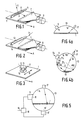
- Figure 1 shows a stimulable luminescent screen 1, formed from, for example, BaF(Cl,Br):Eu2+.
- Charge carriers (holes or electrons) released in the luminescent screen 1 by X-ray radiation occupy in the screen 1 energy levels which are available because of the presence of charge capturing centres.
- a laser beam 3 having a wavelength of, for example, 700nm
- the charge carriers are adjusted while supplying light having a wavelength of, for example, 450 nm to a lower energetic state.
- the released light is reflected towards a light guide 7 by means of a reflector 5 in the form of a parabolic mirror.
- the light guide 7 Via the light guide 7 the light arrives at a detector 9, for example, a photodiode or a photomultiplier tube, in which the incoming light flux is converted into an electric signal proportional thereto. Since the light guide is located in one of the focal points of the reflector 5, a shift of the reflector 5 relative to the light guide 7 results in a reduction of the light output at the detector 9.
- the screen 1 shifts relative to the reflector 5 and the light guide 7 in the direction indicated by the arrow A.
- the laser beam 3 is incident onto the screen in the second focal point of the mirror through an inlet aperture of the mirror 5. Varying the position of the laser beam 3 relative to the mirror 5 results in a fluctuating light output at the detector.
- Figure 2 shows an embodiment of a device for reading the luminescent screen 1 in accordance with the invention.
- the mirror 5 of Figure 1 is replaced by a reflection member 13 having a diffuse reflecting reflection plane 14.
- the light generated by the laser beam 3 in the screen 1 is reflected to all sides by the reflection plane 14, so that the reflection plane gives the impression of "lighting up”.
- the light reflected by the reflection body 13 is incident on the detector 9 via the light guide 7.
- a constant light flux to the detector 9 is possible without the necessity of imposing strict requirements on the shape of the reflection member 13 and the accurate relative positioning of the X-ray beam 3, the reflection body 13 and the light guide 7.
- the reflection member 13 extends, for example, over the entire width of the screen 1. A gap has been left open between the light guide 7 and the reflection member through which the lase beam 3 can impinge on the screen 1.
- Figure 3 shows an embodiment in which the reflection member 13 has an outlet aperture 15 cooperating with the detector 9.
- the laser beam 3 impinges on the screen 1 through an inlet aperture in the reflection member 13.
- the light released in that portion of the screen that is covered by the reflection member 13 impinges after a number of reflections between the reflection plane 14 and the screen 1 on the detector 9 through the outlet aperture.
- a laser 17, the detector 9 and the reflection member 13 can be moved as one integral unit relative to the screen in a direction indicated by the arrows A and B.
- Figure 4a shows the reflection member 13 in an embodiment in which the entire screen 1 is hemispherically covered by the reflection member 13.
- the exact shape of the reflection plane 14 is not important. After a number of diffuse reflections between the screen 1 and the reflection plane 14, the light generated by the laser 17 reaches the detector 9 through the outlet aperture 15. In this embodiment a relative movement of the screen 1 with respect to the reflection member 13, the laser 17 and the detector 9 is not required anymore.
- Figure 4b is a schematic representation of the diffuse reflection principle within a spherical reflector.
- the light generated by the laser 17 in an element 18 of the luminescent screen impinges from the diffuse reflecting reflection plane 14 of the reflection member 13 on a surface dA1.
- This small surface acts as a Lambert radiator and emits to a small surface dA2 of the reflection member a flux:
- L is the luminance (per solid angle)
- S the spacing between dA1 and dA2
- ⁇ the angle between the normal vector of dA1 and dA2 and S.
- R is the radius of the spherical reflection plane 14.
- Formula (3) shows that from the flux emitted from a first surface, a fraction lands on a second surface, which fraction is dual to the portion occupied by the second surface in proportion to the total reflection plane.
- the total outgoing flux from a surface of the reflection members is homogeneously distributed over the overall spherical surface 14. All the reflections within the sphere can be grouped into six fluxes: the flux from and to the surface of the reflection member A r , the flux from and to the surface of the detector A d and the flux from and to the surface of the laser A1.
- Pi1, Pi r and Pi d are the incident flux on the laser, the reflection member and the detector, respectively.
- Pt is the total outgoing flux
- Pt Pu1 + Pu r + Pu d .
- Pu1, Pu r and Pu d are the outgoing flux of the laser, the reflection member and the detector.
- a read rate By supplying a power flux P1 of 60mW, using, for example, a laser or a light source in the form of a television display tube, a read rate can be obtained which is equal to the read rate obtained when a known fibre optic light guide and reflecting reflection members are used, the efficiency being 20% at an applied flux of 30mW.
- FIG 5 shows an embodiment in which the reflection member 13 surrounds the luminescent screen.
- the reflection member is provided with two outlet apertures 15 and 15' cooperating with the detectors 9 and 9'.
- a summation unit 18 takes the sum of the signals from the detectors 15 and 15' and supplies it as one signal value from an output 19.
- the efficiency of the reflection member for light leaving the luminescent screen at the rear side is increased.
Landscapes
- Physics & Mathematics (AREA)
- Health & Medical Sciences (AREA)
- Life Sciences & Earth Sciences (AREA)
- General Physics & Mathematics (AREA)
- High Energy & Nuclear Physics (AREA)
- Molecular Biology (AREA)
- Spectroscopy & Molecular Physics (AREA)
- Radiography Using Non-Light Waves (AREA)
- Photometry And Measurement Of Optical Pulse Characteristics (AREA)
- Measurement Of Radiation (AREA)
Applications Claiming Priority (2)
| Application Number | Priority Date | Filing Date | Title |
|---|---|---|---|
| NL9000850 | 1990-04-11 | ||
| NL9000850A NL9000850A (nl) | 1990-04-11 | 1990-04-11 | Inrichting voor uitlezing van een stimuleerbaar luminescentiescherm. |
Publications (1)
| Publication Number | Publication Date |
|---|---|
| EP0451913A1 true EP0451913A1 (de) | 1991-10-16 |
Family
ID=19856907
Family Applications (1)
| Application Number | Title | Priority Date | Filing Date |
|---|---|---|---|
| EP91200807A Withdrawn EP0451913A1 (de) | 1990-04-11 | 1991-04-08 | Anordnung zum Auslesen eines anregbaren Leuchtschirms |
Country Status (3)
| Country | Link |
|---|---|
| EP (1) | EP0451913A1 (de) |
| JP (1) | JPH04225343A (de) |
| NL (1) | NL9000850A (de) |
Cited By (3)
| Publication number | Priority date | Publication date | Assignee | Title |
|---|---|---|---|---|
| EP0657749A1 (de) * | 1993-12-10 | 1995-06-14 | Agfa-Gevaert N.V. | Vorrichtung zum Auslesen von Strahlungsbildern durch Photostimulierung |
| EP0785445A1 (de) * | 1996-01-16 | 1997-07-23 | Agfa-Gevaert N.V. | Vorrichtung zum Auslesen eines Strahlungsbildes |
| EP1150137A2 (de) * | 2000-04-26 | 2001-10-31 | Fuji Photo Film Co., Ltd. | Bildlesegerät |
Citations (4)
| Publication number | Priority date | Publication date | Assignee | Title |
|---|---|---|---|---|
| EP0142833A2 (de) * | 1983-11-19 | 1985-05-29 | Fuji Photo Film Co., Ltd. | Strahlungsbild-Auslesevorrichtung |
| EP0169966A1 (de) * | 1984-03-09 | 1986-02-05 | Fuji Photo Film Co., Ltd. | Vorrichtung zum Auslesen von Strahlungsbildern |
| US4736102A (en) * | 1985-07-29 | 1988-04-05 | Minnesota Mining And Manufacturing Company | Reading device for stimulable phosphor panel |
| EP0265007A1 (de) * | 1986-10-13 | 1988-04-27 | Koninklijke Philips Electronics N.V. | Verfahren zum Herstellen eines Streureflektors |
-
1990
- 1990-04-11 NL NL9000850A patent/NL9000850A/nl not_active Application Discontinuation
-
1991
- 1991-04-08 JP JP7540891A patent/JPH04225343A/ja active Pending
- 1991-04-08 EP EP91200807A patent/EP0451913A1/de not_active Withdrawn
Patent Citations (4)
| Publication number | Priority date | Publication date | Assignee | Title |
|---|---|---|---|---|
| EP0142833A2 (de) * | 1983-11-19 | 1985-05-29 | Fuji Photo Film Co., Ltd. | Strahlungsbild-Auslesevorrichtung |
| EP0169966A1 (de) * | 1984-03-09 | 1986-02-05 | Fuji Photo Film Co., Ltd. | Vorrichtung zum Auslesen von Strahlungsbildern |
| US4736102A (en) * | 1985-07-29 | 1988-04-05 | Minnesota Mining And Manufacturing Company | Reading device for stimulable phosphor panel |
| EP0265007A1 (de) * | 1986-10-13 | 1988-04-27 | Koninklijke Philips Electronics N.V. | Verfahren zum Herstellen eines Streureflektors |
Non-Patent Citations (1)
| Title |
|---|
| PATENT ABSTRACTS OF JAPAN, vol. 9, no. 97 (P-352)[1820], 26th April 1985; & JP-A-59 223 402 (FUJITSU K.K.) 15-12-1984 * |
Cited By (4)
| Publication number | Priority date | Publication date | Assignee | Title |
|---|---|---|---|---|
| EP0657749A1 (de) * | 1993-12-10 | 1995-06-14 | Agfa-Gevaert N.V. | Vorrichtung zum Auslesen von Strahlungsbildern durch Photostimulierung |
| EP0785445A1 (de) * | 1996-01-16 | 1997-07-23 | Agfa-Gevaert N.V. | Vorrichtung zum Auslesen eines Strahlungsbildes |
| US5814831A (en) * | 1996-01-16 | 1998-09-29 | Agfa-Gevaert | Radiation read out apparatus |
| EP1150137A2 (de) * | 2000-04-26 | 2001-10-31 | Fuji Photo Film Co., Ltd. | Bildlesegerät |
Also Published As
| Publication number | Publication date |
|---|---|
| JPH04225343A (ja) | 1992-08-14 |
| NL9000850A (nl) | 1991-11-01 |
Similar Documents
| Publication | Publication Date | Title |
|---|---|---|
| EP0328538B1 (de) | Elliptischer zylinder-lichtabnehmer für ein photostimulierbares phosphor-bilderfassungsgerät | |
| CA1262190A (en) | Image read-out apparatus | |
| KR940004777B1 (ko) | 자극성 인광체 패널 판독장치 | |
| US4743758A (en) | Light collector for photo-stimulable phosphor imaging apparatus | |
| EP0516781B1 (de) | Streulichtminimierung bei einem zweiteiligen, v-förmigen spiegelkollektor | |
| US4564760A (en) | Radiation image read-out apparatus | |
| CN116018530A (zh) | X射线检测结构和系统 | |
| JP3357104B2 (ja) | 輝度制御を含むx線撮像システム | |
| EP0451913A1 (de) | Anordnung zum Auslesen eines anregbaren Leuchtschirms | |
| JP3187833B2 (ja) | 改善された集光効率を有する分割vルーフミラー型のコレクタ | |
| EP0358705B1 (de) | Durchsichtige lichtabnehmplatte zum aufnehmen von bildern aus photostimulierbarem phosphor | |
| US5140160A (en) | Collector for storage phosphor imaging system | |
| JPH03137599A (ja) | 放射性蛍光スクリーン | |
| JPH05345041A (ja) | 高エネルギー放射線検出装置 | |
| SU625639A3 (ru) | Сканирующее устройство дл передачи факсимиле через волоконную оптику | |
| JP3101223B2 (ja) | 放射読出し装置 | |
| US5134290A (en) | Collector for storage phosphor imaging system | |
| US4935945A (en) | System for exposing X-ray film to X-rays, to adequate density | |
| EP1007990B1 (de) | Optische abtastvorrichtung mit einem lesekopf | |
| JPH085745A (ja) | 放射線カメラ | |
| US4801188A (en) | Light guide optics | |
| EP1221631A1 (de) | Hoch effiziente Lichtleitervorrichtung | |
| EP1447682A1 (de) | Verwendung vom einem Prisma in einem system für digitale Radiographie zur Verbesserung der Effizienz | |
| JPS63236464A (ja) | 放射線画像情報読取装置 | |
| Carter et al. | X ray sensitive area detection device |
Legal Events
| Date | Code | Title | Description |
|---|---|---|---|
| PUAI | Public reference made under article 153(3) epc to a published international application that has entered the european phase |
Free format text: ORIGINAL CODE: 0009012 |
|
| AK | Designated contracting states |
Kind code of ref document: A1 Designated state(s): DE FR GB NL |
|
| 17P | Request for examination filed |
Effective date: 19920415 |
|
| STAA | Information on the status of an ep patent application or granted ep patent |
Free format text: STATUS: THE APPLICATION IS DEEMED TO BE WITHDRAWN |
|
| 18D | Application deemed to be withdrawn |
Effective date: 19931103 |