EP0451975B1 - C-, T- und S-Schalter, mechanisch betätigt von einem rotierenden Stellglied - Google Patents
C-, T- und S-Schalter, mechanisch betätigt von einem rotierenden Stellglied Download PDFInfo
- Publication number
- EP0451975B1 EP0451975B1 EP91302472A EP91302472A EP0451975B1 EP 0451975 B1 EP0451975 B1 EP 0451975B1 EP 91302472 A EP91302472 A EP 91302472A EP 91302472 A EP91302472 A EP 91302472A EP 0451975 B1 EP0451975 B1 EP 0451975B1
- Authority
- EP
- European Patent Office
- Prior art keywords
- pin
- switch
- pins
- connector
- cam
- Prior art date
- Legal status (The legal status is an assumption and is not a legal conclusion. Google has not performed a legal analysis and makes no representation as to the accuracy of the status listed.)
- Expired - Lifetime
Links
Images




Classifications
-
- H—ELECTRICITY
- H01—ELECTRIC ELEMENTS
- H01P—WAVEGUIDES; RESONATORS, LINES, OR OTHER DEVICES OF THE WAVEGUIDE TYPE
- H01P1/00—Auxiliary devices
- H01P1/10—Auxiliary devices for switching or interrupting
- H01P1/12—Auxiliary devices for switching or interrupting by mechanical chopper
- H01P1/125—Coaxial switches
-
- H—ELECTRICITY
- H01—ELECTRIC ELEMENTS
- H01H—ELECTRIC SWITCHES; RELAYS; SELECTORS; EMERGENCY PROTECTIVE DEVICES
- H01H51/00—Electromagnetic relays
- H01H51/22—Polarised relays
- H01H51/2263—Polarised relays comprising rotatable armature, rotating around central axis perpendicular to the main plane of the armature
Definitions
- This invention relates to a microwave switch and, in particular, to a mechanically-operated transfer switch that is an S-switch, a C-switch, a T-switch or the like.
- Transfer switches such as C-switches, S-switches or T-switches are known and are widely used in the space communications industry.
- a communications satellite will contain numerous coaxial C-switches, S-switches or T-switches.
- previous switches have a much larger mass and a much larger volume than switches of the present invention. Further, previous switches are more complex and expensive to manufacture and some previous switches have a relatively large number of moving parts making them more susceptible to failure.
- the switch of the present application is an improvement over the switch described in US-A-4,851,801, entitled “Microwave C-switches and S-switches", naming Klaus G. Engel as inventor and being issued on July 25th, 1989.
- the present invention is directed to a microwave switch of the general type disclosed in EP-A-0163497, having an RF cavity housing, an actuator and power means for repositioning said actuator arranged as follows:-
- Mass and volume are always critical parameters for space applications. Any savings in mass and volume are readily converted to cost savings, or higher communications capacity, or longer life for the satellite or a combination of these factors. Similarly, the reliability of space craft components is crucial to the success of the satellite as there are no means for correcting any malfunctions once the satellite is launched. When a component used in a satellite can be manufactured in a much simpler manner than previously, that can be very important as such a component is usually less susceptible to failure.
- the switch according to the present invention is characterised in that the actuator is a rotary cam mounted outside said housing and connected to said power means so that said power means can rotate said cam to at least two predetermined positions.
- the cam has at least one ridge and at least one indentation located thereon.
- the at least one ridge and the at least one indentation are located so that when a ridge overrides a pin, said pin is depressed and when an indentation overrides a pin, said pin is released.
- the ridge and the indentation override said pins as said cam rotates.
- the at least one ridge and the at least one indentation are co-ordinated with the power means so that appropriate conductor paths are connected and interrupted substantially at the same time.
- the cam, the power means, the springs, the pins and the connectors are the only movable components of the switch.
- FIGs 1a and 1b there is shown a side view of a prior art coaxial C-switch 10 having electromagnets 41, 42 mounted with a housing 11 (only part of which is shown).
- the switch is shown in a first position in Figure 1a where the supply of electrical current to the electromagnet 42 has caused a linear movement with a corresponding force to displace rocker arm 51 about its pivot point causing circular rod 63 to move in a linear direction and make contact with conductor 71.
- the supply of an electrical current to electromagnet 41 instead of the electromagnet 42 causes a further linear movement that displaces rocker arm 51 to a second position as shown in Figure 1b.
- the switch 10 can continuously be operated to return to the first position shown in Figure 1a from the second positon shown in Figure 1b, return spring 62 causing rod 61 to move reed 81 out of contact with conductors 71, 72.
- return spring 62 causing rod 61 to move reed 81 out of contact with conductors 71, 72.
- To achieve the operation of the switch 10 requires two assemblies as shown in Figures 1a and 1b with a duplication of parts.
- the S-switch would be larger in volume and mass than the C-switch.
- the opposing return spring which has a compressed force associated with the switch operation is usually some fraction of the actuator thrust. This can leave the switch vulnerable to contact sticking and hence degrade the reliability of the switch.
- FIGS 2a, 2b and 2c there is shown a prior art electromagnetic switch 15 with a mechanical lever actuated mechanism.
- the switch 15 has a dual polarity electromagnetic coil 111, 112 configuration, together with an RF cavity assembly 13 housed within a primary housing 14.
- an electrical current is applied to either winding 111 or 112. The application of such an electrical field will cause a magnetic field to attract the opposite field polarity of a magnetized clapper arm 121.
- the switch can be activated by applying a current to coil winding 111 that attracts a clapper assembly pole 132 causing clapper arm 121 to rotate in a clockwise direction as shown in Figure 2a until the pole 132 comes to rest at actuator assembly stop 113.
- Figure 2b it is shown that the corresponding rotational movement of rocker arm 52 will cause a linear movement of plunger 65 that causes reed 82 to connect with the connector contacts 73, 74, thereby connecting port 1 and port 2.
- the electrical coil 112 is energized by an electrical current, the clapper magnetic pole 131 will be attracted to the reversed polarity of the magnetic stop 113 that causes the clapper assembly to rotate counterclockwise.
- FIG 3 there is shown a sectional side view of a prior art electromagnetic switch 16 with the RF cavity housing 12 located within a housing 11.
- the switch 16 has conductor paths located in the RF cavity housing 12.
- Four movable connectors 25, 26, 27, 28 are shown which are fastened to four armatures 151, 152, 153, 154.
- the connectors 25, 26, 27, 28 are each long enough to comprise one entire conductor path for the switch 16.
- the upper and lower magnetic returns 133, 134 are separated by a centre plate 135 and upper and lower windings 116 and 117, respectively.
- centre plate 135 and upper and lower windings 116, 117 are fastened with a pin 132 that serves as a back iron to the magnetic circuit.
- the magnets are supported on the centre plate 135, one for each of the armatures 153, 152, 151, 154 respectively.
- the magnets are oriented as such that opposite armatures say 152, 154 experience the same magnetic polarity.
- the two magnets for the two remaining armatures 151, 153 respectively are oriented with an opposite or opposing magnetic field.
- the armatures 152, 154 oppose the armatures 151, 153.
- An electrical pulse supplied to either of the coil windings 116, 117 will cause one set of opposing armatures 152, 154 to rise, thus disconnecting the attached connector from the respective conductor path in which it is located and interrupting said path.
- the remaining part of armatures 151, 153 will simultaneously lower, thus causing a connection between their respective connectors and conductor paths.
- the coil windings can be configured to operate the switch to satisfy two principles.
- the winding direction of coils 116, 117 can be utilized electrically to function in a series or parallel circuit arrangement.
- the advantage of an independent coil with the alternative parallel circuit will permit redundance if one coil should fail or an additional margin of the applied voltage with reference to the switching threshold applied voltage.
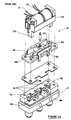
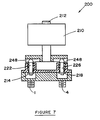
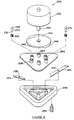
- a coaxial S-switch 200 embodying the invention has an RF cavity housing 204 including a cover 206, an actuator 208 having a circular shape and a power means or motor 210.
- the motor 210 is a permanent magnet stepper motor and is connected to the actuator 208 by a shaft 212.
- the actuator 208 is a rotary cam. It can be seen that the switch 200 has four conductor paths located in the RF cavity housing 204. Four movable connectors or reeds 214, 216, 218, 220 are connected to pins 222, 224, 226, 228, respectively.
- Each of the connectors 214, 216, 218, 220 contains a hole 230 therein for receiving one end 232 of each of the pins 222, 224, 226, 228, respectively.
- Each hole 230 is located approximately at a longitudinal centre of each of the connectors.
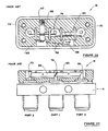
- the housing 204 contains four ports 1, 2, 3, 4 (only three of which are shown in Figure 5). The ports are arranged in a square configuration.
- the cover 206 can be affixed to the housing 204 by a threaded bolt 233.
- the cover 206 contains four cylindrically-shaped projections 234, each projection having an open top 236.
- the projections 234 are arranged relative to one another so that when the cover 206 is in place on the housing 204, one pin is located in each projection.
- the top 236 of each projection 234 provides a limit for the distance that the pin located in the projection can be depressed by a ridge of the cover.
- the cover 206 contains one opening to receive each of the pins 222, 224, 226, 228. While an end 232 of each pin is attached to a connector, a free end 238 of each pin is located outside of said housing 204, including said cover 206.
- a spring 240 is located in each projection 234 between a head 242 of each pin and an outer surface 244 of the housing. The projection 234 provides retention means for the spring 240. In a released position, the free end of each pin protrudes from said housing beyond said top. Each spring 240 is compressed between said head and said outer surface and tends to force the free end 238 away from said housing 204 including said cover 206.
- the actuator 208 is a rotary cam that is mounted outside of said housing and connector to the motor 210 by means of the shaft 212.
- the cam 208 has two ridges 246 (only one of which is shown in Figure 5) and two indentations 248 located thereon so that when the ridges 246 override a pin, the pin is depressed and when an indentation 248 overrides a pin, the pin is released.
- the size of the cam 208 and the location of the ridges 246 and indentations 248 thereon is determined by the location of the pins protruding from the projections 234 of the cover 236.
- the ridges and indentations are co-ordinated with the motor so that as the cam is rotated, appropriate conductor paths of the switch are connected and interrupted substantially at the same time.
- the cam, the power means, the springs and the connectors are the only movable components of the switch 200.
- Each pin has two distinct positions, a depressed position and a released position.
- the conductor path, in which that pin and connector are located is connected. Further, when a pin is in a released position, the conductor path, in which that pin is located, is interrupted.
- the switch 200 is shown in various positions.
- the pins 222, 226 are both in a depressed position with the ridges 246 forcing the pins downward against the springs 240 and connecting the conductor paths in which the connectors 214, 218 are located.
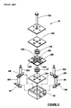
- a T-switch 250 having a motor 252, an actuator 254, a cover 256 and a housing 258, said housing including said cover 256.
- the motor 252 has a shaft 260.
- the housing 258 has six conductor paths, three along the periphery of said housing and three radially extending from a centre of said housing.
- the switch 250 has four ports 262, only one of which is shown in Figure 8.
- the short connectors 264 are designed to be placed in the radial connecting paths.
- the long connectors 268 are designed to be located in the conductor paths along a periphery of the housing 258.
- the cover 256 has a plurality of cylindrically-shaped projections 234 thereon, said projections being open at a top 236.
- Each of the projections 234 contains a pin 270 which is spring-mounted via a spring 240 so that a lower end 232 is located within the hole 230 while a free end 238 extends beyond the top 236 when the ends are in a released position.
- the cam 256 has two ridges located thereon, together with large indentations between said ridges.
- the switch 250 has three distinct positions. When the cam is in a first position, the two ridges 246 will depress a first long connector 268 and a first short connector 264, while the remaining connectors will be in a released position. The connection will therefore be completed in the conductor paths in which the connectors are depressed and interrupted in those conductor paths in which the connectors are released.
- a second long connector 268 In a second position, a second long connector 268 will be depressed and a second short connector normal thereto will also be depressed, the remaining connectors being released. Similarly, in a third position, a third long connector 268 will be depressed and a third short connector normal thereto will be depressed, with the remaining connectors being released.
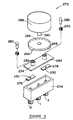
- FIG. 9 there is shown a C-switch 272 with an RF cavity housing 274 having three ports 1, 2, 3 by springs 240.
- Projections 234 on the housing cover 284 have open tops 236.
- a cam 286 has one ridge 246 and one indentation 248 thereon.
- the indentation 248 is over the other pin 282 and connecting the conductor path in which the connector 278 is located.
- the indentation 248 is above the pin 280 and the conductor path between the ports 1 and 2 is interrupted as the connector 276 and the pin 280 are in a released position.
- Switches of the present invention can be designed so that a particular conductor path is connected simultaneously with another conductor path being interrupted.
- the switching time is the time between the interruption of one set of conductor paths in a switch and the connection of another set of conductor paths.
- a switch can be designed so that the connection/interruption sequence can be altered to best suit the needs of specific circumstances. For example, by increasing the rotational length of the ridges of the cam, the conductor paths of the switch that are being connected are connected slightly before the conductor paths that are being interrupted are in fact interrupted. Since the switches of the present invention have a minimum of moving parts, the switch can be manufactured efficiently and less expensively than previously switches. Also, the switch has a high reliability as the connectors, which include the pins, the springs and the actuator are the only moving parts.
- the switch can be made small enough to have a cross-sectional area normal to the axis of movement of the pins of substantially 0.95 square inches (6.13 square cms.). Since the pins, actuator and connectors can be made of lightweight materials, the motor can be made smaller and large mass savings can be achieved.
- the connectors can be made of various materials that will be suitable, including without limitation, a conducting plastic material.
Landscapes
- Physics & Mathematics (AREA)
- Electromagnetism (AREA)
- Waveguide Switches, Polarizers, And Phase Shifters (AREA)
- Coupling Device And Connection With Printed Circuit (AREA)
- Details Of Connecting Devices For Male And Female Coupling (AREA)
Claims (14)
- Mikrowellenschalter, umfassend ein HF-Hohlleitergehäuse (204), ein Stellglied (208) und ein Antriebsmittel (210) zum Umstellen des Stellglieds, folgendermaßen angeordnet, daß:(a) das Gehäuse mindestens zwei Leiterwege aufweist, die mindestens drei Anschlüsse (1, 2, 3) miteinander verbinden, das Gehäuse weiter mindestens zwei Stifte (222, 224) enthält, jeder Stift einen separaten Verbinder trägt, ein Verbinder in jedem Leiterweg liegt, jeder Verbinder zwei linear gegeneinander versetzte Stellungen einnehmen kann;(b) jeder Verbinder den Leiterweg in einer Stellung schließt und den Leiterweg in einer anderen Stellung unterbricht;(c) das Gehäuse eine Öffnung (236) für jeden Stift aufweist, jede Öffnung groß genug ist, um einen Stift (222, 224) darin gefedert befestigen zu können, jeder Stift mit Federn (240) federgelagert ist und ein Ende aufweist, das mit dem Verbinder verbunden ist, der unmittelbar neben dieser Öffnung liegt, der Stift ein anderes, freies Ende aufweist, das freie Ende außerhalb des Gehäuses liegt, wenn der Stift entlastet ist, die Federlagerung dazu neigt, das freie Ende des Stiftes vom Gehäuse wegzudrücken, jeder Stift zwei Stellungen einnehmen kann, und zwar eine niedergedrückte Stellung und eine entlastete Stellung; wobei der Schalter dadurch gekennzeichnet ist, daß das Stellglied eine Nockenscheibe (208) ist, die außerhalb des Gehäuses befestigt ist und mit dem Antriebsmittel so verbunden ist, daß das Antriebsmittel die Nockenscheibe in mindestens zwei vorbestimmte Stellungen drehen kann, daß die Nockenscheibe mindestens einen Kamm (246) und mindestens eine Vertiefung aufweist, daß dieser mindestens eine Kamm und diese mindestens eine Vertiefung (248) so gelegen sind, daß, wenn ein Kamm über einen Stift hinwegfährt, der Stift niedergedrückt wird, und wenn eine Vertiefung über einen Stift, hinwegfährt der Stift entlastet wird, daß der Kamm und die Vertiefung über die Stifte hinwegfahren, wenn sich die Nockenscheibe dreht;daß der mindestens eine Kamm und die mindestens eine Vertiefung so mit dem Antriebsmittel abgestimmt sind, daß geeignete Leiterwege im wesentlichen gleichzeitig verbunden und unterbrochen werden und daß die Nockenscheibe, das Antriebsmittel, die Federn, die Stifte und die Verbinder die einzigen beweglichen Teile des Schalters sind.
- Mikrowellenschalter nach Anspruch 1, wobei ein Leiterweg durch einen Verbinder geschlossen wird, wenn der Verbinder in einer niedergedrückten Stellung ist, und unterbrochen wird, wenn der Verbinder in einer entlasteten Stellung ist.
- Mikrowellenschalter nach Anspruch 2, wobei die Kämme und Vertiefungen auf der Nockenscheibe so relativ zueinander angeordnet sind, daß entsprechende Leiterwege gleichzeitig geschlossen und unterbrochen werden.
- Mikrowellenschalter nach Anspruch 2, wobei die Kämme und Vertiefungen so relativ zueinander angeordnet sind, daß die Leiterwege, die gerade geschlossen werden, geschlossen werden kurz bevor die Leiterwege, die gerade unterbrochen werden, tatsächlich unterbrochen werden.
- Mikrowellenschalter nach Anspruch 2, wobei die Nockenscheibe eine kreisrunde Form aufweist und das Antriebsmittel ein Motor ist.
- Mikrowellenschalter nach Anspruch 2, wobei das freie Ende jedes Stiftes einen abgerundeten Kopf (238) aufweist und jeder Stift federgelagert ist mit einer Feder, die zwischen diesem Kopf und einer Außenfläche des Gehäuses zusammengedrückt wird.
- Mikrowellenschalter nach Anspruch 6, wobei jede Öffnung in dem Gehäuse von einem zylinderförmigen Fortsatz (234) mit offener Oberseite umgeben ist, diese Oberseite eine Grenze für die Strecke bildet, entlang der der Stift von einem Kamm der Nockenscheibe niedergedrückt werden kann, und auch als Befestigung für die Feder dient, und das freie Ende des Stiftes in einer entlasteten Stellung aus dem Gehäuse über diese Oberseite hinausragt.
- Mikrowellenschalter nach Anspruch 2, 3 oder 4, wobei der Schalter ein S-Schalter (200) ist und das Gehäuse vier Leiterwege, vier Anschlüsse, vier Stifte (222, 224, 226, 228), vier Öffnungen, vier zylindrische Fortsätze und vier Verbinder (214, 216, 218, 220) enthält, die Verbinder und Stifte in einer gewöhnlich quadratischen Konfiguration angeordnet sind, wobei jeder Stift mit einem separaten Verbinder verbunden ist, die Nockenscheibe abwechselnd zwei Kämme und zwei Vertiefungen angeordnet enthält, in der gleichen gewöhnlich quadratischen Anordnung wie die Stifte, die Nockenscheibe zwei unterschiedliche Stellungen einnehmen kann, in einer ersten Stellung ein erster und dritter Stift (222, 226) niedergedrückt und ein zweiter und vierter Stift (224,228) entlastet werden, und in einer zweiten Stellung ein zweiter und vierter Stift niedergedrückt und ein erster und dritter Stift entlastet werden.
- Mikrowellenschalter nach Anspruch 2, 3 oder 4, wobei der Schalter ein T-Schalter (250) ist und das Gehäuse sechs Leiterwege, vier Anschlüsse (262), sechs Stifte (270) und sechs Verbinder (264, 268) enthält; jeder Stift mit einem separaten Verbinder verbunden ist; ein Verbinder Anschluß eins und zwei verbindet, ein Verbinder Anschluß zwei und drei verbindet, ein Verbinder Anschluß eins und drei verbindet, ein Verbinder Anschluß eins und vier verbindet, ein Verbinder Anschluß zwei und vier verbindet und ein Verbinder Anschluß drei und vier verbindet; die Nockenscheibe (254) zwei Kämme und vier Vertiefungen aufweist, die Kämme und Vertiefungen so angeordnet sind, daß sie mit der Lage der Stifte so übereinstimmen, daß die Nockenscheibe mindestens drei verschiedene Stellungen einnehmen kann; und in jeder Stellung zwei Stifte niedergedrückt sind und die verbleibenden Stifte entlastet sind.
- Mikrowellenschalter nach Anspruch 2, 3 oder 4, wobei der Schalter ein T-Schalter ist und das Gehäuse sechs Leiterwege, vier Anschlüsse, sechs Stifte und sechs Verbinder enthält; jeder Stift mit einem Verbinder verbunden ist; ein Verbinder Anschluß eins und zwei verbindet, ein Verbinder Anschluß zwei und drei verbindet, ein Verbinder Anschluß eins und drei verbindet, ein Verbinder Anschluß eins und vier verbindet, ein Verbinder Anschluß zwei und vier verbindet und ein Verbinder Anschluß drei und vier verbindet; die Nockenscheibe zwei Kämme und vier Vertiefungen aufweist; die Kämme und Vertiefungen so angeordnet sind, daß sie mit der Lage der Stifte übereinstimmen; die Nockenscheibe drei Stellungen einnehmen kann, eine erste Stellung, wo Stifte eins und vier niedergedrückt und alle übrigen Stifte entlastet sind, eine zweite Stellung, wo Stifte zwei und fünf niedergedrückt sind und alle übrigen Stifte entlastet sind, und eine dritte Stellung, wo Stifte drei und sechs niedergedrückt und die übrigen Stifte entlastet sind.
- Mikrowellenschalter nach Anspruch 2, 3 oder 4, wobei der Schalter aus der Gruppe eines C-Schalters oder eines T-Schalters ausgewählt ist und eine normal zu einer Bewegungsachse der Reed-Magnetstifte verlaufende Querschnittsfläche von im wesentlichen 0,95 Quadratzoll (6,13 cm) aufweist.
- Mikrowellenschalter nach Anspruch 2, 3 oder 4, wobei der Schalter ein C-Schalter (272) ist und das Gehäuse zwei Leiterwege, drei Anschlüsse (1, 2, 3), zwei Stifte (280, 282) und zwei Verbinder (276, 278) enthält; jeder Stift mit einem separaten Verbinder verbunden ist; ein Verbinder Anschluß eins und zwei verbindet und der andere Verbinder Anschluß zwei und drei verbindet; die Nockenscheibe (286) einen Kamm und eine Vertiefung aufweist, die so angeordnet sind, daß sie mit der Lage der Stifte übereinstimmen; die Nockenscheibe zwei verschiedene Stellungen einnehmen kann, in einer ersten Stellung ein erster Stift (280) niedergedrückt und ein zweiter Stift (282) entlastet wird und in einer zweiten Stellung der zweite Stift niedergedrückt und der erste Stift entlastet wird.
- Mikrowellenschalter nach Anspruch 2, 3 oder 4, wobei der Leiterweg verbunden ist, wenn der Stift niedergedrückt ist, und unterbrochen ist, wenn ein Stift entlastet ist.
- Mikrowellenschalter nach Anspruch 2, 3 oder 4, wobei jeder Stift ungefähr in der Mitte der Längsachse jedes Verbinders liegt.
Applications Claiming Priority (2)
| Application Number | Priority Date | Filing Date | Title |
|---|---|---|---|
| CA002014584A CA2014584C (en) | 1990-04-12 | 1990-04-12 | C-, t- and s-switches that are mechanically operated by a rotary actuator |
| CA2014584 | 1990-04-12 |
Publications (3)
| Publication Number | Publication Date |
|---|---|
| EP0451975A2 EP0451975A2 (de) | 1991-10-16 |
| EP0451975A3 EP0451975A3 (en) | 1992-02-05 |
| EP0451975B1 true EP0451975B1 (de) | 1996-02-28 |
Family
ID=4144749
Family Applications (1)
| Application Number | Title | Priority Date | Filing Date |
|---|---|---|---|
| EP91302472A Expired - Lifetime EP0451975B1 (de) | 1990-04-12 | 1991-03-21 | C-, T- und S-Schalter, mechanisch betätigt von einem rotierenden Stellglied |
Country Status (4)
| Country | Link |
|---|---|
| US (1) | US5063364A (de) |
| EP (1) | EP0451975B1 (de) |
| CA (1) | CA2014584C (de) |
| DE (1) | DE69117320T2 (de) |
Families Citing this family (17)
| Publication number | Priority date | Publication date | Assignee | Title |
|---|---|---|---|---|
| JP3078946B2 (ja) * | 1993-03-11 | 2000-08-21 | インターナショナル・ビジネス・マシーンズ・コーポレ−ション | 一括消去型不揮発性メモリの管理方法及び半導体ディスク装置 |
| US5329119A (en) * | 1993-04-23 | 1994-07-12 | Xerox Corporation | Rotary switch actuator for detecting the presence of a sheet or the like with a hub member having inclined surface segments |
| US5493478A (en) * | 1994-02-04 | 1996-02-20 | Motorola, Inc. | Cam actuated control device including a plurality of binary switches coplanarly mounted on a circuit substrate |
| US5936482A (en) * | 1997-11-20 | 1999-08-10 | Hughes Electronics Corporation | Three dimensional polyhedral-shaped microwave switches |
| US6043440A (en) * | 1998-09-11 | 2000-03-28 | Teledyne Industries, Inc. | Microwave switch contact interface |
| US5952902A (en) * | 1999-03-12 | 1999-09-14 | Kich; Rolf | Coaxial "M" switch |
| US6037849A (en) * | 1999-07-26 | 2000-03-14 | Delaware Capital Formation, Inc. | Microwave switch having magnetically retained actuator plate |
| KR100343496B1 (ko) * | 2000-07-29 | 2002-07-18 | 김덕용 | 고주파용 스위치 |
| US6856212B2 (en) * | 2002-12-16 | 2005-02-15 | Com Dev Ltd. | Incomplete mechanical contacts for microwave switches |
| US7135947B2 (en) | 2004-01-29 | 2006-11-14 | Com Dev Ltd. | Hybrid microwave T-switch actuator |
| JP4466505B2 (ja) * | 2005-08-12 | 2010-05-26 | オムロン株式会社 | リレー |
| US7843289B1 (en) * | 2005-08-19 | 2010-11-30 | Scientific Components Corporation | High reliability microwave mechanical switch |
| US20080283379A1 (en) * | 2007-05-18 | 2008-11-20 | Teledyne Technologies Incorporated | Coaxial switch with reduced tribo-electric charge accumulation |
| US7876185B2 (en) * | 2008-05-05 | 2011-01-25 | Teledyne Technologies Incorporated | Electromagnetic switch |
| DE102010017872B4 (de) * | 2010-04-21 | 2012-06-06 | Saia-Burgess Dresden Gmbh | Bistabiles Kleinrelais großer Leistung |
| US10249463B1 (en) * | 2016-03-04 | 2019-04-02 | Scientific Components Corporation | Magnetically operated electro-mechanical latching switch |
| RU209147U1 (ru) * | 2021-07-26 | 2022-02-03 | Акционерное общество "Научно-производственное предприятие "Алмаз" (АО "НПП "Алмаз") | Расположение контактных пластин коаксиального свч-переключателя |
Family Cites Families (9)
| Publication number | Priority date | Publication date | Assignee | Title |
|---|---|---|---|---|
| US2997669A (en) * | 1958-02-03 | 1961-08-22 | Thompson Ramo Wooldridge Inc | Broad band lobing switch |
| US3407278A (en) * | 1967-04-17 | 1968-10-22 | Essex Wire Corp | Oscillatory electric switch construction |
| GB1185942A (en) * | 1968-05-10 | 1970-03-25 | Electronic Components Ltd | Improvements in or relating to Rotary Electrical Switches |
| DE1938777A1 (de) * | 1969-07-30 | 1971-02-11 | Spinner Dr Ing Georg | Koaxialdrehschalter,insbesondere fuer HF-Schaltfelder |
| US3739306A (en) * | 1970-09-03 | 1973-06-12 | Bunker Ramo | Microwave coaxial switch |
| JPS6049361B2 (ja) * | 1978-06-05 | 1985-11-01 | 日本電気株式会社 | 同軸線路切換装置 |
| JPS60251701A (ja) * | 1984-05-28 | 1985-12-12 | Nec Corp | マイクロ波スイツチ |
| US4779066A (en) * | 1987-04-20 | 1988-10-18 | Sage Laboratories, Inc. | Multi-position switch |
| CA1283680C (en) * | 1988-09-28 | 1991-04-30 | Klaus Gunter Engel | Microwave c-switches and s-switches |
-
1990
- 1990-04-12 CA CA002014584A patent/CA2014584C/en not_active Expired - Lifetime
- 1990-05-02 US US07/517,686 patent/US5063364A/en not_active Expired - Lifetime
-
1991
- 1991-03-21 EP EP91302472A patent/EP0451975B1/de not_active Expired - Lifetime
- 1991-03-21 DE DE69117320T patent/DE69117320T2/de not_active Expired - Fee Related
Also Published As
| Publication number | Publication date |
|---|---|
| CA2014584C (en) | 1992-06-09 |
| EP0451975A3 (en) | 1992-02-05 |
| CA2014584A1 (en) | 1992-06-09 |
| US5063364A (en) | 1991-11-05 |
| DE69117320D1 (de) | 1996-04-04 |
| DE69117320T2 (de) | 1996-08-29 |
| EP0451975A2 (de) | 1991-10-16 |
Similar Documents
| Publication | Publication Date | Title |
|---|---|---|
| US5063364A (en) | C-, t- and s-switches that are mechanically operated by a rotary actuator | |
| EP0451974B1 (de) | C-, S- und T-Schalter, betätigt von Permanentmagneten | |
| US5281936A (en) | Microwave switch | |
| US6337612B1 (en) | Switch using solenoid | |
| US4453148A (en) | Key switch | |
| US6650210B1 (en) | Electromechanical switch device | |
| EP0764338B1 (de) | Mikrowellen multiport-übertragungsschalter | |
| US5652558A (en) | Double pole double throw RF switch | |
| US4965542A (en) | Magnetic switch for coaxial transmission lines | |
| EP0186393B1 (de) | Fernsteuerbares Relais | |
| US4851801A (en) | Microwave C-switches and S-switches | |
| CA1152132A (en) | Electromagnetic relay | |
| US6133812A (en) | Switching relay with magnetically resettable actuator mechanism | |
| GB2227608A (en) | Solenoid actuators | |
| US3835425A (en) | Electromagnetic relay with reversible switch modules | |
| KR20050029042A (ko) | 고주파 동축 스위치 | |
| US3458839A (en) | Locking reed and ball switches and matrices | |
| JP4158876B2 (ja) | 電力用開閉装置の操作装置 | |
| US3537047A (en) | Electric snap switch | |
| JP4515664B2 (ja) | 電力用開閉装置の操作装置 | |
| US6356174B1 (en) | Operator for an electromagnetic switching device | |
| US2553478A (en) | Rotary electromagnetic transfer switch | |
| JPH0428134A (ja) | リモコンリレー | |
| US4521757A (en) | High speed electromagnetic mechanical switch | |
| US3040145A (en) | Electromagnetic switch |
Legal Events
| Date | Code | Title | Description |
|---|---|---|---|
| PUAI | Public reference made under article 153(3) epc to a published international application that has entered the european phase |
Free format text: ORIGINAL CODE: 0009012 |
|
| AK | Designated contracting states |
Kind code of ref document: A2 Designated state(s): DE FR GB IT SE |
|
| PUAL | Search report despatched |
Free format text: ORIGINAL CODE: 0009013 |
|
| AK | Designated contracting states |
Kind code of ref document: A3 Designated state(s): DE FR GB IT SE |
|
| RHK1 | Main classification (correction) |
Ipc: H01P 1/10 |
|
| 17P | Request for examination filed |
Effective date: 19920804 |
|
| 17Q | First examination report despatched |
Effective date: 19940613 |
|
| GRAA | (expected) grant |
Free format text: ORIGINAL CODE: 0009210 |
|
| AK | Designated contracting states |
Kind code of ref document: B1 Designated state(s): DE FR GB IT SE |
|
| ITF | It: translation for a ep patent filed | ||
| REF | Corresponds to: |
Ref document number: 69117320 Country of ref document: DE Date of ref document: 19960404 |
|
| PG25 | Lapsed in a contracting state [announced via postgrant information from national office to epo] |
Ref country code: SE Effective date: 19960531 |
|
| ET | Fr: translation filed | ||
| PLBE | No opposition filed within time limit |
Free format text: ORIGINAL CODE: 0009261 |
|
| STAA | Information on the status of an ep patent application or granted ep patent |
Free format text: STATUS: NO OPPOSITION FILED WITHIN TIME LIMIT |
|
| 26N | No opposition filed | ||
| REG | Reference to a national code |
Ref country code: GB Ref legal event code: IF02 |
|
| PGFP | Annual fee paid to national office [announced via postgrant information from national office to epo] |
Ref country code: GB Payment date: 20070328 Year of fee payment: 17 |
|
| PGFP | Annual fee paid to national office [announced via postgrant information from national office to epo] |
Ref country code: DE Payment date: 20070523 Year of fee payment: 17 |
|
| PGFP | Annual fee paid to national office [announced via postgrant information from national office to epo] |
Ref country code: IT Payment date: 20070726 Year of fee payment: 17 |
|
| PGFP | Annual fee paid to national office [announced via postgrant information from national office to epo] |
Ref country code: FR Payment date: 20070323 Year of fee payment: 17 |
|
| GBPC | Gb: european patent ceased through non-payment of renewal fee |
Effective date: 20080321 |
|
| REG | Reference to a national code |
Ref country code: FR Ref legal event code: ST Effective date: 20081125 |
|
| PG25 | Lapsed in a contracting state [announced via postgrant information from national office to epo] |
Ref country code: DE Free format text: LAPSE BECAUSE OF NON-PAYMENT OF DUE FEES Effective date: 20081001 |
|
| PG25 | Lapsed in a contracting state [announced via postgrant information from national office to epo] |
Ref country code: FR Free format text: LAPSE BECAUSE OF NON-PAYMENT OF DUE FEES Effective date: 20080331 |
|
| PG25 | Lapsed in a contracting state [announced via postgrant information from national office to epo] |
Ref country code: GB Free format text: LAPSE BECAUSE OF NON-PAYMENT OF DUE FEES Effective date: 20080321 |
|
| PG25 | Lapsed in a contracting state [announced via postgrant information from national office to epo] |
Ref country code: IT Free format text: LAPSE BECAUSE OF NON-PAYMENT OF DUE FEES Effective date: 20080321 |