EP0451995B1 - Procédé et appareil pour la formation d'images en demi-teintes - Google Patents
Procédé et appareil pour la formation d'images en demi-teintes Download PDFInfo
- Publication number
- EP0451995B1 EP0451995B1 EP91302720A EP91302720A EP0451995B1 EP 0451995 B1 EP0451995 B1 EP 0451995B1 EP 91302720 A EP91302720 A EP 91302720A EP 91302720 A EP91302720 A EP 91302720A EP 0451995 B1 EP0451995 B1 EP 0451995B1
- Authority
- EP
- European Patent Office
- Prior art keywords
- map
- tone dot
- control signal
- tone
- scanning
- Prior art date
- Legal status (The legal status is an assumption and is not a legal conclusion. Google has not performed a legal analysis and makes no representation as to the accuracy of the status listed.)
- Expired - Lifetime
Links
- 238000000034 method Methods 0.000 title claims description 15
- 238000003384 imaging method Methods 0.000 title description 2
- 238000000926 separation method Methods 0.000 claims description 5
- 230000005855 radiation Effects 0.000 claims description 4
- 238000010276 construction Methods 0.000 description 1
- 238000007796 conventional method Methods 0.000 description 1
- 238000010586 diagram Methods 0.000 description 1
- 230000000737 periodic effect Effects 0.000 description 1
Images

Classifications
-
- H—ELECTRICITY
- H04—ELECTRIC COMMUNICATION TECHNIQUE
- H04N—PICTORIAL COMMUNICATION, e.g. TELEVISION
- H04N1/00—Scanning, transmission or reproduction of documents or the like, e.g. facsimile transmission; Details thereof
- H04N1/40—Picture signal circuits
- H04N1/405—Halftoning, i.e. converting the picture signal of a continuous-tone original into a corresponding signal showing only two levels
- H04N1/4055—Halftoning, i.e. converting the picture signal of a continuous-tone original into a corresponding signal showing only two levels producing a clustered dots or a size modulated halftone pattern
- H04N1/4058—Halftoning, i.e. converting the picture signal of a continuous-tone original into a corresponding signal showing only two levels producing a clustered dots or a size modulated halftone pattern with details for producing a halftone screen at an oblique angle
Definitions
- the invention is concerned with the reproduction of an image in half-tone form by modulating a scanning beam in a binary manner to cause the selective exposure of portions of half-tone dots corresponding to image pixels.
- the invention relates to methods of controlling the exposure of a record medium to a radiation beam during relative scanning movement between the medium and the beam in which an image signal representing the colour content of an image and a previously generated half-tone dot map at a particular screen angle are used to generate a binary beam control signal by scanning the map in synchronism with the beam scanning the record medium and comparing the image signal with the current map value, the binary beam control signal being generated in accordance with the result of the comparison.
- Such methods are hereinafter referred to as of the kind described.
- a colour component signal representing the colour component content of each pixel of the image on a grey scale is used to generate a binary beam control signal in conjunction with a half-tone dot map.
- the map stores colour component density values at each of a number of regions which together define the full region of the dot.
- a comparison is made between the incoming colour component signal and the corresponding dot region and depending on whether or not the image signal is greater than the value stored in the map, the beam is controlled to expose or not expose the record medium accordingly.
- An example of this is described in DE-A-3320691 (US-A-4897736).
- the second problem manifests itself in particular if there is a simple integer relationship between the size of the dot and the dimension of the map. In this case only a restricted subset of map locations are ever visited and this can result in a restricted number of dot sizes being available so causing contouring.
- a typical dot at 90° may be made up of exactly 12 x 12 sub-regions each of which is exposed or not exposed by the scanning beam in accordance with the binary control signal.
- the map may well have a different number of locations to define this region.
- EP-A-0427380 published on 15 May 1991 but having a priority date of 8 November 1989 describes a method of producing half-tone images utilizing a half-tone map defining a supertile including more than one half-tone cell.
- a method of the kind described is characterised in that the half-tone dot map defines a number of adjacent half-tone dot areas, each area comprising a complete array of half-tone dot thresholds in which the data content of at least some areas is different; in that each area of the map is scanned to generate a control signal for corresponding areas on the record medium; and in that prior to scanning the record medium at a particular screen angle, the half-tone dot map is determined for that screen angle such that the half-tone map corresponding to each screen angle is scanned in the same direction and with the same increments.
- apparatus for controlling the exposure of a record medium to a radiation beam during relative scanning movement between the medium and the beam to record half-tone separations at particular screen angles comprises a control signal generator; control means; and a store for storing a previously generated half-tone dot map under the control of the control means, the control signal generator being responsive to an image signal representing the colour content of an image and a signal from the store to generate a binary beam control signal by scanning the map in synchronism with the beam scanning the record medium and comparing the image signal with the current map value, the binary beam control signal being generated in accordance with the result of the comparison characterised in that the store is of a size sufficient to enable the half-tone dot map to define a number of adjacent half-tone dot areas, each area comprising a complete array of half-tone dot thresholds in which the data content of at least some areas is different; in that the control signal generator is responsive to each area in the map for generating the control signal for adjacent, corresponding areas on the record medium;
- the increments are kept constant and the map itself is rotated and rescaled in accordance with screen angle. Effectively, the X and Y increments are both made equal to one (or -1) for all screen angles and the problems mentioned above are avoided. It should be noted that this may result in a change in the size of the half-tone dot map. Furthermore, the map defines a number of half-tone dot areas.
- the invention permits a wider range of screen angles, a greater control of screen ruling, and a much larger number of grey levels without contouring.
- the half-tone dot map will define a square region made up of square half-tone dot areas and the sides of the square will not generally be parallel (or orthogonal) to the scanning direction. This means that during a single scan line the position in the map which is scanned correspondingly will change significantly when a border of the map is reached. This is a problem because it is often difficult to detect when the border is reached.
- a rectangular Map would require 6 parameters: K, M and N as before and K′, M′ and N′ to specify the other side of the rectangle.
- M′/N′ should equal M/N. It is even possible to conceive of a map in the form of a parallelogram.
- the invention is particularly suited for controlling scanning apparatus which includes a single beam but it could be adapted for use with multi-beam output scanners.
- the apparatus shown in Figure 1 comprises a laser 1 which is responsive to a binary control signal 2 to modulate an output beam 3 to be on or off respectively depending upon the status of the control signal 2.
- this "modulation” may be achieved by means of modulating the laser itself or by feeding the control signal to a modulator to which the laser beam is also fed continuously.
- the beam In the "on” condition the beam is arranged to impinge on a record medium 4 mounted on a support 5.
- the support 5 will cause the record medium 4 slowly to move in one direction while the beam 3 is caused rapidly to scan across the record medium 4 in the orthogonal direction.
- the control signal 2 is generated from a comparator 6 to which is fed a grey level image signal defining the density of a colour component of each pixel of an image and a signal from a store 7 defining a half-tone dot value.
- the map in the store 7 defines an array of half-tone dot areas, for example 36, each area itself defining a number of locations holding respective threshold values.
- each individual area of the map in the store 7 is equivalent to a conventional half-tone dot map but in contrast to conventional methods, the store 7 holds a number of such maps, each typically being slightly different in terms of the threshold values which are stored.
- the store 7 Prior to exposing the record medium, the store 7 is loaded with the map in the correct orientation and at the correct scale under the control of a suitable control device 9, such as a suitably programmed computer.
- a suitable control device 9 such as a suitably programmed computer.
- the signal from the store 7 is selected by means of an address generator 8 which generates X,Y signals corresponding to the current position of the laser beam 3 relative to the record medium 4. In this way, the map is effectively scanned in exactly the same manner as the record medium 4.
- Figure 2 illustrates the orientation of a square map in store 7 defined by a number of individual half-tone dot areas, the map being positioned at an angle (the screen angle) to the direction of scanning.
- the beam 3 will reach the position labelled A in Figure 2 and will maintain the value X constant while decrementing the value Y by one unit at a time as the beam 3 scans along the line AB in Figure 2.
- the comparator 6 needs to commence accessing threshold values from position B′ since effectively the map shown in Figure 2 is repeated or tessellated across the full scanning area.
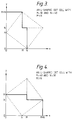
- Figure 3 shows how it is possible to take the square map of Figure 2 and, by relocating two triangular sections, construct an L-shape map of the same area that will also tessalate the plane.
- Figure 3 applies if M is less than N. If M is greater than N then the construction is as shown in Figure 4. It should be noted that the maximum dimension is always M + N and the other dimension is the greater of M and N.
- the map stored in the store 7 defines a number of full half-tone dot areas and, in the case of a square map, can be defined as having dimension K by K where K is the number of dots in either direction in the map.
- the map is thus defined by 3 parameters, K, M and N. It can be shown that to achieve ⁇ 1/2 degree precision in angle M or N need not exceed 64. Since one of the dimensions of the L-shaped map is M + N this means that the map need not exceed 128 x 128. This produces better than ⁇ 1% tolerance on the ruling.
- the value of K will usually be chosen empirically.
- each change of shape, ruling or angle requires a new map. This makes it desirable to generate the map contents during initialization of the output scanner. Furthermore, if all separations (typically 3 or 4) are to be imaged together then the same number of separate maps are required because it may be necessary to switch from to another in a matter of micro seconds. In one application this means that the store 7 must contain 128 Kbytes.
Landscapes
- Engineering & Computer Science (AREA)
- Multimedia (AREA)
- Signal Processing (AREA)
- Facsimile Image Signal Circuits (AREA)
- Facsimile Scanning Arrangements (AREA)
- Dot-Matrix Printers And Others (AREA)
- Color, Gradation (AREA)
- Fax Reproducing Arrangements (AREA)
Claims (7)
- Procédé de commande de l'exposition d'un support d'enregistrement à un faisceau de radiation pendant le déplacement de balayage relatif entre le support et le faisceau, dans lequel un signal d'image représentant le contenu en couleur d'une image et une carte de points en demi-teinte, précédemment créée sous un angle d'écran particulier, sont utilisés pour créer un signal binaire de commande du faisceau en balayant la carte en synchronisme avec le faisceau balayant le support d'enregistrement, et en comparant le signal d'image à la valeur instantanée sur la carte, le signal binaire de commande du faisceau étant créé en fonction du résultat de la comparaison, caractérisé en ce que la carte de points en demi-teinte définit un certain nombre de zones adjacentes de points en demi-teinte, chaque zone comportant un ensemble complet de seuils de points en demi-teinte dans lesquels le contenu en données est différent pour au moins certaines zones; en ce que chaque zone de la carte est balayée pour créer un signal de commande pour des zones correspondantes du support d'enregistrement; et en ce qu'avant de balayer le support d'enregistrement sous un angle d'écran particulier, la carte de points en demi-teinte est déterminée pour cet angle d'écran, de telle sorte que la carte des demi-teintes correspondant à chaque angle d'écran est balayée dans la même direction et avec les mêmes incréments.
- Procédé selon la revendication 1, dans lequel l'étape de détermination d'une carte de points en demi-teinte comporte la construction d'une carte de points en demi-teinte modifiée dont les côtés sont parallèles ou perpendiculaires à la direction de balayage, la carte modifiée présentant la forme d'un L dont les bras du L présentant des longueurs valant respectivement N + M et la plus grande des deux valeurs de N et de M, et où l'angle d'écran r est défini par: N/M = tan r.
- Procédé selon la revendication 1 ou la revendication 2, dans lequel le contenu en données est différent pour chaque zone de la carte de points en demi-teinte.
- Procédé selon l'une quelconque des revendications précédentes, dans lequel l'étape de détermination de la carte de points en demi-teinte comporte la rotation et la remise à l'échelle d'une carte de points en demi-teinte précédemment déterminée.
- Appareil de commande de l'exposition d'un support d'enregistrement (4) à un faisceau de radiation (3) pendant le déplacement de balayage relatif entre le support et le faisceau, pour enregistrer des séparations d'image en demi-teinte à des angles d'écran particuliers, l'appareil comportant un générateur (6) de signaux de commande; des moyens de commande (8, 9); et une mémoire (7) pour conserver une carte de points en demi-teinte précédemment créée sous la commande du moyen de commande (9), le générateur de signaux de commande répondant à un signal d'image représentant le contenu en couleur d'une image et à un signal provenant de la mémoire, pour créer un signal binaire de commande du faisceau en balayant la carte en synchronisme avec le faisceau balayant le support d'enregistrement, et en comparant le signal d'image avec la valeur en cours de la carte, le signal binaire de commande du faisceau étant créé en fonction du résultat de la comparaison, caractérisé en ce que la mémoire (7) est d'une taille suffisante pour permettre à la carte de points en demi-teinte de définir un certain nombre de zones adjacentes de points en demi-teinte, chaque zone comportant un jeu complet de seuils de points en demi-teinte dans lesquels le contenu en données d'au moins certaines zones est différent; en ce que le générateur (6) de signaux de commande répond à chaque région de la carte pour créer le signal de commande pour des zones adjacentes correspondantes du support d'enregistrement; en ce que le moyen de commande (8) balaye la carte de points en demi-teinte dans la même direction et avec les mêmes incréments pour tous les angles d'écran, et fournit des valeurs de carte correspondantes au générateur (6) de signaux de commande; et en ce qu'avant de balayer le support d'enregistrement à un angle d'écran particulier, le moyen de commande (9) détermine la carte correspondante de points en demi-teinte de telle sorte que la carte des demi-teintes correspondant à chaque angle d'écran soit balayée dans la même direction et avec les mêmes incréments.
- Appareil selon la revendication 5, dans lequel le moyen de commande comporte un générateur d'adresses (8) pour balayer la mémoire (7).
- Appareil selon la revendication 5 ou la revendication 6, dans lequel le générateur (6) de signaux de commande comporte un comparateur.
Applications Claiming Priority (2)
| Application Number | Priority Date | Filing Date | Title |
|---|---|---|---|
| GB9008318 | 1990-04-12 | ||
| GB909008318A GB9008318D0 (en) | 1990-04-12 | 1990-04-12 | Methods and apparatus for half-tone imaging |
Publications (2)
| Publication Number | Publication Date |
|---|---|
| EP0451995A1 EP0451995A1 (fr) | 1991-10-16 |
| EP0451995B1 true EP0451995B1 (fr) | 1995-09-27 |
Family
ID=10674336
Family Applications (1)
| Application Number | Title | Priority Date | Filing Date |
|---|---|---|---|
| EP91302720A Expired - Lifetime EP0451995B1 (fr) | 1990-04-12 | 1991-03-27 | Procédé et appareil pour la formation d'images en demi-teintes |
Country Status (5)
| Country | Link |
|---|---|
| US (1) | US5220432A (fr) |
| EP (1) | EP0451995B1 (fr) |
| JP (1) | JPH04227374A (fr) |
| DE (1) | DE69113309T2 (fr) |
| GB (1) | GB9008318D0 (fr) |
Families Citing this family (5)
| Publication number | Priority date | Publication date | Assignee | Title |
|---|---|---|---|---|
| US5542029A (en) * | 1993-09-30 | 1996-07-30 | Apple Computer, Inc. | System and method for halftoning using an overlapping threshold array |
| US5689623A (en) * | 1995-03-27 | 1997-11-18 | Optronics International Corporation | Spread spectrum digital screening |
| JP4198835B2 (ja) * | 1999-08-27 | 2008-12-17 | 株式会社沖データ | 書き込み装置、画像形成装置及びledヘッド |
| US7152524B2 (en) * | 2003-01-14 | 2006-12-26 | Picbags, L.P. | Golf bag having image thereon, systems and methods of forming same, and methods of using golf bag |
| US20090261004A1 (en) * | 2003-01-14 | 2009-10-22 | Picbags, L.P. | Combination System And Golf Bag |
Family Cites Families (10)
| Publication number | Priority date | Publication date | Assignee | Title |
|---|---|---|---|---|
| DE1901101A1 (de) * | 1969-01-10 | 1970-10-29 | Hell Rudolf Dr Ing Fa | Verfahren zur punkt- und zeilenweisen gerasterten Aufzeichnung der durch Abtastung von Halbtonbildern gewonnenen Bildsignale mit gegen die Aufzeichnungsrichtung gedrehtem Raster |
| US4084183A (en) * | 1970-03-18 | 1978-04-11 | Dr. Ing. Rudolf Hell Gmbh. | Method for the electro-optical reproduction of half-tone pictures |
| US4185304A (en) * | 1977-07-07 | 1980-01-22 | Xerox Corporation | Electronic halftone screening |
| JPS57120937A (en) * | 1981-01-21 | 1982-07-28 | Dainippon Screen Mfg Co Ltd | Formation of halftone plate image |
| JPS5880639A (ja) * | 1981-11-07 | 1983-05-14 | Dainippon Screen Mfg Co Ltd | 網目版画像の記録方法 |
| JPS58215654A (ja) * | 1982-06-09 | 1983-12-15 | Canon Inc | カラ−画像処理方法 |
| JPS5978353A (ja) * | 1982-10-28 | 1984-05-07 | Dainippon Screen Mfg Co Ltd | 網目版画像記録装置における網点形成方法 |
| JP2556486B2 (ja) * | 1986-11-14 | 1996-11-20 | キヤノン株式会社 | フィルム読取装置 |
| AU605298B2 (en) * | 1987-05-29 | 1991-01-10 | Digital Equipment Corporation | System for producing dithered images on asymmetric grids |
| EP0427380B1 (fr) * | 1989-11-08 | 1996-03-06 | Adobe Systems Inc. | Procédé pour la production d'images en demi-teintes |
-
1990
- 1990-04-12 GB GB909008318A patent/GB9008318D0/en active Pending
-
1991
- 1991-03-27 EP EP91302720A patent/EP0451995B1/fr not_active Expired - Lifetime
- 1991-03-27 DE DE69113309T patent/DE69113309T2/de not_active Expired - Fee Related
- 1991-04-11 JP JP3079014A patent/JPH04227374A/ja active Pending
- 1991-04-12 US US07/694,215 patent/US5220432A/en not_active Expired - Lifetime
Also Published As
| Publication number | Publication date |
|---|---|
| DE69113309D1 (de) | 1995-11-02 |
| GB9008318D0 (en) | 1990-06-13 |
| EP0451995A1 (fr) | 1991-10-16 |
| DE69113309T2 (de) | 1996-03-07 |
| JPH04227374A (ja) | 1992-08-17 |
| US5220432A (en) | 1993-06-15 |
Similar Documents
| Publication | Publication Date | Title |
|---|---|---|
| US4149183A (en) | Electronic halftone generator | |
| US4196451A (en) | Electronic halftone generator | |
| US5404411A (en) | Bitmap-image pattern matching apparatus for correcting bitmap errors in a printing system | |
| US5208871A (en) | Pixel quantization with adaptive error diffusion | |
| JPH07236059A (ja) | 超高感度印刷システム | |
| JPH07184071A (ja) | 超高感度印刷システム | |
| US5426519A (en) | Method and apparatus for implementing accurate angle screens | |
| US5479584A (en) | Enhanced fidelity reproduction of images with device independent numerical sample output | |
| EP0583776B1 (fr) | Filtre de trame ainsi que dispositif et procédé pour le générer | |
| EP0642259A2 (fr) | Trame de demi-teintes à modulation de fréquence et son procédé de fabrication | |
| US6301397B1 (en) | Systems and methods for rotating high addressability images | |
| EP0342845B1 (fr) | Création d'images en demi-teintes | |
| EP0642258B1 (fr) | Procédé pour obtenir une image tramée par modulation en fréquence | |
| EP1017018B1 (fr) | Procédé et appareil pour la rotation d'image à haute facilité d'adressage | |
| EP1067763B1 (fr) | Système et procédé pour obtenir des images à haute facilité d'adressage | |
| US5640191A (en) | Resolution transforming raster based imaging system and related transformation method | |
| EP1439690B1 (fr) | Processeur demi-tons avec sortie multi-bit échantillonée pour matrice de seuils | |
| US5220432A (en) | Methods and apparatus for half-tone imaging utilizing a rotated half-tone dot map | |
| US5638110A (en) | Two dimensional slope thresholding in a hyperacuity printer | |
| EP0457519B1 (fr) | Appareil pour la génération d'une reproduction tramée d'une image | |
| US6411745B1 (en) | Method and apparatus to reduce cross-interference in reproduction of scanned halftone images | |
| JP3112308B2 (ja) | 連続調整可能なラスタ解像度印刷方法 | |
| US7277201B2 (en) | Systems and methods for designing digital anamorphic line screens | |
| US6201560B1 (en) | Multibeam modulation driver for a hyperacuity printer | |
| EP0481812B1 (fr) | Procédé de conversion d'images utilisant la diffusion d'erreurs |
Legal Events
| Date | Code | Title | Description |
|---|---|---|---|
| PUAI | Public reference made under article 153(3) epc to a published international application that has entered the european phase |
Free format text: ORIGINAL CODE: 0009012 |
|
| AK | Designated contracting states |
Kind code of ref document: A1 Designated state(s): DE GB |
|
| 17P | Request for examination filed |
Effective date: 19920410 |
|
| RAP1 | Party data changed (applicant data changed or rights of an application transferred) |
Owner name: CROSFIELD ELECTRONICS LIMITED |
|
| 17Q | First examination report despatched |
Effective date: 19940323 |
|
| GRAA | (expected) grant |
Free format text: ORIGINAL CODE: 0009210 |
|
| AK | Designated contracting states |
Kind code of ref document: B1 Designated state(s): DE GB |
|
| REF | Corresponds to: |
Ref document number: 69113309 Country of ref document: DE Date of ref document: 19951102 |
|
| PLBE | No opposition filed within time limit |
Free format text: ORIGINAL CODE: 0009261 |
|
| STAA | Information on the status of an ep patent application or granted ep patent |
Free format text: STATUS: NO OPPOSITION FILED WITHIN TIME LIMIT |
|
| 26N | No opposition filed | ||
| REG | Reference to a national code |
Ref country code: GB Ref legal event code: 732E |
|
| REG | Reference to a national code |
Ref country code: GB Ref legal event code: IF02 |
|
| PGFP | Annual fee paid to national office [announced via postgrant information from national office to epo] |
Ref country code: GB Payment date: 20030326 Year of fee payment: 13 |
|
| PGFP | Annual fee paid to national office [announced via postgrant information from national office to epo] |
Ref country code: DE Payment date: 20030403 Year of fee payment: 13 |
|
| PG25 | Lapsed in a contracting state [announced via postgrant information from national office to epo] |
Ref country code: GB Free format text: LAPSE BECAUSE OF NON-PAYMENT OF DUE FEES Effective date: 20040327 |
|
| PG25 | Lapsed in a contracting state [announced via postgrant information from national office to epo] |
Ref country code: DE Free format text: LAPSE BECAUSE OF NON-PAYMENT OF DUE FEES Effective date: 20041001 |
|
| GBPC | Gb: european patent ceased through non-payment of renewal fee |
Effective date: 20040327 |