EP0451999A2 - Schaltmatrixgerät - Google Patents
Schaltmatrixgerät Download PDFInfo
- Publication number
- EP0451999A2 EP0451999A2 EP91302745A EP91302745A EP0451999A2 EP 0451999 A2 EP0451999 A2 EP 0451999A2 EP 91302745 A EP91302745 A EP 91302745A EP 91302745 A EP91302745 A EP 91302745A EP 0451999 A2 EP0451999 A2 EP 0451999A2
- Authority
- EP
- European Patent Office
- Prior art keywords
- matrix switcher
- units
- matrix
- output terminals
- input
- Prior art date
- Legal status (The legal status is an assumption and is not a legal conclusion. Google has not performed a legal analysis and makes no representation as to the accuracy of the status listed.)
- Withdrawn
Links
Images
Classifications
-
- H—ELECTRICITY
- H04—ELECTRIC COMMUNICATION TECHNIQUE
- H04Q—SELECTING
- H04Q3/00—Selecting arrangements
- H04Q3/42—Circuit arrangements for indirect selecting controlled by common circuits, e.g. register controller, marker
- H04Q3/52—Circuit arrangements for indirect selecting controlled by common circuits, e.g. register controller, marker using static devices in switching stages, e.g. electronic switching arrangements
- H04Q3/521—Circuit arrangements for indirect selecting controlled by common circuits, e.g. register controller, marker using static devices in switching stages, e.g. electronic switching arrangements using semiconductors in the switching stages
- H04Q3/523—Details
-
- H—ELECTRICITY
- H04—ELECTRIC COMMUNICATION TECHNIQUE
- H04H—BROADCAST COMMUNICATION
- H04H60/00—Arrangements for broadcast applications with a direct linking to broadcast information or broadcast space-time; Broadcast-related systems
- H04H60/02—Arrangements for generating broadcast information; Arrangements for generating broadcast-related information with a direct linking to broadcast information or to broadcast space-time; Arrangements for simultaneous generation of broadcast information and broadcast-related information
- H04H60/04—Studio equipment; Interconnection of studios
-
- H—ELECTRICITY
- H04—ELECTRIC COMMUNICATION TECHNIQUE
- H04N—PICTORIAL COMMUNICATION, e.g. TELEVISION
- H04N5/00—Details of television systems
- H04N5/222—Studio circuitry; Studio devices; Studio equipment
- H04N5/262—Studio circuits, e.g. for mixing, switching-over, change of character of image, other special effects ; Cameras specially adapted for the electronic generation of special effects
- H04N5/268—Signal distribution or switching
Definitions
- This invention relates to a matrix switcher apparatus adapted to output, from desired output terminals, input signals delivered through a plurality of input terminals.
- a switcher apparatus In, e.g., television studios or broadcasting stations, so-called a switcher apparatus is used in order to make switching between various such as audio signals or video signals, etc.
- a switcher apparatus of a structure such that a first switcher for selecting one video signal from a plurality of input video signals and a second switcher for selecting one video signal from the selected input video signal and a plurality of specific input video signals to output the selected one are cascade-connected, and a switcher apparatus provided with means for switching between the control circuit for the first switcher and the control circuit for the second switcher.
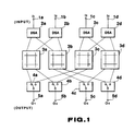
- a matrix switcher apparatus As a switcher apparatus of M ⁇ N adapted to carry out switching selection of, e.g., N video signals from M input video signals (hereinafter referred to as a matrix switcher apparatus), a matrix apparatus of a structure, e.g., a shown in FIG. 1 is known. The operation of the matrix switcher apparatus of the structure shown in FIG. 1 will now be briefly described.
- Video signals I1 to I4 respectively delivered through input terminals 1a to 1d are delivered to video distributor amplifiers (hereinafter referred to as DSAs) 2a to 2d. These DSAs 2a to 2d are amplifiers to distribute a video signal into two signals. Video signals I1 and I2 from the DSAs 2a and 2b are delivered to a matrix switcher unit 3a and a matrix switcher unit 3b. Further, video signals I3 and I4 from DSAs 2c and 2d are delivered to a matrix switcher unit 3c and a matrix switcher unit 3d.
- DSAs video distributor amplifiers
- the above-mentioned matrix switcher units 3a to 3d are each comprised of, e.g., a matrix switcher unit of 2 ⁇ 2.
- the matrix switcher unit 3a switches between video signals I1 and I2 from DSAs 2a and 2b to deliver a switched one to change-over switches 4a and 4b.
- the matrix switcher unit 63b switches between video signals I1 and I2 from DSAs 2a and 2b to deliver a switched one to change-over switches 4c and 4d.
- the matrix switcher unit 3c switches between video signals I3 and I4 from DSAs 2c and 2d to deliver a switched one to the change-over switches 4a and 4b.
- the matrix switcher unit 63d switches between video signals I3 and I4 from DSAs 2c and 2d to deliver a switched one to the change-over switches 4c and 4d.
- the change-over switch 4a selects one of video signals from the matrix switcher units 3a and 3c to output a selected one to an output terminal 5a as a video signal O1.
- the change-over switch 4b selects one of video signals from the matrix switcher units 3a and 3c to output a selected one to an output terminal 5b as a video signal O2
- the change-over switch 4c selects one of video signals from the matrix switcher units 3b and 3d to output a selected one to an output terminal 5c as a video signal O3.
- the change-over switch 4d selects one of video signals from the matrix switcher units 3b and 3d to output a selected one to an output terminal 5d as a video signal O4.
- video signals arbitrarily selected from four video signals I1 to I4 respectively delivered through input terminals 1a to 1d are outputted to the output terminals 5a to 5d. Since respective video signals O1 to O4 taken out from these output terminals 5a to 5d go by way of DSAs 2 having the same delay characteristics, respectively, matrix switcher units 3 having the same delay characteristics, respectively, and change-over switches 4 having the same delay characteristics, respectively, delay times of respective video signals O1 to O4 are the same even if they pass through any path (route), resulting in the fact that phases of respective output video signals O1 signals O4 are the same.
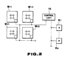
- matrix switcher units M11 to M22 are each comprised of, e.g., a small scale matrix switcher unit as described above.
- the control unit 50 was operative to receive a switching request signal from so-called remote controls R1 to R k to control, in a centralized manner, respective matrix switcher units M11 to M22 by using a control program stored in the control unit 10.
- control programs for exclusive use are required every scales of the matrix switcher apparatuses.
- development of control programs in conformity with scales of matrix switcher apparatuses was required.
- this invention has been made, and its object is to provide a matrix switcher apparatus which can constitute small scale to large scale matrix switcher apparatuses by using the same matrix switcher unit without necessitating the control unit 10 for concentrically control respective matrix switcher units M11 to M22 as described above, and which can install more matrix switcher units with ease, thus permitting the number of input/output signals to be easily increased.
- a plurality of matrix switcher units each including a plurality of first input terminals, a plurality of second input terminals, a plurality of first output terminals, and a plurality of second output terminals.
- Such a plurality of matrix switcher units are arranged in a matrix form. Between adjacent matrix switcher units, a plurality of first input terminals and a plurality of first output terminals are connected, and a plurality second input terminals and a plurality of second output terminals are connected.
- control means for storing ID information to identify first input terminals and second output terminals, and for controlling cross points of the matrix switcher units are provided every matrix switcher units to deliver selective instruction signals for signal input and output terminals to respective control means to control ON/OFF of cross points on the basis of selective instruction signals in respective control means, thereby making it possible to constitute a matrix switcher apparatus of M inputs ⁇ N outputs as a whole, thus to carry out switching selection of a plurality of input signals to output selected ones to desired output terminals.
- control circuits are respectively provided in the matrix switcher units to carry out distributed processing, thereby making it possible to constitute small scale to large scale matrix switcher apparatuses by using the same matrix switcher units.
- user can purchase a matrix switcher apparatus of a desired scale at the minimum cost.
- an approach is employed to additionally provide a matrix switcher unit in the matrix switcher apparatus once installed, thereby making it possible to increase the number of input/output signals with ease without such a troublesomeness to change the control program of a centerized control unit as encountered with conventional matrix switcher apparatus.
- wiring in this enlargement may be attained by directly connecting matrix switcher units. Thus, enlargement can be carried out with ease.
- a matrix switcher apparatus of, e.g., 4 inputs ⁇ 4 outputs (hereinafter referred to as 4 ⁇ 4) is of a structure such that four matrix switcher units M11 to M22 of 2 ⁇ 2 are arranged in a matrix form (lengthwise and breadthwise).
- the above-mentioned respective matrix switcher units M11 to M22 have the same circuit configuration, i.e., include two first input terminals TI11 and TI12, two second input terminals TI21 and TI22, two first output terminals TO11 and TO12, and two second output terminals TO21 and TO22, respectively. Further, the above-mentioned first input terminals TI11 and TI12 are connected to the input terminals of buffers B11 and B12, respectively, and the output terminals of the buffers B11 and B12 are connected to the first output terminals TO11 and TO12, respectively.
- the second input terminals TI21 and TI22 are connected to the input terminals of buffers B21 and B22, respectively, and the output terminals of the buffers B21 and B22 are connected to switches X10 and X20 expressed by intersections of signal lines, so-called cross points, respectively. Outputs from the switches X10 and X20 are taken out from the second output terminals TO21 and TO22, respectively.
- respective cross points of signal lines in the matrix switcher units M11 to M22 represent switches X11, X12, X21 and X22.
- These switches X11 to X22 serve to carry out switching to allow signal lines in a longitudinal direction and signal lines in a lateral direction within the matrix switcher units to be placed in a connected (ON) state or a cut off (OFF) state.
- the above-mentioned matrix switcher units M11 to M22 carry out switching selection of four input signals in total respectively delivered through the first input terminals TI11 and TI12 and the second input terminals TI21 and TI22 to arbitrarily output selected ones to the respective second output terminals TO21 and TO22, and to output two input signals delivered through the first input terminals TI11 and TO12 to the first output terminals TO11 and TO12, respectively.
- the matrix switcher units M11 to M22 output, from desired output terminals TO21 and TO22, four input signals respectively delivered through the input terminals TI11, TI12, TI21 and TI22, and output two input signals delivered through the first input terminals TO11 and TI12 to the first output terminals TO11 and TO12, respectively.
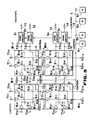
- the matrix switcher units M11 to M22 constructed as described above are arranged in a matrix form as shown in FIG. 3. Between adjacent matrix switcher units, the first output terminals TO11 and TO12 of a matrix switcher unit and the first input terminals TI11 and TI12 of the adjacent matrix switcher unit are connected, respectively, and the second output terminals TO21 and TO22 and the second input terminals TI21 and TI22 of the adjacent matrix switcher unit are connected, respectively. Thus, a matrix switcher apparatus of 4 ⁇ 4 is constituted. As a result, as shown in FIG.
- the matrix switcher apparatus constructed above includes the second input terminals TI21 and TI22 capable of cascade-connecting a new matrix switcher unit at the matrix switcher units M11 and M21, respectively, and includes the first output terminals TO11 and TO12 at the matrix switcher units M21 and M22, respectively, it is possible to install more matrix switcher units with ease.
- the second output terminals TO21 and TO22 of the matrix switcher units M12 and M22 are connected to synchronization (SYNC) circuit S1 to S4, respectively.
- SYNC circuit S1 to S4 are circuits for providing synchronization of so-called subframe, frame, and block, etc. of an input signals, e.g., a digital video signal.
- These circuits serve to allow phases and various synchronizations of, e.g., respective digital video signals delivered through the output terminals TO21 and TO22 of the matrix switcher units M12 and M22 to be in correspondence with each other by using, e.g., a clock signal CK, and various synchronization signals SYNC delivered through the terminals 15 to output, as output signals O1 to O4, through output terminals 11 to 14, digital video signals of which phases and various synchronizations are in correspondence with each other.
- an input signal that the matrix switcher apparatus carries out switching is not limited to the digital video signal mentioned above, but may be a digital signal such as a digital audio signal.
- the matrix switcher units M11 to M22 include control circuits C for controlling the switches X10, X11, X12, X20, X21, and X22 in the matrix switcher units M11 to M22, respectively.
- Respective control circuits C of the matrix switcher units M11 to M22 are connected by way of a single control line L.
- remote controls R1 to R4 for carrying out remote are connected.
- ID identification information for identifying input signals delivered to the respective matrix switcher units M11 to M22 and output signals that the respective matrix switcher units M11 to M22 output are stored.
- ID identification information
- input signals I1 and I2 are delivered to the matrix switcher unit M11, and the matrix switcher unit M11 outputs each of output signals O1 and O2 through the matrix switcher unit M12 and the SYNC circuits S1 and S2.
- ID (I1, I2 : O1, O2) is allotted as ID of the matrix switcher unit M11.
- ID (I3, I4 : O1, O2) are allotted to the matrix switcher unit M12
- ID (I1, I2 : O3, O4) is allotted to the matrix switcher unit M21
- ID (I3, I4 : O3, O4) is allotted to the matrix switcher unit M22.
- the above-mentioned remote controls R1 to R4 correspond to output terminals 11 to 14, respectively.
- the remote control R1 serves to carry out selective control of input signals I1 to I4 outputted as an output signal O1 from the output terminal I.
- matrix switcher units M11 to M22 each including two first input terminals TI11 and TI12, two second input terminals TI21 and TI22, two first output terminals TO11 and TO12, and two second output terminals TO21 and TO22.
- These matrix switcher units M11 to M22 are arranged in a matrix form. Between adjacent matrix switcher units, two first input terminals TI11 and TI12 and two first output terminals TO11 and TO12 are connected, and two second input terminals TI21 AND TI22 and two second output terminals TO21 and TO22 are connected to thereby constitute a matrix switcher apparatus of 4 ⁇ 4 as a whole.
- the control circuits C provided every matrix switcher units M11 to M22 are used as control means for storing identification information for identifying the first terminals TI11 and TI12 and the second output terminals TO21 and TO22, and for controlling ON/OFF of cross points of the matrix switcher units, i.e., switches X10, X11, X12, X20, X21, and X22.
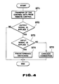
- control data for making an instruction to carry out switching selection of input signals I1 to I4 to output selected ones to corresponding ones of output terminals 11 to 14 is transferred to each of control circuit C of the matrix switcher units M11 to M22.
- control data to output the input signal I1 as the output signal O1 to the output terminal 11 (hereinafter represented as [I1 ⁇ O1]) is transferred to each of control circuits C of the matrix switcher units M11 to M22 by means of the remote control R1.
- each of the control circuits C of the matrix switcher units M11 to M22 makes comparison between the above-mentioned allotted IDs and the received control data to judge whether or not an output signal instructed by the control data corresponds to output signals subjected to switching by each of the matrix switcher units M11 to M22 and outputted therefrom to proceed to step ST3 when the former corresponds to the latter, and to end the operation while maintaining the present state.
- each of the control circuits C of the matrix switcher units M11 to M22 makes comparison between the ID and the control data [I1 ⁇ O1].
- each of the control circuits C of the matrix switcher units M11 and M12 to which the output signal O1 is allotted judge that there is correspondence to proceed to step ST3.
- each of the control circuits C of other matrix switcher units M21 and M22 judges that there is no correspondence to end the operation while maintaining the present state.
- each of the control circuits C of the matrix switcher units M11 to M22 makes comparison between the ID and the control data to judge whether or not an input signal instructed by control data corresponds to an input signal delivered to each of the matrix switcher units M11 to M22 to proceed to step ST4 when the former corresponds to the latter, and to proceed to step ST5 when the former does not correspond to the latter.
- each of the control circuits C of the matrix switcher units M11 and M12 makes comparison between the ID and the control data [I1 ⁇ O1].
- the control circuit C of the matrix switcher unit M11 to which the input signal I1 is allotted judges that there is correspondence to proceed to the step ST4.
- the control circuit C of the matrix switcher unit M12 judges that there is no correspondence to proceed to the step ST5.
- respective control circuits C of the matrix switcher units M11 to M22 control the switches X11 to X22 on the basis of the control data.
- the control circuit C of the matrix switcher unit M11 controls the switch X11 of the matrix switcher unit M11 shown in FIG. 3 so that it is in an ON state to end the operation.
- respective control circuits C of the matrix switcher units M11 to M22 control the switches X10 and X20 for cascade-connecting matrix switcher units.
- the control circuit C of the matrix switcher unit M12 controls the switch X10 of the matrix switcher unit M12 shown in FIG. 3 for cascade-connecting matrix switcher units so that it is in an ON state to end the operation.
- an input signal I1 delivered through the input terminal TI11 of the matrix switcher unit M11 is delivered to the SYNC circuit S1 through the switch X11 of the matrix switcher unit M11 and the switch X10 of the matrix switcher unit M12, and is subjected to synchronization. Thereafter, that input signal is outputted from the output terminal 11 as an output signal O1.
- control data [I2 ⁇ O1] is transferred to each of the control circuits C of the matrix switcher units M11 to M22 by means of the remote control R1.
- control circuit C of the matrix switcher unit M11 controls the switch X11 in the matrix switcher unit M11 so that it is an OFF state, and to control the switch X12 so that it is an ON state.
- the control circuit C of the matrix switcher unit M12 controls the switch X10 in the matrix switcher unit M12 so that it is in an ON state for a second time, i.e., maintains the present state. It is to be noted that, at the step ST2, respective control circuits of the matrix switcher units M21 and M22 effects a control to maintain the present state because they have no corresponding output signal.
- remote controls R2 to R4 corresponding to respective output terminals 2 to 4 may be employed to control respective matrix switcher units M11 to M22 through a single control line L, thereby making it possible to arbitrarily select input signals I1 to I4 to output selected ones from respective output terminals 12 to 14.
- remote controls R1 to R4 correspond to output terminals 11 to 14, respectively.
- an output signal O1 outputted from the output terminal 11 may be controlled from other remote controls R2 and R3.
- matrix switcher units M11 to M22 each including two first input terminals TI11 and TI12, two second input terminals TI21 and TI22, two first output terminals TO11 and TO12, and two second output terminals TO21 and TO22. These matrix switcher units M11 to M22 are arranged in a matrix form. Between adjacent matrix switcher units, first input terminals TI11 and TI12 and first output terminals TO11 and TO12 are connected, and second input terminals TI21 and TI22 and second output terminals TO21 and TO22 are connected.
- control circuits C for storing ID information to identify first input terminals TI11 and TI12 and second output terminals TO21 and TO22, and for controlling cross points X10, X11, X12, X20, X21 and X22 of the matrix switcher units are provided every matrix switcher units M11 to M22 to deliver selective instruction signals for signal input and output terminals to respective control circuits C to control individually, i.e., in a distributed manner, ON/OFF of cross points X10, X11, X12, X20, X21 and X22 on the basis of selective instruction signals in the respective control circuits C, thereby making it possible to constitute a matrix switcher apparatus of 4 inputs ⁇ 4 outputs as a whole without necessitating a centralized control apparatus as in the prior art.
- control circuits C are provided in the respective matrix switcher units M11 to M22 to carry out distributed processing, thereby making it possible to constitute small scale to large scale matrix switcher apparatuses by using the same matrix switcher units. Furthermore, an arrangement is employed to additionally provide a matrix switcher unit in a matrix switcher apparatus once installed to set simple information of an input signal added to the remote control R, thereby making it possible to increase the number of output signals with ease without such a troublesomeness to change a control program of a centralized control unit as encountered with a conventional matrix switcher apparatus.
- the matrix switcher unit is caused to be of structure of 32 inputs ⁇ 32 outputs to use a single matrix switcher unit of such a structure, thereby making it possible to constitute a matrix switcher apparatus of 32 inputs ⁇ 32 outputs.
- the above-mentioned matrix switcher units are arranged in the form of a matrix of 16 ⁇ 16
- a matrix switcher apparatus of 512 inputs ⁇ 512 outputs can be constituted without changing the control program.
- SYNC circuits S1 to S4 are used in order to synchronizations, etc. of respective output signals O1 to O4 outputted from the output terminals 1 to 4 to be in correspondence with each other, e.g., in the case where an input signal delivered to the matrix switcher apparatus is a digital video signal, and that a device connected to the output terminal 11 to 14 is a digital VTR (video tape recorder), etc, an approach may be employed to use the SYNC circuit provided in the digital VTR, etc. and to omit SYNC circuits S1 to S4.
Landscapes
- Engineering & Computer Science (AREA)
- Signal Processing (AREA)
- Computer Networks & Wireless Communication (AREA)
- Multimedia (AREA)
- Studio Circuits (AREA)
Applications Claiming Priority (2)
| Application Number | Priority Date | Filing Date | Title |
|---|---|---|---|
| JP8031090A JP2775975B2 (ja) | 1990-03-28 | 1990-03-28 | マトリックススイッチャ装置 |
| JP80310/90 | 1990-03-28 |
Publications (2)
| Publication Number | Publication Date |
|---|---|
| EP0451999A2 true EP0451999A2 (de) | 1991-10-16 |
| EP0451999A3 EP0451999A3 (en) | 1992-12-09 |
Family
ID=13714694
Family Applications (1)
| Application Number | Title | Priority Date | Filing Date |
|---|---|---|---|
| EP19910302745 Withdrawn EP0451999A3 (en) | 1990-03-28 | 1991-03-28 | Matrix switcher apparatus |
Country Status (2)
| Country | Link |
|---|---|
| EP (1) | EP0451999A3 (de) |
| JP (1) | JP2775975B2 (de) |
Cited By (4)
| Publication number | Priority date | Publication date | Assignee | Title |
|---|---|---|---|---|
| GB2261795A (en) * | 1991-11-22 | 1993-05-26 | Motorola Israel Ltd | Signal routing |
| FR2700432A1 (fr) * | 1993-01-13 | 1994-07-13 | Philips Electronics Nv | Dispositif commutateur de signaux de télévision pour une distribution par câble. |
| WO1998011756A1 (en) * | 1996-09-11 | 1998-03-19 | Gennum Corporation | Crosspoint switch |
| US5818349A (en) * | 1990-11-15 | 1998-10-06 | Nvision, Inc. | Switch composed of identical switch modules |
Family Cites Families (2)
| Publication number | Priority date | Publication date | Assignee | Title |
|---|---|---|---|---|
| JPS59163922A (ja) * | 1983-03-08 | 1984-09-17 | Nec Corp | N対2伝送路切替スイツチ |
| JPS60192435A (ja) * | 1984-03-14 | 1985-09-30 | Nec Corp | 放送局におけるスイツチヤ−制御方式 |
-
1990
- 1990-03-28 JP JP8031090A patent/JP2775975B2/ja not_active Expired - Lifetime
-
1991
- 1991-03-28 EP EP19910302745 patent/EP0451999A3/en not_active Withdrawn
Cited By (5)
| Publication number | Priority date | Publication date | Assignee | Title |
|---|---|---|---|---|
| US5818349A (en) * | 1990-11-15 | 1998-10-06 | Nvision, Inc. | Switch composed of identical switch modules |
| GB2261795A (en) * | 1991-11-22 | 1993-05-26 | Motorola Israel Ltd | Signal routing |
| FR2700432A1 (fr) * | 1993-01-13 | 1994-07-13 | Philips Electronics Nv | Dispositif commutateur de signaux de télévision pour une distribution par câble. |
| EP0606943A1 (de) * | 1993-01-13 | 1994-07-20 | Philips Electronique Grand Public | Schalteinrichtung zum Schalten von Fernsehsignalen für Kabelverteilungssystem |
| WO1998011756A1 (en) * | 1996-09-11 | 1998-03-19 | Gennum Corporation | Crosspoint switch |
Also Published As
| Publication number | Publication date |
|---|---|
| JP2775975B2 (ja) | 1998-07-16 |
| JPH03278776A (ja) | 1991-12-10 |
| EP0451999A3 (en) | 1992-12-09 |
Similar Documents
| Publication | Publication Date | Title |
|---|---|---|
| EP0725490B1 (de) | Steueranordnung für ein Aufzeichnungs- und Wiedergabegerät | |
| US5343193A (en) | Matrix switcher apparatus | |
| EP0039585A1 (de) | Steuereinrichtung für Lichtanlagen in Theatern | |
| US5296848A (en) | Method and apparatus for triggering an automatic transmission | |
| EP0451999A2 (de) | Schaltmatrixgerät | |
| EP0608048B1 (de) | Vorrichtung und Verfahren zur Auswahl von Signalleitungen zur Verbindung mit einer Mehrzahl von Audio-Videogeräten | |
| JP2775974B2 (ja) | マトリックススイッチャ装置 | |
| US20050117574A1 (en) | Data transmission system, terminal device, data transmission method, and recording medium | |
| JP2550251Y2 (ja) | デジタルオーデイオミキサ | |
| JPH02185782A (ja) | テレビジョン信号機器割当てマトリックス | |
| JP2941301B2 (ja) | 放送設備装置 | |
| JPH0629952A (ja) | 時分割多重回線のcrcチェック方式 | |
| JP2785281B2 (ja) | テレビジョンシステム | |
| JP3821242B2 (ja) | ミキシング装置の送り返し回路 | |
| JPH05316214A (ja) | データシミュレート装置 | |
| JPH11202911A (ja) | プログラマブルコントローラ用インタフェースユニット | |
| JPH0888611A (ja) | 映像音声切換制御装置 | |
| JPS6043550B2 (ja) | 通信回線制御装置 | |
| JPH0535516B2 (de) | ||
| JPS6188633A (ja) | 電子スイツチ | |
| JPH02298174A (ja) | 映像分配装置 | |
| JP2008011440A (ja) | 番組送出設備および伝送路切替方法 | |
| JPS58123245A (ja) | 情報伝送システム | |
| Halton et al. | Paper 4 The design of wide area equipment | |
| JPH0470023A (ja) | 番組プログラム送出装置 |
Legal Events
| Date | Code | Title | Description |
|---|---|---|---|
| PUAI | Public reference made under article 153(3) epc to a published international application that has entered the european phase |
Free format text: ORIGINAL CODE: 0009012 |
|
| AK | Designated contracting states |
Kind code of ref document: A2 Designated state(s): DE FR GB |
|
| PUAL | Search report despatched |
Free format text: ORIGINAL CODE: 0009013 |
|
| AK | Designated contracting states |
Kind code of ref document: A3 Designated state(s): DE FR GB |
|
| STAA | Information on the status of an ep patent application or granted ep patent |
Free format text: STATUS: THE APPLICATION IS DEEMED TO BE WITHDRAWN |
|
| 18D | Application deemed to be withdrawn |
Effective date: 19930610 |