EP0452099A2 - Unité de division - Google Patents
Unité de division Download PDFInfo
- Publication number
- EP0452099A2 EP0452099A2 EP91303132A EP91303132A EP0452099A2 EP 0452099 A2 EP0452099 A2 EP 0452099A2 EP 91303132 A EP91303132 A EP 91303132A EP 91303132 A EP91303132 A EP 91303132A EP 0452099 A2 EP0452099 A2 EP 0452099A2
- Authority
- EP
- European Patent Office
- Prior art keywords
- divisor
- partial remainder
- quotient digit
- interval
- selecting
- Prior art date
- Legal status (The legal status is an assumption and is not a legal conclusion. Google has not performed a legal analysis and makes no representation as to the accuracy of the status listed.)
- Withdrawn
Links
Images









Classifications
-
- G—PHYSICS
- G06—COMPUTING OR CALCULATING; COUNTING
- G06F—ELECTRIC DIGITAL DATA PROCESSING
- G06F7/00—Methods or arrangements for processing data by operating upon the order or content of the data handled
- G06F7/38—Methods or arrangements for performing computations using exclusively denominational number representation, e.g. using binary, ternary, decimal representation
- G06F7/48—Methods or arrangements for performing computations using exclusively denominational number representation, e.g. using binary, ternary, decimal representation using non-contact-making devices, e.g. tube, solid state device; using unspecified devices
- G06F7/52—Multiplying; Dividing
- G06F7/535—Dividing only
-
- G—PHYSICS
- G06—COMPUTING OR CALCULATING; COUNTING
- G06F—ELECTRIC DIGITAL DATA PROCESSING
- G06F7/00—Methods or arrangements for processing data by operating upon the order or content of the data handled
- G06F7/38—Methods or arrangements for performing computations using exclusively denominational number representation, e.g. using binary, ternary, decimal representation
- G06F7/48—Methods or arrangements for performing computations using exclusively denominational number representation, e.g. using binary, ternary, decimal representation using non-contact-making devices, e.g. tube, solid state device; using unspecified devices
- G06F7/52—Multiplying; Dividing
- G06F7/535—Dividing only
- G06F7/537—Reduction of the number of iteration steps or stages, e.g. using the Sweeny-Robertson-Tocher [SRT] algorithm
- G06F7/5375—Non restoring calculation, where each digit is either negative, zero or positive, e.g. SRT
Definitions
- This invention relates to a divider unit for executing a division in which a dividend and a divisor are both fixed-point parts of a floating-point number or a division in which a dividend and a divisor are both fixed-point numbers, the divider unit being applied in an information processor or the like.
- a division procedure generally takes much longer than an addition, subtraction or multiplication procedure. Executing such division procedure at a high speed cannot be realized without a huge-scale hardware.
- R (n+2) will be referred to simply as the final remainder, hereinafter.
- the following algorithm is a radix-4 case.
- the quotient Q n is obtained two digits by two digits. Each two digits are at the j-1'th and the j'th binary places in the binary representation and form a quotient digit q j .
- a quotient from the first to the j'th binary places is referred to as Q j .
- a value obtained by multiplying a partial remainder by 2 j is represented by R (j) .
- R (j) is used to obtain the quotient digit q j and will be referred to simply as the partial remainder, hereinafter.
- the value at the i'th binary place of the partial remainder R (j) expressed in the two's complement representation is referred to as A i .
- a value at the i'th binary place of the divisor d is referred to as M i .
- A0 indicates a sign in the two's complement representation.
- the partial remainder R (j) and the quotient digit q j are expressed in the redundant binary representation.
- each digit in the binary representation is expressed by two bits: a sign bit and an absolute value bit.
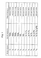
- Fig. 1 shows a divisor interval selection logic for selecting one interval which a divisor d belongs to out of a plurality of intervals bordered by specified values.
- Variables D1 through D11 represent the operation results obtained by the logical expressions shown in Fig. 1. Only one of the variables D1 through D11 is set to be 1.
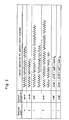
- Fig. 2 shows a quotient digit selection logic for selecting a quotient digit q j based on the variables D1 through D11 and the partial remainder R (j) .
- Variables zeroP, etc. represent the operation results obtained by the logical expressions shown in Fig. 2. Only one of the variables is set to be 1, and the corresponding quotient digit to the above one variable is selected.
- each bar above the variable means logical NOT.
- each bar above the figure in the quotient digit column indicates that the figure below the bar is negative. For instance, 1 means -1.
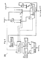
- Fig. 3 is a block diagram of a conceivable divider unit 100 for executing a division using the above algorithm.
- 1 refers to a divisor interval selection circuit for selecting one interval which the divisor d belongs to out of a plurality of intervals bordered by specified values based on M2, M3 and M4 in accordance with Fig. 1.
- a 3 refers to a quotient digit selection circuit for selecting one value as a quotient digit q j out of values -2, -1, 0, 1 and 2, of which absolute values are each represented in two bits. The selection is done based on the selection result of the circuit 1 and A0 trough A6 in accordance with Fig. 2.
- A0 trough A6 are obtained from a partial remainder R (j) outputted by a subsequent partial remainder generation circuit 17 (will be described later in detail).
- A0 is a sign of a value obtained by converting the upper six digits of the partial remainder R (j) into the two's complement representation.
- A1 trough A6 are values at the first trough the sixth binary places of the above value.
- the circuit 3 is to output a value 1 as a quotient digit q0 on an initial stage of the division.
- the circuit 3 is also to send a selection command and an addition/subtraction command to a divisor's multiple selection circuit 13 (will be described later in detail) and a subsequent partial remainder generation circuit 17.
- 5 refers to a negative quotient digit storage circuit for storing the absolute value of the quotient digit q j if the quotient digit q j is negative and storing the value 0 if not. Again, either value is stored at a digit position corresponding to the loop in which the storage is executed.
- the divisor's multiple selection circuit 13 is for outputting the product of the absolute value of the quotient digit q j and the divisor d (namely, the divisor d, the double of the divisor d or 0) in response to the selection command from the circuit 3.
- the subsequent partial remainder generation circuit 17 is for subtracting the divisor d from a dividend R (0) , both normalized by a normalization circuit (not shown), and outputting the subtraction result as a first partial remainder R (2) on the initial stage of the division.
- the circuit 17 is then to subtract the value sent by the circuit 13 from the quadruple of the partial remainder R (j) if the quotient digit q j is positive and add the above value and the above quadruple if the quotient digit q j is negative, in response to the addition/subtraction command from the circuit 3.
- the divider unit 100 having the above construction executes the division in the following way.
- the subsequent partial remainder generation circuit 17 subtracts the divisor d from the dividend R (0) and outputs the first partial remainder R (2) .
- the quotient digit selection circuit 3 outputs the value 1 as the quotient digit q0 (the value at ones place in the binary representation) and stores the above value 1 in the positive quotient digit storage circuit 4.
- the divisor interval selection circuit 1 decodes M2 through M4 in accordance with Fig. 1 and then selects the interval which the divisor d belongs to. Such selection is done only once on the initial stage of the division, and the selection result is retained until the division is finished.
- the quotient digit selection circuit 3 converts the upper six digits of the first partial remainder R(2) sent by the circuit 17 into the two's complement representation, whereby obtaining A0 through A6. Based on A0 through A6 and the selection result of the circuit 1, the circuit 3 selects one value as a quotient digit q2 out of -2, -1, 0, 1 and 2 in accordance with Fig. 2 and outputs the selected value. As mentioned before, the values -2, -1, 0, 1 and 2 each have an absolute value represented in two bits.
- the positive quotient digit storage circuit 4 On receiving the quotient digit q2 from the circuit 3, the positive quotient digit storage circuit 4 stores the absolute value of the quotient digit q2 at a digit position in the circuit 4 if the quotient digit q2 is positive, the digit position corresponding to a first loop. If the quotient digit q2 is not positive, the circuit 4 stores 0 at the same digit position.
- the negative quotient digit storage circuit 5 stores the absolute value of the quotient digit q2 at a digit position in the circuit 5 if the quotient digit q2 is negative, the digit position corresponding to the first loop. If the quotient digit q2 is not negative, the circuit 5 stores 0 at the same digit position.
- the divisor's multiple selection circuit 13 outputs the product of the absolute value of the quotient digit q2 and the divisor d in response to the selection command from the circuit 3.
- the subsequent partial remainder generation circuit 17 subtracts the value sent by the circuit 13 from the quadruple of the partial remainder R (2) if the quotient digit q2 is positive and adds the above value and the above quadruple if the quotient digit q2 is negative, whereby outputting a second partial remainder R (4) . Then, the operation goes back to 3) for the next loop, wherein R (4) is used instead of R (2) . 7) The above 3) to 6) is repeated n/2 times (the figures in binary places are counted as one) while incrementing each superscript and subscript by two.
- each quotient digit q j is obtained in the redundant binary representation, and the quotient digit q j is stored in the circuit 4 or 5 depending on the sign thereof. Then, a final remainder R (n+2) is outputted from the circuit 17.
- the quotient conversion circuit 6 subtracts the value stored in the circuit 5 from the value stored in the circuit 4 and converts the subtraction result into the two's complement representation. If the final remainder R (n+2) is negative, the circuit 6 subtracts a value 1 at the lowest bit of the above subtraction result in the two's complement representation, whereby the quotient Q n is obtained. If necessary, the circuit 6 also converts the final remainder R (n+2) into the two's complement representation in the same manner by a final remainder compensation circuit (not shown), and if the obtained value is negative, adds the divisor d thereto.
- the times the operation of the loop is repeated is approximately as half as in other types of divider units which are designed to execute the SRT division of radix-2 cases or the nonrestoring division. Further, since the subsequent partial remainder generation circuit 17 is controlled to operate in the redundant binary scheme, which requires no carry propagation, the operation time of each loop is shortened. As a result of the above two advantages, the above divider unit 100 executes the division nearly twice as fast as the above other types of divider units.
- the quotient digit is selected out of -3, -2, -1, 0, 1, 2 and 3.
- the quotient digit is selected only out of -2, -1, 0, 1 and 2.
- the circuit for obtaining the product of the quotient digit and the divisor comprises only two circuits: the divisor's double generation circuit 10 and the divisor's multiple selection circuit 13. As a result, simple hardware and high-speed execution are realized.
- the above divider unit 100 has the following problem.
- the quotient digit selection logic is complicated enough to require a quotient digit selection decoder for decoding a lot of upper bits of the partial remainder and the divisor.
- the addition of such a decoder enlarges the hardware of the quotient digit selection circuit 3 and prolongs the quotient digit selection time.
- this invention has an object of offering a divider unit for executing a division at a much higher speed than the conventional units by a simpler quotient digit selection logic while keeping the hardware compact.
- a divider unit for executing a high radix division using a partial remainder expressed in the two's complement representation, the unit comprising a quotient digit selecting device for selecting one quotient digit out of all quotient digits obtainable under an applied radix based on values of a part of upper digits of a divisor and of a part of upper digits of a partial remainder and on a sign of the partial remainder; a plurality of divisor's multiple generating devices, each for generating at least one of a value 0 and another value obtained by multiplying the divisor with 2 j , where j is an integer; and an adding and subtracting device having at least three inputs for selectively executing an addition and a subtraction using outputs from the divisor's multiple generating devices and a value obtained by multiplying the partial remainder by the value of the radix, whereby to generate another partial remainder.
- a divider unit for executing a high radix division using a partial remainder expressed in the redundant binary representation, the unit comprising a quotient digit selecting device for selecting one quotient digit out of all quotient digits obtainable under an applied radix based on values of a part of upper digits of a divisor and of a part of upper digits of a partial remainder; a plurality of divisor's multiple generating devices, each for generating at least one of a value 0 and another value obtained by multiplying the divisor with 2 j , where j is an integer; a first adding and subtracting device for selectively executing an addition and a subtraction using outputs from the divisor's multiple generating devices, whereby to generate a product of the quotient digit selected by the quotient digit selecting device and the divisor, the product being expressed in the redundant binary representation; and a second adding and subtracting device for selectively executing an addition and a subtraction using an output from the
- a divider unit for executing a radix-8 division, the unit comprising a partial remainder interval selecting device for selecting a partial remainder interval wich a primary partial remainder belongs to out of a plurality of intervals obtained by dividing a range of values in which the primary partial remainder is obtainable, the range being divided using specified constants as borders, the above selection being done using four bits to the right of the binary point of the primary partial remainder and a sign of the primary partial remainder; a divisor interval selecting device for selecting a divisor interval which a normalized divisor belongs to out of a plurality of intervals obtained by dividing a range of the divisor using specified constants as borders, the above selection being done using five bits at the second binary place and to the right thereof of the divisor; a quotient digit selecting device for generating a value 1 as a first quotient digit on an initial stage of a division, and thereafter selecting a second quotient digit from -7, -6, -5, -4, -3,
- a divider unit for executing a radix-8 division, the unit comprising a partial remainder interval selecting device for selecting a partial remainder interval which a primary partial remainder belongs to out of a plurality of intervals obtained by dividing a range of values in which the primary partial remainder is obtainable, the range being divided using specified constants as borders, the above selection being done using six bits at ones place and to the right thereof of the primary partial remainder; a divisor interval selecting device for selecting a divisor interval which a normalized divisor belongs to out of a plurality of intervals obtained by dividing a range of the divisor using specified constants as borders, the above selection being done using five bits at the second binary place and to the right thereof of the divisor; a quotient digit selecting device for generating a value 1 as a first quotient digit on an initial stage of a division, and thereafter selecting a second quotient digit from -7, -6, -5, -4, -3, -2, -1, 0, 1, 2, 3, 4,
- a divider unit for executing a radix-4 division, the unit comprising a partial remainder interval selecting device for selecting a partial remainder interval which a primary partial remainder belongs to out of a plurality of intervals obtained by dividing a range of values in which the primary partial remainder is obtainable, the range being divided using specified constants as borders, the above selection being done using two bits to the right of the binary point of the primary partial remainder and a sign of the primary partial remainder; a quotient digit selecting device for generating a value 1 as a first quotient digit on an initial stage of a division and thereafter selecting the second quotient digit from -3, -2, -1, 0, 1, 2 and 3 in accordance with the combination of the partial remainder interval and a bit at the second binary place of a normalized divisor; a divisor's multiple generating device for generating a product of the second quotient digit and the divisor; and a subsequent partial remainder generating device for subtracting the divisor from a normalized dividend and
- a quotient digit is selected from all the values which are obtainable under the specified radix, based on a part of upper digits of a divisor and also a part of upper digits of a partial remainder.
- the conventional divider units limit the selection range for the quotient digit in order to easily obtain the product of the quotient digit and the divisor.
- the inventor of the present invention found out that the division speed is enhanced by simplifying the quotient digit selection logic rather than simplifying the operation for obtaining the above product.
- Simplifying the quotient digit selection logic has a further advantage of broadening the range of usable radixes for a still higher-speed division.
- a divider unit is equipped with an addition/subtraction circuit having a plurality of inputs for operating three or more values expressed in the two's complement representation or equipped with a plurality of addition/subtraction circuits for operating values expressed in the redundant binary representation.
- the following algorithm is a radix-4 case.
- the quotient Q n is obtained two digits by two digits. Each two digits are at the j-1'th and the j'th binary places in the binary representation and form a quotient digit q j .
- a quotient from the first to the j'th binary places is referred to as Q j .
- a value obtained by multiplying a partial remainder by 2 j is represented by R (j) .
- R (j) is used to obtain the quotient digit q j and will be referred to simply as the partial remainder, hereinafter.
- the value at the i'th binary place of the partial remainder R (j) is expressed as r i (j) in the two's complement representation.
- a value at the i'th binary place of the divisor D is expressed by d i .
- the quotient digit q j is expressed in the redundant binary representation.
- each digit in the binary representation is expressed by two bits: a sign bit and an absolute value bit.
- Arbitrary allocation is possible, one example of which is shown in Fig. 4.
- X indicates that the value may be either 0 or 1, and each bar above the figure means the figure below the bar is negative.
- Each bar above the logical variable means logical NOT.
- Fig. 5 shows a partial remainder interval selection logic for selecting one interval which the partial remainder R (j) belongs to out of a plurality of intervals bordered by specified values.
- Variables R4, R3, ... represent the operation results obtained by the logical expressions shown in Fig. 5. Only one of the variables in this figure is set to be 1.
- Fig. 6 shows a range of the divisor D in each partial remainder interval.
- each value in the parenthesis represents the theoretical border
- each value outside the parenthesis represents the border applicable in the corresponding embodiment.
- Each blank means there is no such divisor D that may yield the value of the quotient digit q j in the corresponding column.
- "(-)" in each D min. column indicates a value less than 1/2
- "(-)" in each D max. column indicates a value 1 or more. Practically, however, there is no necessity of considering such ranges because the divisor D has been normalized.
- Each range of the divisor D includes the D min. value but exclude the D max. value concerning both the theoretical borders and the borders applicable in this embodiment.
- Fig. 7 shows a divisor interval selection logic for selecting one interval which the divisor D belongs to out of the intervals shown in Fig. 6.
- Variables D0(0), D1(1), etc. represent the operation results obtained by the logical expressions shown in Fig. 7. Only one variable is set to be 1 in each partial remainder interval. In other words, one of the logical products which are obtained by multiplying the variables R0, ... and the variables D0(0), ,.. is set to be 1 and so selected as the quotient digit q j .
- the divider unit 200 for executing the division using the above algorithm will be described referring to Figs. 8 through 10.
- Fig. 8 is a block diagram of the divider unit 200.
- r0 (j) is a sign of the partial remainder R (j)
- r1 (j) through r3 (j) are values at the first through the third binary places of the partial remainder R (j) .
- quotient digit selection circuit for selecting one value as a quotient digit q j out of values -3, -2, -1, 0, 1, 2 and 3, of which absolute values are each represented in two bits. The selection is done based on the selection result of the circuit 22 and d2 (the value at the second binary place of the divisor D) in accordance with Fig. 7.
- the circuit 23 is to output a value 1 as a quotient digit q0 on an initial stage of the division.
- the circuit 23 is also to send a selection command and an addition/subtraction command to first and second divisor's multiple selection circuits 33 and 34 (will be described later in detail) and the circuit 37.
- quotient digit storage circuit 24 refers to a positive quotient digit storage circuit for storing the absolute value of the quotient digit q j if the quotient digit q j selected by the circuit 23 is positive and storing a value 0 if not. Either value is stored at a digit position corresponding to the loop in which the storage is executed.
- quotient digit storage circuit 25 refers to a negative quotient digit storage circuit for storing the absolute value of the quotient digit q j if the quotient digit q j is negative and storing the value 0 if not. Again, either value is stored at the digit position corresponding to the loop in which the storage is executed.
- the circuits 24 and 25 each may be controlled to store the quotient digit q j at the lowest two bits thereof by a shift register and then to shift the stored value by two digits to the left.
- the circuit 26 refers to a quotient conversion circuit for subtracting the value of the circuit 25 from the value of the circuit 24, whereby to output the subtraction result as a quotient Q n .
- the circuit 26 may be replaced with the addition/subtraction circuit 37.
- the 30 refers to a divisor's double generation circuit for generating the double of the divisor D.
- the circuit 30 comprises, for instance, a shift register.
- the double of the divisor D may be generated loop by loop or in advance of the division.
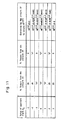
- the first divisor's multiple selection circuit 33 is for selectively outputting the double of the divisor D and 0 as a value A in response to the selection command from the circuit 23 in accordance with Fig. 11.
- the second divisor's multiple selection circuit 34 is for selectively outputting the divisor D and 0 as a value B in response to the selection command from the circuit 23 in accordance with Fig. 11.
- the quadruple of the partial remainder R (j) will be referred to as 4xR (j) , hereinafter.
- the addition/subtraction circuit 37 having three inputs for generating a subsequent partial remainder is to subtract the divisor D from the dividend R (0) , both normalized by a normalization circuit (not shown), and output the subtraction result as a first partial remainder R (2) on the initial stage of the division.
- the circuit 37 is then to execute the operation shown in Fig. 11 using A, B and 4xR (j) , in response to the addition/subtraction command from the circuit 23. More precisely, if the quotient digit q j is positive, A-B is subtracted from 4xR (j) ; and if the quotient digit q j is negative, A+B is added to 4xR (j) .
- A+B and A-B are each the product of the absolute value of the quotient digit q j and the divisor D.
- the addition/subtraction circuit 37 comprises a minuend bit inversion circuit 371, a 3-input addition circuit 372, and a sum bit inversion circuit 373.
- the circuits 371 and 373 each comprise a plurality of XOR gates 374, which are controlled to execute 4xR (j) +A+B or 4xR (j) -A-B by a control unit (not shown).
- the above circuits forming the divider unit 200 each comprise known AND, OR and NOT circuits for executing logical operations and so on shown in Figs. 5, 7 and 11.
- the divider unit 200 comprises other circuits including one for temporarily storing the partial remainder R (j) and one for counting the loops. Such circuits will not be described here because these circuits are not directly related to the gist of the present invention.
- the divider unit 200 having the above construction executes the division in the following way.
- the addition/subtraction circuit 37 subtracts the divisor D from the dividend R (0) and outputs the first partial remainder R (2) .
- the quotient digit selection circuit 23 outputs the value 1 as the quotient digit q0 (the value at ones place in the binary representation) and stores the above value 1 in the positive quotient digit storage circuit 24.
- the partial remainder interval selection circuit 22 decodes r0 (2) through r3 (2) in accordance with Fig. 5, and then selects the interval which the divisor D belongs to. Since the partial remainder R (2) is expressed in the two's complement representation, there is no need for conversion from the redundant binary representation into the two's complement representation.
- the quotient digit selection circuit 23 selects one of the values -3, -2, -1, 0, 1, 2 and 3 as a quotient digit q2 based on the selection result of the circuit 22 and d2 in accordance with Fig. 7.
- the positive quotient digit storage circuit 24 On receiving the quotient digit q2 from the circuit 23, the positive quotient digit storage circuit 24 stores the absolute value of the quotient digit q2 at a digit position in the circuit 24 if the quotient digit q2 is positive, the digit position corresponding to a first loop. If q2 is not positive, the circuit 24 stores 0 at the same digit position.
- the negative quotient digit storage circuit 25 stores the absolute value of the quotient digit q2 at a digit position in the circuit 25 if the quotient digit q2 is negative, the digit position corresponding to the first loop. If the quotient digit q2 is not negative, the circuit 25 stores 0 at the same digit position.
- the first divisor's multiple selection circuit 33 selectively outputs the double of the divisor D and 0 as the value A in response to the selection command from the circuit 23 in accordance with Fig. 11.
- the second divisor's multiple selection circuit 34 selectively outputs the divisor D and 0 as the value B in response to the selection command from the circuit 23 in accordance with Fig. 11.
- the addition/subtraction circuit 37 executes the operation shown in Fig, 11 using A, B and 4xR (2) sent from the circuit 36, whereby outputting a second partial remainder R (4) . Then, the operation goes back to 2) for the next loop, wherein R (4) is used instead of R (2) .
- the quotient conversion circuit 26 subtracts the value stored in the circuit 25 from the value stored in the circuit 24 and converts the subtraction result into the two's complement representation. If the final remainder R (n+2) is negative, the circuit 26 subtracts a value 1 at the lowest bit of the above subtraction result in the two's complement representation, whereby the quotient Q n is obtained. If necessary, the circuit 26 also adds the divisor D to the final remainder R (n+2) when R (n+2) is negative.
- the divider unit 200 although the generation logic of the divisor's multiple is complicated, the addition/subtraction circuit 37 having three inputs contributes to keep the hardware quite compact and also to maintain short the time to generate the partial remainders. Moreover, the quotient digit selection logic is extremely simple. As a result, the divider unit 200 executes the operation of each loop in a shorter period of time than the other units employing the algorithms proposed by D.E. Atkins with approximately the same level of hardware.
- the divider unit 200 is applied to an apparatus equipped with a 3-input adding unit such as a unit for calculating the number of floating-point numbers, the 3-input adding unit may also be used as the circuit 372. In such case, the hardware can still be more compact. If the divider unit 200 is applied to an apparatus equipped with a 2-input adding unit, the hardware of the 2-input adding unit may be extended a little to be a 3-input unit.
- a divider unit 400 will be described in which a partial remainder R (j) , as well as a quotient digit q j , is expressed in the redundant binary representation in the radix-8 scheme.
- the divider unit 400 employs the following algorithm, in which the value at the i'th binary place of the partial remainder R (j) is referred to as r i (j) in the two's complement representation.
- Figs. 12 and 13 show a partial remainder interval selection logic as mentioned in Embodiment I, concerning the partial remainder R (j) expressed in the two's complement representation.
- Fig. 14 shows a range of the divisor D in each partial remainder interval.
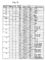
- Figs. 15 and 16 show a divisor interval selection logic as mentioned in Embodiment I. Same definitions are applied to Figs. 12 through 16 as to Figs. 5 through 7.
- each range of the divisor D includes both the D min. and D max. values concerning the theoretical borders. Concerning the borders applicable in this embodiment, each range includes the D min. value but excludes the D max. value.
- the divider unit 400 for executing the division using the above algorithm will be described referring to Figs. 17 through 24.
- Fig. 17 is a block diagram of the divider unit 400.
- divisor interval selection circuit 41 refers to a divisor interval selection circuit for selecting one interval which the divisor D belongs to out of a plurality of intervals bordered by specified values, the selection being done based d2 through d6 in accordance with Figs. 15 and 16.
- R0 (j) is a sign of the partial remainder R (j)
- r1 (j) through r5 (j) are values at the first to the fifth binary places of the partial remainder R (j) .
- the circuit 43 refers to a quotient digit selection circuit for selecting one value as the quotient digit q j out of values -7, -6, -5, -4, -3, -2, -1, 0, 1, 2, 3, 4, 5, 6 and 7, of which absolute values are each represented in three bits. The selection is done based on the selection result of the circuits 41 and 42 in accordance with Figs. 15 and 16.
- the circuit 43 is to output a value 1 as a quotient digit q0 on an initial stage of the division.
- the circuit 43 is also to send a selection command and an addition/subtraction command to first and second divisor's multiple selection circuits 53 and 54 (will be described later in detail) and the circuit 57.
- 50, 51 and 52 refer to divisor's double, quadruple and octuple generation circuits for generating the double, the quadruple and the octuple of the divisor D, respectively.
- the double, the quadruple and the octuple of the divisor D will be referred to 2xD, 4xD and 8xD respectively hereinafter.
- the first divisor's multiple selection circuit 53 is for selectively outputting the quadruple and the octuple of the divisor D and 0 as a value A in response to the selection command from the circuit 43 in accordance with Fig. 18.
- the second divisor's multiple selection circuit 54 is for selectively outputting the double of the divisor D, the divisor D and 0 as a value B in response to the selection command from the circuit 43 in accordance with Fig. 18.
- the circuit 55 refers to a first addition/subtraction circuit having two inputs for generating a divisor's multiple.
- the circuit 55 is to execute the operation shown in Fig. 18 using the values A and B in response to the addition/subtraction command from the circuit 43, whereby to generate a product C (A+B or A-B) of the absolute value of the quotient digit q j and the divisor D.
- the product C is expressed in the redundant binary representation.
- the product C may be generated loop by loop, or a plurality of possible products may be generated in advance. In the latter case, when the value of the quotient digit q j is determined, one of the products is selected.
- + indicates either addition or subtraction is acceptable.
- the first addition/subtraction circuit 55 has a construction shown in Fig. 19.
- 551i refers to a first addition cell for operating values a i and b i at the i'th digit of the values A and B in accordance with Fig. 20, whereby to output an intermediate carry and an intermediate sum.
- Fig. 20 the value to the left of ",” is the intermediate carry and the value to the right thereof is the intermediate sum.
- 552i refers to a second addition cell for operating the intermediate sum outputted by the first addition cell 551 i and the intermediate carry outputted by the first addition cell 551 i-1 in accordance with Fig. 21 and outputting the operation result as a value c i in the redundant binary representation.
- the value in each box indicates the value of c i ; and " ⁇ " indicates the combination of the intermediate carry and the intermediate sum is impossible.
- the circuit 55 executes addition and subtraction using positive binaries in the redundant binary scheme. Accordingly, the operation rules can be simple, which simplifies the construction of the circuit 55. Since carry and borrow are propagated to the upper digit only by one, the operation time does not depend on the bit length of the divisor D and so is shortened.
- the second addition/subtraction circuit 57 having two inputs for generating a subsequent partial remainder is to subtract the divisor D from the dividend R (0) , both normalized by a normalization circuit (not shown), and output the subtraction result as a first partial remainder R (3) on the initial stage of the division.
- the circuit 57 is then to execute the operation shown in Fig. 18 using the product C and 8xR (j) in response to the addition/subtraction command from the circuit 43. More precisely, if the quotient digit q j is positive, the product C is subtracted from 8xR (j) ; and if the quotient digit q j is negative, the product C is added to 8xR (j) .
- the second addition/subtraction circuit 57 has a construction shown in Fig. 22.
- 571i refers to a first addition cell for operating values c i and r i-3 at the i'th digit of the product C and of 8xR (j) in accordance with Fig. 23. whereby to output an intermediate carry and an intermediate sum.
- the value to the left of ",” is the intermediate carry and the value to the right thereof is the intermediate sum.
- 572i refers to a second addition cell for operating the intermediate sum outputted by the first addition cell 571 i and the intermediate carry outputted by the first addition cell 571 i-1 in accordance with Fig. 24 with the same operation rules of Fig. 21 and outputting the operation result as the partial remainder R (j+3) in the redundant binary representation.
- the circuit 57 executes addition and subtraction using positive and negative binaries in the redundant binary scheme. However, since carry and borrow are propagated to the upper digit only by two, the operation time does not depend on the bit length of the divisor D and so is shortened.
- the divider unit 400 having the above construction executes the division in the following way.
- the second addition/subtraction circuit 57 subtracts the divisor D from the dividend R (0) and outputs the first partial remainder R (3) .
- the quotient digit selection circuit 43 outputs the value 1 as the quotient digit q0 (the value at ones place in the binary representation) and stores the above value 1 in the positive quotient digit storage circuit 44.
- the divisor interval selection circuit 41 decodes d2 through d6 in accordance with Figs. 15 and 16, whereby to select the interval which the divisor D belongs to. Such selection is done only once on the initial stage of the division, and the result is retained until the division is finished.
- d2 through d6 are values at the second through the sixth binary places of the divisor D.
- the partial remainder interval selection circuit 42 converts the upper five digits of the partial remainder R (3) into the two' complement representation and decodes r1 (3) through r5 (3) in accordance with Figs. 12 and 13, and then selects the interval which the partial remainder R (3) belongs to.
- the quotient digit selection circuit 43 selects one of the values -7, -6, -5, -4, -3, -2, -1, 0, 1, 2, 3, 4, 5, 6 and 7 as a quotient digit q3 based on the selection results of the circuit 41 and 42 in accordance with Figs. 15 and 16.
- the positive quotient digit storage circuit 44 On receiving the quotient digit q3 from the circuit 43, the positive quotient digit storage circuit 44 stores the absolute value of the quotient digit q3 at a digit position in the circuit 44 if the quotient digit q3 is positive, the digit position corresponding to a first loop. If q3 is not positive, the circuit 44 stores 0 at the same digit position.
- the negative quotient digit storage circuit 45 stores the absolute value of q3 at a digit position in the circuit 45 if q3 is negative, the digit position corresponding to the first loop. If the quotient digit q j is not negative, the circuit 45 stores 0 at the same digit position.
- the first divisor's multiple selection circuit 53 selectively outputs the octuple and the quadruple of the divisor D and 0 as a value A in response to the selection command from the circuit 43 in accordance with Fig. 18.
- the second divisor's multiple selection circuit 54 selectively outputs the double of the divisor D, the divisor D and 0 as a value B in response to the selection command from the circuit 43 in accordance with Fig. 18.
- the first addition/subtraction circuit 55 executes the operation shown in Fig. 18 using A and B, whereby outputting the product C of the absolute value of the quotient digit q3 and the divisor D.
- the second addition/subtraction circuit 57 executes the operation shown in Fig. 18 using the product C and 8xR (j) , whereby outputting a second partial remainder R (6) . Then, the operation goes back to 2) for thee next loop, wherein R (6) is used instead of R (3) .
- the quotient conversation circuit 46 subtracts the value stored in the curcuit 45 from the value stored in the circuit 44 and converts the subtraction result into the two's complement representation. If the final remainder R (n+3) is negative, the circuit 46 subtracts a value 1 at the lowest bit of the above subtraction result in the two's complement representation, whereby the quotient Q n is obtained. If necessary, the circuit 46 converts the final remainder R (n+3) into the two's complement representation in the same manner by a final remainder compensation circuit (not shown). If necessary, the circuit 46 also adds the divisor D to the final remainder R (n+3) when R (n+3) is negative.
- the quotient digit selection logic is extremely simple. Accordingly, the radix-8 scheme is employed while keeping the hardware compact, and also the times the operation of the loop is repeated can be reduced to 1/3 of the conventional divider units designed for the radix-2 SRT division and the nonrestoring division.
- the partial remainder is obtained through two-step addition/subtraction by the circuits 55 and 57.
- the time delay is small enough to realize a high-speed operation.
- a divider unit 600 will be described in which a partial remainder R (j) is expressed in the two's complement representation in the radix-8 scheme.
- Fig. 25 shows a block diagram of the divider unit 600.
- 64 and 65 are positive and negative quotient digit storage circuits, respectively.
- 66 is a quotient conversion circuit.
- 70, 71 and 72 are divisor's double, quadruple and octuple generation circuits, respectively.
- 73 and 74 are first and second divisor's multiple selection circuits, respectively.
- 76 is a partial remainder's octuple generation circuit.
- the circuits 64, 65, 66, 70, 71, 72, 73, 74 and 76 correspond to counterparts thereof of Embodiment II and will not be described in Embodiment III.
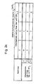
- each range of the divisor D excludes the D min. and the D max. values concerning the theoretical borders. Concerning the borders applicable to this embodiment, each range includes the D min. value but excludes the D max. value.
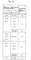
- 62 refers to a partial remainder selection circuit for selecting one interval which the partial remainder R (j) belongs to in the same manner as the circuit 22 of Embodiment I in accordance with Fig. 26.
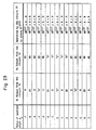
- 63 refers to a quotient digit selection circuit for selecting one of values -7, -6, -5, -4, -3, -2, -1, 0, 1, 2, 3, 4, 5, 6 and 7 as a quotient digit q j in the same manner as the circuit 43 of Embodiment II in accordance with Fig. 28.
- circuits 73 and 74 and an addition/subtraction circuit 77 having three inputs for generating a subsequent partial remainder are for executing the operation shown in Figs. 29, whereby to execute addition or subtraction using 8xR (j) , A and B.
- the division is executed with the same algorithm as that of Embodiment II. Owing to the radix-8 scheme used in this unit, the times the operation of the loop is repeated is reduced as in Embodiment II. Moreover, the time required for the quotient digit selection is shorter than in Embodiment II despite of the radix of 8. As a result, the division processing speed is remarkably enhanced.
- the dividend and the divisor are normalized in the range of 1/2 or more but less than 1.
- the normalization number can be set as 2 k ⁇ 1 ⁇ normalization number ⁇ 2 k , where k is an arbitrary integer. If 1 ⁇ normalization number ⁇ 2, for instance, the position of the binary point in the case of 1/2 ⁇ normalization number ⁇ 1 is shifted to the lower bit or digit by one. In such case, the bit position described in the above embodiments appears to be shifted to the upper bit or digit by one. In other words, multiplying the dividend and the divisor by the same value leads to the same quotient. That is why the position of the binary point and the value of k are not essential in the above division procedure.
- integer division can be executed by adding a circuit for normalizing the divisor and a circuit for adjusting digits to the divider unit according to this invention.
- a value 1 may be outputted as a first quotient digit q 0 while outputting the dividend as a first partial remainder.
Landscapes
- Physics & Mathematics (AREA)
- General Physics & Mathematics (AREA)
- Engineering & Computer Science (AREA)
- Computational Mathematics (AREA)
- Mathematical Analysis (AREA)
- Mathematical Optimization (AREA)
- Pure & Applied Mathematics (AREA)
- Theoretical Computer Science (AREA)
- Computing Systems (AREA)
- General Engineering & Computer Science (AREA)
- Executing Machine-Instructions (AREA)
Applications Claiming Priority (4)
| Application Number | Priority Date | Filing Date | Title |
|---|---|---|---|
| JP95759/90 | 1990-04-10 | ||
| JP9575990 | 1990-04-10 | ||
| JP71405/91 | 1991-04-04 | ||
| JP3071405A JP2857505B2 (ja) | 1990-04-10 | 1991-04-04 | 除算装置 |
Publications (2)
| Publication Number | Publication Date |
|---|---|
| EP0452099A2 true EP0452099A2 (fr) | 1991-10-16 |
| EP0452099A3 EP0452099A3 (en) | 1993-06-09 |
Family
ID=26412506
Family Applications (1)
| Application Number | Title | Priority Date | Filing Date |
|---|---|---|---|
| EP19910303132 Withdrawn EP0452099A3 (en) | 1990-04-10 | 1991-04-09 | Divider unit |
Country Status (3)
| Country | Link |
|---|---|
| US (1) | US5206827A (fr) |
| EP (1) | EP0452099A3 (fr) |
| JP (1) | JP2857505B2 (fr) |
Cited By (1)
| Publication number | Priority date | Publication date | Assignee | Title |
|---|---|---|---|---|
| DE102013222842A1 (de) | 2013-11-11 | 2015-05-13 | Schaeffler Technologies Gmbh & Co. Kg | Stirnraddifferenzial mit Sinterplanetenträger |
Families Citing this family (7)
| Publication number | Priority date | Publication date | Assignee | Title |
|---|---|---|---|---|
| US5696713A (en) * | 1995-08-21 | 1997-12-09 | International Business Machines Corporation | Method for faster division by known divisor while maintaining desired accuracy |
| JP3604518B2 (ja) * | 1996-11-01 | 2004-12-22 | 株式会社ルネサステクノロジ | 除算装置 |
| US6233593B1 (en) * | 1998-11-18 | 2001-05-15 | Tektronix, Inc. | Fir filter based upon squaring |
| JP2000347836A (ja) * | 1999-06-04 | 2000-12-15 | Sony Corp | 高次基数除算器およびその方法 |
| US6748411B1 (en) | 2000-11-20 | 2004-06-08 | Agere Systems Inc. | Hierarchical carry-select multiple-input split adder |
| JP2004326112A (ja) * | 2003-04-25 | 2004-11-18 | Samsung Electronics Co Ltd | マルチプルモジュラス選択器、累算器、モンゴメリー掛け算器、マルチプルモジュラス発生方法、部分掛け発生方法、累算方法、掛け算方法、モジュラス選択器、およびブースレコーダ |
| JP7119543B2 (ja) | 2018-05-01 | 2022-08-17 | 富士通株式会社 | 加減算回路および加減算回路の制御方法 |
Family Cites Families (4)
| Publication number | Priority date | Publication date | Assignee | Title |
|---|---|---|---|---|
| US3733477A (en) * | 1972-02-04 | 1973-05-15 | Control Data Corp | Iterative binary divider utilizing multiples of the divisor |
| US3852581A (en) * | 1972-12-14 | 1974-12-03 | Burroughs Corp | Two bit binary divider |
| FR2301869A1 (fr) * | 1975-02-19 | 1976-09-17 | Szamitastech Koord | Procede et couplage rapide pour la division des nombres binaires |
| CA1231455A (fr) * | 1984-04-09 | 1988-01-12 | Masayuki Ikeda | Diviseur non retablisseur |
-
1991
- 1991-04-04 JP JP3071405A patent/JP2857505B2/ja not_active Expired - Fee Related
- 1991-04-09 EP EP19910303132 patent/EP0452099A3/en not_active Withdrawn
- 1991-04-09 US US07/682,902 patent/US5206827A/en not_active Expired - Fee Related
Cited By (1)
| Publication number | Priority date | Publication date | Assignee | Title |
|---|---|---|---|---|
| DE102013222842A1 (de) | 2013-11-11 | 2015-05-13 | Schaeffler Technologies Gmbh & Co. Kg | Stirnraddifferenzial mit Sinterplanetenträger |
Also Published As
| Publication number | Publication date |
|---|---|
| JPH04218831A (ja) | 1992-08-10 |
| JP2857505B2 (ja) | 1999-02-17 |
| US5206827A (en) | 1993-04-27 |
| EP0452099A3 (en) | 1993-06-09 |
Similar Documents
| Publication | Publication Date | Title |
|---|---|---|
| EP0149248B1 (fr) | Méthode et dispositif à division utilisant une approximation à interpolation | |
| JP3144816B2 (ja) | 除算を行なう装置 | |
| JP2622896B2 (ja) | 除算装置 | |
| US5696712A (en) | Three overlapped stages of radix-2 square root/division with speculative execution | |
| US5105378A (en) | High-radix divider | |
| US5132925A (en) | Radix-16 divider using overlapped quotient bit selection and concurrent quotient rounding and correction | |
| US5023827A (en) | Radix-16 divider using overlapped quotient bit selection and concurrent quotient rounding and correction | |
| US5184318A (en) | Rectangular array signed digit multiplier | |
| US20080208945A1 (en) | Method to compute an approximation to the reciprocal of the square root of a floating point number in ieee format | |
| EP0158530A2 (fr) | Diviseur non-restituant | |
| JP2001524698A (ja) | マルチプレシジョン整数演算用の装置 | |
| JPH07168697A (ja) | 倍精度除算回路および方法 | |
| US5784307A (en) | Division algorithm for floating point or integer numbers | |
| US5623435A (en) | Arithmetic unit capable of performing concurrent operations for high speed operation | |
| US5282156A (en) | Leading one anticipator and floating point addition/subtraction apparatus employing same | |
| US5206827A (en) | Iterative high radix divider decoding the upper bits of a divisor and dividend | |
| US5818745A (en) | Computer for performing non-restoring division | |
| KR970006408B1 (ko) | 논리회로의 자동설계방법 및 그 장치와 승산기 | |
| US7016930B2 (en) | Apparatus and method for performing operations implemented by iterative execution of a recurrence equation | |
| JP2511527B2 (ja) | 浮動小数点演算器 | |
| US6109777A (en) | Division with limited carry-propagation in quotient accumulation | |
| US5825681A (en) | Divider/multiplier circuit having high precision mode | |
| KR100329914B1 (ko) | 제산장치 | |
| RU2276805C2 (ru) | Способ и устройство для выделения целой и дробных компонент из данных с плавающей точкой | |
| JP3638218B2 (ja) | シフト機能付きalu命令を持つマイクロプロセッサ |
Legal Events
| Date | Code | Title | Description |
|---|---|---|---|
| PUAI | Public reference made under article 153(3) epc to a published international application that has entered the european phase |
Free format text: ORIGINAL CODE: 0009012 |
|
| AK | Designated contracting states |
Kind code of ref document: A2 Designated state(s): DE FR GB NL |
|
| PUAL | Search report despatched |
Free format text: ORIGINAL CODE: 0009013 |
|
| AK | Designated contracting states |
Kind code of ref document: A3 Designated state(s): DE FR GB NL |
|
| 17P | Request for examination filed |
Effective date: 19931201 |
|
| 17Q | First examination report despatched |
Effective date: 19960703 |
|
| STAA | Information on the status of an ep patent application or granted ep patent |
Free format text: STATUS: THE APPLICATION IS DEEMED TO BE WITHDRAWN |
|
| 18D | Application deemed to be withdrawn |
Effective date: 19961114 |