EP0452109A1 - Méthode et appareil pour contrôler l'écoulement de l'air de refroidissement pour des extrémités des aubes de turbines - Google Patents
Méthode et appareil pour contrôler l'écoulement de l'air de refroidissement pour des extrémités des aubes de turbines Download PDFInfo
- Publication number
- EP0452109A1 EP0452109A1 EP91303158A EP91303158A EP0452109A1 EP 0452109 A1 EP0452109 A1 EP 0452109A1 EP 91303158 A EP91303158 A EP 91303158A EP 91303158 A EP91303158 A EP 91303158A EP 0452109 A1 EP0452109 A1 EP 0452109A1
- Authority
- EP
- European Patent Office
- Prior art keywords
- blade
- channel
- turbomachinery
- pin
- passages
- Prior art date
- Legal status (The legal status is an assumption and is not a legal conclusion. Google has not performed a legal analysis and makes no representation as to the accuracy of the status listed.)
- Withdrawn
Links
- 238000001816 cooling Methods 0.000 title claims abstract description 27
- 238000000034 method Methods 0.000 title claims abstract description 11
- 239000012809 cooling fluid Substances 0.000 claims abstract description 7
- 239000000463 material Substances 0.000 claims description 4
- 230000003647 oxidation Effects 0.000 claims description 2
- 238000007254 oxidation reaction Methods 0.000 claims description 2
- 239000012530 fluid Substances 0.000 claims 4
- 239000002826 coolant Substances 0.000 claims 2
- 239000007789 gas Substances 0.000 description 6
- 239000000919 ceramic Substances 0.000 description 2
- 238000012986 modification Methods 0.000 description 2
- 230000004048 modification Effects 0.000 description 2
- 230000004075 alteration Effects 0.000 description 1
- 238000005266 casting Methods 0.000 description 1
- 210000003041 ligament Anatomy 0.000 description 1
- 238000004519 manufacturing process Methods 0.000 description 1
- 239000002184 metal Substances 0.000 description 1
- 230000035882 stress Effects 0.000 description 1
- 230000008646 thermal stress Effects 0.000 description 1
Images
Classifications
-
- F—MECHANICAL ENGINEERING; LIGHTING; HEATING; WEAPONS; BLASTING
- F01—MACHINES OR ENGINES IN GENERAL; ENGINE PLANTS IN GENERAL; STEAM ENGINES
- F01D—NON-POSITIVE DISPLACEMENT MACHINES OR ENGINES, e.g. STEAM TURBINES
- F01D5/00—Blades; Blade-carrying members; Heating, heat-insulating, cooling or antivibration means on the blades or the members
- F01D5/12—Blades
- F01D5/14—Form or construction
- F01D5/18—Hollow blades, i.e. blades with cooling or heating channels or cavities; Heating, heat-insulating or cooling means on blades
- F01D5/187—Convection cooling
-
- F—MECHANICAL ENGINEERING; LIGHTING; HEATING; WEAPONS; BLASTING
- F02—COMBUSTION ENGINES; HOT-GAS OR COMBUSTION-PRODUCT ENGINE PLANTS
- F02C—GAS-TURBINE PLANTS; AIR INTAKES FOR JET-PROPULSION PLANTS; CONTROLLING FUEL SUPPLY IN AIR-BREATHING JET-PROPULSION PLANTS
- F02C7/00—Features, components parts, details or accessories, not provided for in, or of interest apart form groups F02C1/00 - F02C6/00; Air intakes for jet-propulsion plants
- F02C7/04—Air intakes for gas-turbine plants or jet-propulsion plants
-
- F—MECHANICAL ENGINEERING; LIGHTING; HEATING; WEAPONS; BLASTING
- F01—MACHINES OR ENGINES IN GENERAL; ENGINE PLANTS IN GENERAL; STEAM ENGINES
- F01D—NON-POSITIVE DISPLACEMENT MACHINES OR ENGINES, e.g. STEAM TURBINES
- F01D5/00—Blades; Blade-carrying members; Heating, heat-insulating, cooling or antivibration means on the blades or the members
- F01D5/12—Blades
- F01D5/14—Form or construction
- F01D5/18—Hollow blades, i.e. blades with cooling or heating channels or cavities; Heating, heat-insulating or cooling means on blades
-
- Y—GENERAL TAGGING OF NEW TECHNOLOGICAL DEVELOPMENTS; GENERAL TAGGING OF CROSS-SECTIONAL TECHNOLOGIES SPANNING OVER SEVERAL SECTIONS OF THE IPC; TECHNICAL SUBJECTS COVERED BY FORMER USPC CROSS-REFERENCE ART COLLECTIONS [XRACs] AND DIGESTS
- Y02—TECHNOLOGIES OR APPLICATIONS FOR MITIGATION OR ADAPTATION AGAINST CLIMATE CHANGE
- Y02T—CLIMATE CHANGE MITIGATION TECHNOLOGIES RELATED TO TRANSPORTATION
- Y02T50/00—Aeronautics or air transport
- Y02T50/60—Efficient propulsion technologies, e.g. for aircraft
Definitions
- This invention relates in general to turbo-machinery blades and, more particularly, to an improved apparatus and method for cooling the orifice air flow at gas turbine bucket trailing edge tips.
- a turbine operated by burning gases drives a compressor which furnishes air to a combustor.
- Such turbine engines operate at relatively high temperatures.
- the capacity of such an engine is limited to a large extent by the ability of the material from which the turbine blades (sometimes referred to herein as "buckets") are made to withstand thermal stresses which develop at such relatively high operating temperatures.
- the problem may be particularly severe in an industrial gas turbine engine because of the relatively large size of certain engine parts, such as the turbine blades.
- hollow, convectively-cooled turbine blades are frequently utilized.
- Such blades generally have interior passageways which provide flow passages to ensure efficient cooling whereby all the portions of the blades may be maintained at relatively uniform temperature.
- U.S. Patent No. 4,236,870 to Hucul, Jr., et al discloses one method of governing the magnitude of cooling air flow through the turbine blade which permits future modification of the blade cooling system without expensive alteration or blade redesign.
- the Hucul, Jr., et al patent utilizes a metering plate located at the base of the blade containing one or more metering orifices which communicate with the internal cooling passageways of the blade.
- replacing the metering plate to vary cooling air flow necessarily requires removal of the entire blade, and replacement of the metering plate changes the cooling characteristics throughout the entire blade, not just the tip.
- each turbomachinery blade contains at least one radial cooling passage connecting a hollow blade interior cavity with the outside of the blade.
- a transversely-oriented elongate channel connects at least one of the cooling passages with the trailing edge of the blade.
- a pin Secured within the transversely-oriented channel is a pin which extends far enough into at least one of the radial cooling passages to partially obstruct the cooling fluid flow depending on the needs of the design.
- a second intersecting hole is drilled from the bucket tip to the transversely-oriented channel and a punch is brought down through the intersecting hole to slightly deform the pin, staking it in place.
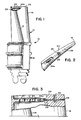
- a bucket 10 for an industrial gas turbine engine includes a base portion or root 12 adapted for connection to a rotatable hub (not shown), and a blade portion 14.
- the blade is typically airfoil-shaped, having a leading edge 16 and trailing edge 18.
- Blade portion 14 can contain any number of arrangements of internal cooling fluid passages forming an internal cavity 20, as shown partially in the cut-away portion of FIGURE 1, with air being utilized as the cooling fluid in the preferred exemplary embodiment.
- the internal cooling air passageway arrangement forming cavity 20 is connected to the tip 22 of the blade portion 14 by a plurality of tip exit holes 24 as shown in FIGURES 1 and 3. In the preferred exemplary embodiment, there are five exit holes 24 and the metering method and system of the present invention is applied to the trailing edge tip exit hole 24a.
- a channel 26 is drilled transversely from the trailing edge 18 and intersects with the trailing edge tip exit hole 24a.
- channel 26 is oriented perpendicular, or transverse, to exit hole 24a.
- An elongate pin 28 is inserted into channel 26 and extends into the trailing edge tip exit hole 24a.
- channel 26 can be extended further into other tip exit holes 24, and the invention is not limited to intersection solely with the trailing edge tip exit hole 24a.
- the length of pin 28 can be varied, as can its location within channel 26 to meter the amount of air flowing out of the trailing edge tip exit hole 24a.
- a radially-oriented hole 30 is drilled from the tip 22 of blade portion 14 radially inward so that it intersects channel 26 at a point between trailing edge tip exit hole 24a and the trailing edge 18, as shown in FIGURES 2 and 3.
- a punch can be brought down into the intersecting hole 30 to slightly deform pin 28 to prevent it from moving longitudinally within channel 26, thus staking it in place.
- pin 28 is constructed of a ductile, oxidation-resistant material with a diameter of about .045 inches (1.1 mm). Other suitable material may also be employed.
Landscapes
- Engineering & Computer Science (AREA)
- Mechanical Engineering (AREA)
- General Engineering & Computer Science (AREA)
- Chemical & Material Sciences (AREA)
- Combustion & Propulsion (AREA)
- Turbine Rotor Nozzle Sealing (AREA)
Applications Claiming Priority (2)
| Application Number | Priority Date | Filing Date | Title |
|---|---|---|---|
| US521891 | 1990-04-13 | ||
| US07/521,891 US5125798A (en) | 1990-04-13 | 1990-04-13 | Method and apparatus for cooling air flow at gas turbine bucket trailing edge tip |
Publications (1)
| Publication Number | Publication Date |
|---|---|
| EP0452109A1 true EP0452109A1 (fr) | 1991-10-16 |
Family
ID=24078577
Family Applications (1)
| Application Number | Title | Priority Date | Filing Date |
|---|---|---|---|
| EP91303158A Withdrawn EP0452109A1 (fr) | 1990-04-13 | 1991-04-10 | Méthode et appareil pour contrôler l'écoulement de l'air de refroidissement pour des extrémités des aubes de turbines |
Country Status (6)
| Country | Link |
|---|---|
| US (1) | US5125798A (fr) |
| EP (1) | EP0452109A1 (fr) |
| JP (1) | JPH04252805A (fr) |
| KR (1) | KR940001324B1 (fr) |
| CN (1) | CN1055574A (fr) |
| NO (1) | NO911450L (fr) |
Cited By (1)
| Publication number | Priority date | Publication date | Assignee | Title |
|---|---|---|---|---|
| EP0768448A1 (fr) * | 1995-10-10 | 1997-04-16 | United Technologies Electro Systems, Inc. | Aubes statoriques réfrigerées pour turbines |
Families Citing this family (17)
| Publication number | Priority date | Publication date | Assignee | Title |
|---|---|---|---|---|
| US5511946A (en) * | 1994-12-08 | 1996-04-30 | General Electric Company | Cooled airfoil tip corner |
| US5842829A (en) | 1996-09-26 | 1998-12-01 | General Electric Co. | Cooling circuits for trailing edge cavities in airfoils |
| US5902093A (en) * | 1997-08-22 | 1999-05-11 | General Electric Company | Crack arresting rotor blade |
| US5927946A (en) * | 1997-09-29 | 1999-07-27 | General Electric Company | Turbine blade having recuperative trailing edge tip cooling |
| US7001144B2 (en) * | 2003-02-27 | 2006-02-21 | General Electric Company | Gas turbine and method for reducing bucket tip shroud creep rate |
| US7097419B2 (en) | 2004-07-26 | 2006-08-29 | General Electric Company | Common tip chamber blade |
| US7278826B2 (en) * | 2004-08-18 | 2007-10-09 | Pratt & Whitney Canada Corp. | Airfoil cooling passage trailing edge flow restriction |
| US7300250B2 (en) * | 2005-09-28 | 2007-11-27 | Pratt & Whitney Canada Corp. | Cooled airfoil trailing edge tip exit |
| US7695243B2 (en) | 2006-07-27 | 2010-04-13 | General Electric Company | Dust hole dome blade |
| US8016562B2 (en) * | 2007-11-20 | 2011-09-13 | Siemens Energy, Inc. | Turbine blade tip cooling system |
| US8157504B2 (en) * | 2009-04-17 | 2012-04-17 | General Electric Company | Rotor blades for turbine engines |
| US9464536B2 (en) | 2012-10-18 | 2016-10-11 | General Electric Company | Sealing arrangement for a turbine system and method of sealing between two turbine components |
| US10107108B2 (en) | 2015-04-29 | 2018-10-23 | General Electric Company | Rotor blade having a flared tip |
| US10774658B2 (en) | 2017-07-28 | 2020-09-15 | General Electric Company | Interior cooling configurations in turbine blades and methods of manufacture relating thereto |
| US10563519B2 (en) | 2018-02-19 | 2020-02-18 | General Electric Company | Engine component with cooling hole |
| US10975704B2 (en) | 2018-02-19 | 2021-04-13 | General Electric Company | Engine component with cooling hole |
| CN114151148B (zh) * | 2021-12-08 | 2024-02-23 | 上海电气集团股份有限公司 | 叶栅气膜冷却试验的测量修正方法、装置、设备及介质 |
Citations (5)
| Publication number | Priority date | Publication date | Assignee | Title |
|---|---|---|---|---|
| US3393894A (en) * | 1965-12-28 | 1968-07-23 | Rolls Royce | Blade assembly |
| US4073599A (en) * | 1976-08-26 | 1978-02-14 | Westinghouse Electric Corporation | Hollow turbine blade tip closure |
| FR2389759A1 (fr) * | 1977-05-05 | 1978-12-01 | Rolls Royce | |
| GB2067674A (en) * | 1980-01-23 | 1981-07-30 | Rolls Royce | Rotor blade for a gas turbine engine |
| GB2077363A (en) * | 1980-06-05 | 1981-12-16 | United Technologies Corp | Wafer tip cap for rotor blades |
Family Cites Families (15)
| Publication number | Priority date | Publication date | Assignee | Title |
|---|---|---|---|---|
| US2750147A (en) * | 1947-10-28 | 1956-06-12 | Power Jets Res & Dev Ltd | Blading for turbines and like machines |
| GB641146A (en) * | 1948-08-03 | 1950-08-02 | Power Jets Res & Dev Ltd | Improvements in turbine blades |
| US2763427A (en) * | 1949-10-13 | 1956-09-18 | Armstrong Siddeley Motors Ltd | Axial-flow machines |
| US2839268A (en) * | 1950-01-18 | 1958-06-17 | Allis Chalmers Mfg Co | Gas turbine |
| US2883151A (en) * | 1954-01-26 | 1959-04-21 | Curtiss Wright Corp | Turbine cooling system |
| BE795073A (fr) * | 1972-03-02 | 1973-05-29 | Gen Electric | Procede pour la fabrication d'aubes creuses |
| US3867068A (en) * | 1973-03-30 | 1975-02-18 | Gen Electric | Turbomachinery blade cooling insert retainers |
| US4236870A (en) * | 1977-12-27 | 1980-12-02 | United Technologies Corporation | Turbine blade |
| US4203706A (en) * | 1977-12-28 | 1980-05-20 | United Technologies Corporation | Radial wafer airfoil construction |
| FR2552817B1 (fr) * | 1978-11-27 | 1988-02-12 | Snecma | Perfectionnements au refroidissement des rotors de turbines |
| US4453888A (en) * | 1981-04-01 | 1984-06-12 | United Technologies Corporation | Nozzle for a coolable rotor blade |
| DE3306894A1 (de) * | 1983-02-26 | 1984-08-30 | MTU Motoren- und Turbinen-Union München GmbH, 8000 München | Turbinenleit- oder laufschaufel mit kuehlkanal |
| US4526512A (en) * | 1983-03-28 | 1985-07-02 | General Electric Co. | Cooling flow control device for turbine blades |
| JPS62228603A (ja) * | 1986-03-31 | 1987-10-07 | Toshiba Corp | ガスタ−ビンの翼 |
| DE3629910A1 (de) * | 1986-09-03 | 1988-03-17 | Mtu Muenchen Gmbh | Metallisches hohlbauteil mit einem metallischen einsatz, insbesondere turbinenschaufel mit kuehleinsatz |
-
1990
- 1990-04-13 US US07/521,891 patent/US5125798A/en not_active Expired - Fee Related
-
1991
- 1991-02-22 KR KR1019910002898A patent/KR940001324B1/ko not_active Expired - Lifetime
- 1991-04-04 JP JP3098006A patent/JPH04252805A/ja not_active Withdrawn
- 1991-04-10 CN CN91102268A patent/CN1055574A/zh active Pending
- 1991-04-10 EP EP91303158A patent/EP0452109A1/fr not_active Withdrawn
- 1991-04-12 NO NO91911450A patent/NO911450L/no unknown
Patent Citations (5)
| Publication number | Priority date | Publication date | Assignee | Title |
|---|---|---|---|---|
| US3393894A (en) * | 1965-12-28 | 1968-07-23 | Rolls Royce | Blade assembly |
| US4073599A (en) * | 1976-08-26 | 1978-02-14 | Westinghouse Electric Corporation | Hollow turbine blade tip closure |
| FR2389759A1 (fr) * | 1977-05-05 | 1978-12-01 | Rolls Royce | |
| GB2067674A (en) * | 1980-01-23 | 1981-07-30 | Rolls Royce | Rotor blade for a gas turbine engine |
| GB2077363A (en) * | 1980-06-05 | 1981-12-16 | United Technologies Corp | Wafer tip cap for rotor blades |
Cited By (1)
| Publication number | Priority date | Publication date | Assignee | Title |
|---|---|---|---|---|
| EP0768448A1 (fr) * | 1995-10-10 | 1997-04-16 | United Technologies Electro Systems, Inc. | Aubes statoriques réfrigerées pour turbines |
Also Published As
| Publication number | Publication date |
|---|---|
| US5125798A (en) | 1992-06-30 |
| JPH04252805A (ja) | 1992-09-08 |
| NO911450D0 (no) | 1991-04-12 |
| NO911450L (no) | 1991-10-14 |
| KR940001324B1 (ko) | 1994-02-19 |
| KR910018662A (ko) | 1991-11-30 |
| CN1055574A (zh) | 1991-10-23 |
Similar Documents
| Publication | Publication Date | Title |
|---|---|---|
| EP0452109A1 (fr) | Méthode et appareil pour contrôler l'écoulement de l'air de refroidissement pour des extrémités des aubes de turbines | |
| US5243759A (en) | Method of casting to control the cooling air flow rate of the airfoil trailing edge | |
| US6234753B1 (en) | Turbine airfoil with internal cooling | |
| US9863254B2 (en) | Turbine airfoil with local wall thickness control | |
| US7351036B2 (en) | Turbine airfoil cooling system with elbowed, diffusion film cooling hole | |
| US5927946A (en) | Turbine blade having recuperative trailing edge tip cooling | |
| US4168938A (en) | Blade or vane for a gas turbine engine | |
| US3973874A (en) | Impingement baffle collars | |
| US20050111978A1 (en) | Turbine blade airfoil having improved creep capability | |
| US20100024216A1 (en) | Rotor blade and method of fabricating the same | |
| EP0838575B1 (fr) | Méthode de refroidissement des aubes de stator | |
| EP3124743A1 (fr) | Aube de distributeur et procédé de fabrication d'une aube de distributeur | |
| US20190085705A1 (en) | Component for a turbine engine with a film-hole | |
| GB2290833A (en) | Turbine blade cooling | |
| US6884023B2 (en) | Integral swirl knife edge injection assembly | |
| EP3196414B1 (fr) | Extrémité d'aube à double alimentation | |
| EP1101898B1 (fr) | Aube de turbine à gaz | |
| EP3757352B1 (fr) | Procédé de fabrication d'un profil d'aube avec cavités internes | |
| JP2009103123A (ja) | タービン用の空冷式バケット | |
| KR102715377B1 (ko) | 에어포일에 대한 2개의 부분 냉각 통로 | |
| US6464462B2 (en) | Gas turbine bucket wall thickness control | |
| US7431561B2 (en) | Method and apparatus for cooling gas turbine rotor blades | |
| US6176678B1 (en) | Apparatus and methods for turbine blade cooling | |
| US12359569B2 (en) | Turbine blade tip cooling hole supply plenum | |
| US10760431B2 (en) | Component for a turbine engine with a cooling hole |
Legal Events
| Date | Code | Title | Description |
|---|---|---|---|
| PUAI | Public reference made under article 153(3) epc to a published international application that has entered the european phase |
Free format text: ORIGINAL CODE: 0009012 |
|
| AK | Designated contracting states |
Kind code of ref document: A1 Designated state(s): CH DE FR GB IT LI NL SE |
|
| 17P | Request for examination filed |
Effective date: 19911220 |
|
| STAA | Information on the status of an ep patent application or granted ep patent |
Free format text: STATUS: THE APPLICATION HAS BEEN WITHDRAWN |
|
| 18W | Application withdrawn |
Withdrawal date: 19930611 |