EP0452131B1 - Méthode et appareil de sortie - Google Patents
Méthode et appareil de sortie Download PDFInfo
- Publication number
- EP0452131B1 EP0452131B1 EP91303216A EP91303216A EP0452131B1 EP 0452131 B1 EP0452131 B1 EP 0452131B1 EP 91303216 A EP91303216 A EP 91303216A EP 91303216 A EP91303216 A EP 91303216A EP 0452131 B1 EP0452131 B1 EP 0452131B1
- Authority
- EP
- European Patent Office
- Prior art keywords
- image data
- resolution
- output resolution
- accordance
- storage means
- Prior art date
- Legal status (The legal status is an assumption and is not a legal conclusion. Google has not performed a legal analysis and makes no representation as to the accuracy of the status listed.)
- Expired - Lifetime
Links
Images


Classifications
-
- G—PHYSICS
- G06—COMPUTING OR CALCULATING; COUNTING
- G06K—GRAPHICAL DATA READING; PRESENTATION OF DATA; RECORD CARRIERS; HANDLING RECORD CARRIERS
- G06K15/00—Arrangements for producing a permanent visual presentation of the output data, e.g. computer output printers
- G06K15/02—Arrangements for producing a permanent visual presentation of the output data, e.g. computer output printers using printers
-
- G—PHYSICS
- G06—COMPUTING OR CALCULATING; COUNTING
- G06K—GRAPHICAL DATA READING; PRESENTATION OF DATA; RECORD CARRIERS; HANDLING RECORD CARRIERS
- G06K2215/00—Arrangements for producing a permanent visual presentation of the output data
- G06K2215/0002—Handling the output data
-
- G—PHYSICS
- G06—COMPUTING OR CALCULATING; COUNTING
- G06K—GRAPHICAL DATA READING; PRESENTATION OF DATA; RECORD CARRIERS; HANDLING RECORD CARRIERS
- G06K2215/00—Arrangements for producing a permanent visual presentation of the output data
- G06K2215/0002—Handling the output data
- G06K2215/002—Generic data access
- G06K2215/0037—Generic data access depending on an output condition, e.g. size, resolution
Definitions
- the present invention relates to an output method and apparatus allowing a variable resolution of output image data.
- LBPs Laser printers
- Some of laser printers has a resolution of 300 dpi (dot per inch) to 600 dpi or higher.
- bit image data is generated in accordance with code data supplied from a host computer or the like.
- bit image data is generated using a scalable font in place of a bit image font.
- a bit image font represents bit image data itself stored in a storage unit, whereas a scalable font has a variable font size such that character shape data is stored not as a bit image but as vector information, and the vector information is processed to obtain a bit image having a designated character size.
- the scalable font provides a smaller memory capacity and a better print quality of a magnified character than a bit map font which requires a memory capacity linearly increasing as the number of font sizes increases.
- German Patent Specification No. DE-A-3931128 discloses an output apparatus as set forth in the preamble of claim 1 in which the output resolution can be set in accordance with an identified storage capacity.
- this prior specification does not solve the problem of obtaining optimum resolution over different print areas.
- the print process system of an LBP will be given by way of example for the discussion of this invention.
- the print process system of an LBP itself is well known in the art, so the description thereof will be omitted.
- the invention is not limited only to the following embodiments, but applicable to an apparatus constructed of a single apparatus unit and a system constructed of a plurality of apparatus units.
- the present invention is also applicable to the apparatus or system supplied with programs executing the concept of this invention.
- Fig. 1 shows the relationship between a horizontal synchro signal (a beam detect signal, hereinafter called BD) of an LBP and a print area on a recording medium on which image data is formed.
- BD a beam detect signal
- a character t is a time required for a laser beam scanned by a polygon mirror to reach a print area after the falling edge timing of BD.
- X represents the length in the horizontal (main scan) direction of the print area
- Y represents the length in the vertical (sub scan) direction of the print area.
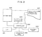
- Fig. 2 is a block diagram showing a recording apparatus according to an embodiment of this invention.
- an interface unit 201 receives data from a recording data source such as a host computer.
- a controller 202 controls the entire operation of the printing apparatus, analyzes command data supplied from I/F 201 to generate a bit image.
- a scalable font unit 203 stores, in the form of vector information, character image data corresponding to character code data sent from the data source.
- a calculator 204 calculates a print character bit image and an available resolution. The print character bit image is calculated from the vector information by means of interpolation for a predetermined curve such as a spline curve and a Bezier curve and by means of various algorithms.
- a bit map memory 205 stores bit image data to be printed.
- a resolution controller 206 executes physical control processes for attaining an objective resolution, such as controlling the rotation of a polygon mirror of the LBP, a paper feed speed in the sub scan direction, a laser stop, a development bias and the like. Such physical control processes are achieved by using devices well known in the art.
- An LBP engine 207 (hereinafter simply referred to as engine) is a printing system including the resolution controller 206.
- the LBP is powered on (step S301).
- the controller checks and clears each memory, initializes the I/F, and initializes circuit portions of the LBP by using user default values or the like stored in a non-volatile memory (step S302).
- the controller 202 determines the available capacity of the bit map memory 205 in accordance with a user default value or by calculating the size of a working area, buffer and the like used in the bit map memory.
- a print area is determined by reading a designated record width from the setting of a record width designating switch.
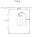
- a resolution is calculated in accordance with the bit map capacity and the print area. For example, if the capacity is 1012 K bytes and the print area is defined as shown in Fig.
- the controller 202 supplies the resolution controller 206 with information that the image data to be sent is for 300 dpi, and sets the rotation speed of the polygon mirror, paper transport speed, laser spot system and the like (step S306).
- the controller 202 receives codes of print character data from the data source via the I/F 201 (step S307).
- the controller 202 develops the bit image data into the bit map memory 205 by using the calculator 204 while ensuring the designated size at the resolution of 300 dpi (step S308). After the bit image data of one page has been developed, the controller 202 actuates the printer engine 207 and sends the data in the bit map memory 205 to the printer engine 207, so that characters are printed at the designated resolution through the printing process of the LBP (step S309).
- the time t shown in Fig. 1 can be determined from the given rotation speed of the polygon mirror because the print area on a recording medium is definitely determined with respect to the timing when a beam detector detects a laser beam and generates a beam detector signal to generate a horizontal synchro signal.
- the controller 202 sends the bit image data to the printer engine 207 so as to start printing dots after the time t . Thereafter, dot data is sent at a clock speed suitable for the determined resolution.
- a series of bit image transfer clocks may be selected from a plurality series of clocks stored in advance.
- the controller 202 sends the bit image to the printer engine 207.
- the whole area of the recording paper is used for printing.
- a user may sometimes wish to use a partial area thereof for printing.
- a partial area defined by 100 mm x 145 mm of one page is intended to be used, the available resolution using the same bit map memory area (1012 K bytes) is given by: 1012 x 1024 x 8 ⁇ 10 ⁇ 145 x 25.4 ⁇ 600 dpi The resolution is therefore doubled.
- the controller 202 causes the resolution controller 206 to set the printing process system at 600 dpi.
- the controller 202 then generates image data for 600 dpi in accordance with the vector information stored in the scalable font 203, the image data being four times as much as that for 300 dpi because image data two times as much as that for 300 dpi are used in both the vertical and horizontal directions.
- image data being four times as much as that for 300 dpi because image data two times as much as that for 300 dpi are used in both the vertical and horizontal directions.
- timings of video clocks for data transfer to the engine there are calculated timings of video clocks for data transfer to the engine, a top margin, left margin, and line length of the recording medium. These calculated parameters are set in a video data transfer circuit so that characters can be printed at the resolution of 600 dpi.
- character data for the partial record area on the recording medium is read and printed in a well known manner.
- characters are printed in one continuous area (in the examples, within one rectangular area). If there are provided a plurality of margin counters and a control system for the counters, characters can be printed in a plurality of separated areas.
- characters are printed on a partial area at a maximum resolution defined by the capacity of the bit map memory.
- a resolution lower than the maximum resolution may be set as desired. For example, if a resolution of 150 dpi is selected under the maximum resolution of 600 dpi, then the bit map memory can be used as four-page full bit map memories at 150 dpi. Further, the time required for bit image development per one page is shortened, thereby improving a throughput of the recording apparatus having a better flexibility in use.
- bit map memory as four-page full bit map memories at 150 dpi, it may be used for the case wherein a window is printed within one page, while ensuring a high resolution depending upon the area of the window. It is to be noted in this case that there is a tradeoff between the development time into the window and the resolution. The maximum resolution for the window is therefore determined in accordance with the memory capacity required for the window which depends on the complexity degree of image data and in accordance with the performance of development circuits.
- Selecting a resolution in the above-described mode may be entered from the operation panel 208 of the LBP, or may be effected by a command supplied from the data source.
- the same resolution is used for both in the vertical and horizontal directions.
- the same resolution is not necessarily required, but different resolutions may be set.
- the present invention is applicable to printers having different resolutions between the vertical and horizontal directions, to printers having a variable resolution either in the vertical direction or in the horizontal direction, by incorporating a suitable algorithm.
- a print operation is executed by determining a resolution from a print area and a memory capacity, thereby providing a recording apparatus capable of changing a resolution while ensuring flexibility in use. Specifically, with a given memory capacity, a small print area and a large print area each can be printed at a maximum allowable resolution. Furthermore, if a resolution selection mode is provided, the recording apparatus more flexible in use can be realized.
- the capacity of the bit map memory in the above embodiments means the capacity of the memory itself or the capacity of an area of the memory allowing to store bit image.
Landscapes
- Engineering & Computer Science (AREA)
- General Engineering & Computer Science (AREA)
- Physics & Mathematics (AREA)
- General Physics & Mathematics (AREA)
- Theoretical Computer Science (AREA)
- Record Information Processing For Printing (AREA)
- Dot-Matrix Printers And Others (AREA)
- Color, Gradation (AREA)
Claims (15)
- Appareil de sortie pour développer des données d'image sur la base de données de code appliquées par une source extérieure et pour enregistrer les données d'image développées sur un support d'enregistrement, l'appareil comprenant :caractérisé parun moyen de stockage (205) pour stocker des données d'image développées ;un moyen (S303 sur la figure 3) pour identifier la capacité dudit moyen de stockage ;un moyen (S306 sur la figure 3) pour déterminer, avant le développement des données d'image, la définition de sortie avec laquelle les données d'image développées doivent être enregistrées en fonction à la fois des dimensions d'une zone d'enregistrement sur le support d'enregistrement et de la capacité identifiée dudit moyen de stockage ; etun moyen (206) pour faire varier la définition de sortie de l'appareil, de manière correspondante ;un moyen (S304 sur la figure 3) pour établir les dimensions de la zone d'enregistrement avec laquelle les données d'image doivent être enregistrées sur le support d'enregistrement.
- Appareil selon la revendication 1, dans lequel le moyen pour déterminer la définition de sortie conduit la définition de sortie à être aussi élevée que possible en fonction de la sortie dudit moyen d'identification.
- Appareil selon la revendication 1 ou la revendication 2, dans lequel le moyen pour établir les dimensions de la zone d'enregistrement sur le support d'enregistrement comporte un moyen pour calculer les synchronisations des marges en fonction de l'information de la position d'impression.
- Appareil selon l'une quelconque des revendications précédentes, dans lequel le moyen de stockage a une capacité de B kilo-octets, et lorsque la zone d'enregistrement a été établie à une aire de X mm x Y mm, on détermine la définition de sortie sous la forme de R points par pouce, en fonction de la formule suivante :
- Appareil selon l'une quelconque des revendications précédentes, dans lequel les données d'image développées sont obtenues à partir d'une police pouvant être mise à l'échelle.
- Appareil selon l'une quelconque des revendications précédentes, dans lequel ledit appareil est une imprimante à faisceau laser.
- Appareil selon l'une quelconque des revendications précédentes, dans lequel ledit appareil est incorporé dans un système comprenant une pluralité d'appareils.
- Appareil selon l'une quelconque des revendications précédentes, comprenant en outre un moyen pour commuter entre un mode dans lequel la définition de sortie est déterminée par ledit moyen de détermination et un mode dans lequel une définition de sortie souhaitée est désignée en réponse à une instruction en provenance de l'extérieur dudit appareil.
- Procédé d'enregistrement de données d'image sur un support d'enregistrement utilisant un appareil de sortie pour développer des données d'image sur la base de données de code appliquées par une source extérieure, pour stocker les données d'image développées dans un moyen de stockage et pour enregistrer les données d'image développées sur une zone d'enregistrement du support d'enregistrement, et ayant une définition variable, le procédé comprenant :l'établissement (S304) des dimensions de la zone d'enregistrement avec laquelle les données d'image doivent être enregistrées sur le support d'enregistrement ;l'identification (S203) de la capacité dudit moyen de stockage ;la détermination (S306), avant le développement des données d'image, de la définition de sortie avec laquelle les données d'image développées doivent être enregistrées en fonction à la fois des dimensions de la zone d'enregistrement et de la capacité identifiée dudit moyen de stockage ; etle stockage des donnés d'image développées dans le moyen de stockage (205).
- Procédé selon la revendication 9, dans lequel la définition de sortie est conduite à être aussi élevée que possible en fonction de la capacité identifiée.
- Procédé selon la revendication 9 ou la revendication 10 et comportant le calcul des synchronisations des marges en fonction d'une information sur la position d'impression.
- Procédé selon l'une quelconque des revendications 9 à 11, dans lequel le moyen de stockage a une capacité de B kilo-octets, et lorsque la zone d'enregistrement a été établie à une aire de X mm x Y mm, détermination de la définition de sortie établie sous la forme de R points par pouce en fonction de l'équation suivante :
- Procédé selon l'une quelconque des revendications 9 à 12, dans lequel les données d'image développées sont obtenues à partir d'une police pouvant être mise à l'échelle.
- Procédé selon l'une quelconque des revendications 9 à 13, dans lequel ledit appareil est une imprimante à faisceau laser.
- Procédé selon l'une quelconque des revendications 9 à 14, comprenant en outre une commutation entre un mode dans lequel la définition de sortie est déterminée par ledit moyen de détermination et un mode dans lequel une définition de sortie souhaitée est désignée en réponse à une instruction en provenance de l'extérieur dudit appareil.
Applications Claiming Priority (2)
| Application Number | Priority Date | Filing Date | Title |
|---|---|---|---|
| JP2095066A JP2647534B2 (ja) | 1990-04-12 | 1990-04-12 | 出力装置 |
| JP95066/90 | 1990-04-12 |
Publications (3)
| Publication Number | Publication Date |
|---|---|
| EP0452131A2 EP0452131A2 (fr) | 1991-10-16 |
| EP0452131A3 EP0452131A3 (en) | 1992-07-29 |
| EP0452131B1 true EP0452131B1 (fr) | 1998-07-08 |
Family
ID=14127634
Family Applications (1)
| Application Number | Title | Priority Date | Filing Date |
|---|---|---|---|
| EP91303216A Expired - Lifetime EP0452131B1 (fr) | 1990-04-12 | 1991-04-11 | Méthode et appareil de sortie |
Country Status (4)
| Country | Link |
|---|---|
| US (1) | US5696888A (fr) |
| EP (1) | EP0452131B1 (fr) |
| JP (1) | JP2647534B2 (fr) |
| DE (1) | DE69129713T2 (fr) |
Families Citing this family (12)
| Publication number | Priority date | Publication date | Assignee | Title |
|---|---|---|---|---|
| JP2821296B2 (ja) * | 1991-12-06 | 1998-11-05 | キヤノン株式会社 | 印刷方法及び装置 |
| KR100208696B1 (ko) * | 1996-09-19 | 1999-07-15 | 윤종용 | 래스터 이미지를 고화질로 인쇄하는 프린터 및 방법 |
| JP3045138B2 (ja) * | 1998-04-01 | 2000-05-29 | ブラザー工業株式会社 | 多機能印刷装置 |
| USD427964S (en) * | 1999-08-23 | 2000-07-11 | Eveready Battery Company, Inc. | Electrochemical cell |
| US7567940B1 (en) * | 1999-10-18 | 2009-07-28 | Stamps.Com | Method and apparatus for on-line value-bearing item system |
| US6247786B1 (en) * | 1999-10-26 | 2001-06-19 | Lexmark International, Inc. | Dynamic pass buffer sizing |
| US7257542B2 (en) | 2000-02-16 | 2007-08-14 | Stamps.Com | Secure on-line ticketing |
| US7031016B1 (en) * | 2000-05-26 | 2006-04-18 | Kabushiki Kaisha Toshiba | System for controlling images according to applications |
| US20060103718A1 (en) * | 2004-11-18 | 2006-05-18 | Xerox Corporation | Variable interlace system and method of use |
| KR101228080B1 (ko) * | 2006-07-25 | 2013-02-01 | 삼성전자주식회사 | 이미지 크기 조절이 가능한 화상형성장치 및 그의 이미지크기 조절 방법 |
| US8483428B1 (en) * | 2010-01-06 | 2013-07-09 | Kimberly Lynn Anderson | Apparatus for processing a digital image |
| US11204722B1 (en) * | 2020-06-04 | 2021-12-21 | Western Digital Technologies, Inc. | Content-aware storage system and method for use therewith |
Family Cites Families (7)
| Publication number | Priority date | Publication date | Assignee | Title |
|---|---|---|---|---|
| JPS5149526B2 (fr) * | 1972-08-05 | 1976-12-27 | ||
| GB2038596B (en) * | 1978-12-20 | 1982-12-08 | Ibm | Raster display apparatus |
| US4546385A (en) * | 1983-06-30 | 1985-10-08 | International Business Machines Corporation | Data compression method for graphics images |
| GB8503867D0 (en) * | 1985-02-15 | 1985-03-20 | Delta Technical Services Ltd | Data loggers |
| JPS63205257A (ja) * | 1987-02-23 | 1988-08-24 | Oki Electric Ind Co Ltd | 印刷制御装置 |
| JP3018337B2 (ja) * | 1988-09-17 | 2000-03-13 | ブラザー工業株式会社 | 画像処理装置 |
| DE4005673C2 (de) * | 1989-02-23 | 1994-02-03 | Minolta Camera Kk | Bilderzeugende Einrichtung mit einem kleindimensionierten Speicher mit einem Bitkarten-Zuweisungssystem |
-
1990
- 1990-04-12 JP JP2095066A patent/JP2647534B2/ja not_active Expired - Fee Related
-
1991
- 1991-04-11 DE DE69129713T patent/DE69129713T2/de not_active Expired - Fee Related
- 1991-04-11 EP EP91303216A patent/EP0452131B1/fr not_active Expired - Lifetime
-
1995
- 1995-05-09 US US08/437,673 patent/US5696888A/en not_active Expired - Lifetime
Also Published As
| Publication number | Publication date |
|---|---|
| DE69129713T2 (de) | 1998-12-17 |
| DE69129713D1 (de) | 1998-08-13 |
| JPH03293170A (ja) | 1991-12-24 |
| EP0452131A3 (en) | 1992-07-29 |
| JP2647534B2 (ja) | 1997-08-27 |
| US5696888A (en) | 1997-12-09 |
| EP0452131A2 (fr) | 1991-10-16 |
Similar Documents
| Publication | Publication Date | Title |
|---|---|---|
| US3999168A (en) | Intermixed pitches in a buffered printer | |
| US5548690A (en) | Printing apparatus | |
| US5841552A (en) | Image processed apparatus for processing images having different resolutions | |
| EP0772156B1 (fr) | Procédé et appareil pour la rotation d'image facsimilé à haute facilité d'adressage | |
| JP3295107B2 (ja) | 画像記録装置 | |
| JPH03246042A (ja) | 画像記録装置 | |
| US5696888A (en) | Variable resolution output method and apparatus | |
| US5136688A (en) | Print data processing apparatus for an image forming apparatus | |
| EP0577087B1 (fr) | Procédé et appareil de sortie | |
| EP0465943B1 (fr) | Dispositif de traitement d'information de texte | |
| EP0510897B1 (fr) | Appareil et méthode de traitement d'images | |
| US6570672B1 (en) | Printing system and method | |
| EP0415725B1 (fr) | Appareil d'enregistrement d'images | |
| US6236755B1 (en) | Output method and apparatus | |
| JPH05110824A (ja) | プリンタの解像度可変方式 | |
| JPH0551919B2 (fr) | ||
| US5946001A (en) | Output apparatus with changeable font resolution | |
| EP0072708B1 (fr) | Imprimante | |
| US5781706A (en) | Reducing memory capacity requirements in image output while maintaining output speed | |
| JP3226226B2 (ja) | 文字処理方法及び装置 | |
| JP3001081B2 (ja) | プリンタ | |
| JP2505362B2 (ja) | ドットパタ―ン出力装置 | |
| JP2621971B2 (ja) | 印刷制御装置 | |
| JPH08194814A (ja) | 画像処理装置 | |
| JPH02238963A (ja) | 画像形成装置 |
Legal Events
| Date | Code | Title | Description |
|---|---|---|---|
| PUAI | Public reference made under article 153(3) epc to a published international application that has entered the european phase |
Free format text: ORIGINAL CODE: 0009012 |
|
| AK | Designated contracting states |
Kind code of ref document: A2 Designated state(s): DE FR GB IT NL |
|
| PUAL | Search report despatched |
Free format text: ORIGINAL CODE: 0009013 |
|
| AK | Designated contracting states |
Kind code of ref document: A3 Designated state(s): DE FR GB IT NL |
|
| 17P | Request for examination filed |
Effective date: 19921221 |
|
| 17Q | First examination report despatched |
Effective date: 19960110 |
|
| GRAG | Despatch of communication of intention to grant |
Free format text: ORIGINAL CODE: EPIDOS AGRA |
|
| GRAG | Despatch of communication of intention to grant |
Free format text: ORIGINAL CODE: EPIDOS AGRA |
|
| GRAH | Despatch of communication of intention to grant a patent |
Free format text: ORIGINAL CODE: EPIDOS IGRA |
|
| GRAH | Despatch of communication of intention to grant a patent |
Free format text: ORIGINAL CODE: EPIDOS IGRA |
|
| GRAA | (expected) grant |
Free format text: ORIGINAL CODE: 0009210 |
|
| AK | Designated contracting states |
Kind code of ref document: B1 Designated state(s): DE FR GB IT NL |
|
| REF | Corresponds to: |
Ref document number: 69129713 Country of ref document: DE Date of ref document: 19980813 |
|
| ITF | It: translation for a ep patent filed | ||
| ET | Fr: translation filed | ||
| PLBE | No opposition filed within time limit |
Free format text: ORIGINAL CODE: 0009261 |
|
| STAA | Information on the status of an ep patent application or granted ep patent |
Free format text: STATUS: NO OPPOSITION FILED WITHIN TIME LIMIT |
|
| 26N | No opposition filed | ||
| REG | Reference to a national code |
Ref country code: GB Ref legal event code: IF02 |
|
| PGFP | Annual fee paid to national office [announced via postgrant information from national office to epo] |
Ref country code: NL Payment date: 20040415 Year of fee payment: 14 |
|
| PGFP | Annual fee paid to national office [announced via postgrant information from national office to epo] |
Ref country code: FR Payment date: 20040421 Year of fee payment: 14 |
|
| PG25 | Lapsed in a contracting state [announced via postgrant information from national office to epo] |
Ref country code: IT Free format text: LAPSE BECAUSE OF NON-PAYMENT OF DUE FEES;WARNING: LAPSES OF ITALIAN PATENTS WITH EFFECTIVE DATE BEFORE 2007 MAY HAVE OCCURRED AT ANY TIME BEFORE 2007. THE CORRECT EFFECTIVE DATE MAY BE DIFFERENT FROM THE ONE RECORDED. Effective date: 20050411 |
|
| PG25 | Lapsed in a contracting state [announced via postgrant information from national office to epo] |
Ref country code: NL Free format text: LAPSE BECAUSE OF NON-PAYMENT OF DUE FEES Effective date: 20051101 |
|
| PG25 | Lapsed in a contracting state [announced via postgrant information from national office to epo] |
Ref country code: FR Free format text: LAPSE BECAUSE OF NON-PAYMENT OF DUE FEES Effective date: 20051230 |
|
| NLV4 | Nl: lapsed or anulled due to non-payment of the annual fee |
Effective date: 20051101 |
|
| REG | Reference to a national code |
Ref country code: FR Ref legal event code: ST Effective date: 20051230 |
|
| PGFP | Annual fee paid to national office [announced via postgrant information from national office to epo] |
Ref country code: DE Payment date: 20090430 Year of fee payment: 19 |
|
| PGFP | Annual fee paid to national office [announced via postgrant information from national office to epo] |
Ref country code: GB Payment date: 20090428 Year of fee payment: 19 |
|
| GBPC | Gb: european patent ceased through non-payment of renewal fee |
Effective date: 20100411 |
|
| PG25 | Lapsed in a contracting state [announced via postgrant information from national office to epo] |
Ref country code: DE Free format text: LAPSE BECAUSE OF NON-PAYMENT OF DUE FEES Effective date: 20101103 |
|
| PG25 | Lapsed in a contracting state [announced via postgrant information from national office to epo] |
Ref country code: GB Free format text: LAPSE BECAUSE OF NON-PAYMENT OF DUE FEES Effective date: 20100411 |