EP0452180A1 - Verfahren zur oberflächlichen Entionisierung von Glasbändern, Vorrichtung dafür und erhaltene entionisierte Produkte - Google Patents
Verfahren zur oberflächlichen Entionisierung von Glasbändern, Vorrichtung dafür und erhaltene entionisierte Produkte Download PDFInfo
- Publication number
- EP0452180A1 EP0452180A1 EP91400823A EP91400823A EP0452180A1 EP 0452180 A1 EP0452180 A1 EP 0452180A1 EP 91400823 A EP91400823 A EP 91400823A EP 91400823 A EP91400823 A EP 91400823A EP 0452180 A1 EP0452180 A1 EP 0452180A1
- Authority
- EP
- European Patent Office
- Prior art keywords
- glass
- ribbon
- anode
- cathodes
- sheet
- Prior art date
- Legal status (The legal status is an assumption and is not a legal conclusion. Google has not performed a legal analysis and makes no representation as to the accuracy of the status listed.)
- Granted
Links
- 239000011521 glass Substances 0.000 title claims abstract description 281
- 238000000034 method Methods 0.000 title claims abstract description 24
- 230000008569 process Effects 0.000 title claims abstract description 10
- 238000002242 deionisation method Methods 0.000 title claims description 24
- 230000005684 electric field Effects 0.000 claims abstract description 23
- 150000002500 ions Chemical class 0.000 claims description 60
- 238000011282 treatment Methods 0.000 claims description 45
- 230000033001 locomotion Effects 0.000 claims description 29
- 239000010410 layer Substances 0.000 claims description 20
- 238000011144 upstream manufacturing Methods 0.000 claims description 13
- 239000005361 soda-lime glass Substances 0.000 claims description 10
- 230000005540 biological transmission Effects 0.000 claims description 8
- 238000006073 displacement reaction Methods 0.000 claims description 7
- 239000000758 substrate Substances 0.000 claims description 7
- 239000003513 alkali Substances 0.000 claims description 5
- ZAMOUSCENKQFHK-UHFFFAOYSA-N Chlorine atom Chemical compound [Cl] ZAMOUSCENKQFHK-UHFFFAOYSA-N 0.000 claims description 2
- PXGOKWXKJXAPGV-UHFFFAOYSA-N Fluorine Chemical compound FF PXGOKWXKJXAPGV-UHFFFAOYSA-N 0.000 claims description 2
- ATJFFYVFTNAWJD-UHFFFAOYSA-N Tin Chemical compound [Sn] ATJFFYVFTNAWJD-UHFFFAOYSA-N 0.000 claims description 2
- 239000000460 chlorine Substances 0.000 claims description 2
- 229910052801 chlorine Inorganic materials 0.000 claims description 2
- 229910052731 fluorine Inorganic materials 0.000 claims description 2
- 239000011737 fluorine Substances 0.000 claims description 2
- AMGQUBHHOARCQH-UHFFFAOYSA-N indium;oxotin Chemical compound [In].[Sn]=O AMGQUBHHOARCQH-UHFFFAOYSA-N 0.000 claims description 2
- 239000011229 interlayer Substances 0.000 claims description 2
- 239000000853 adhesive Substances 0.000 claims 1
- 230000001070 adhesive effect Effects 0.000 claims 1
- 239000002998 adhesive polymer Substances 0.000 claims 1
- 150000001340 alkali metals Chemical class 0.000 abstract 2
- 229910001420 alkaline earth metal ion Inorganic materials 0.000 abstract 2
- 229910052783 alkali metal Inorganic materials 0.000 abstract 1
- 229910001413 alkali metal ion Inorganic materials 0.000 abstract 1
- 239000007789 gas Substances 0.000 description 15
- 229910001415 sodium ion Inorganic materials 0.000 description 13
- CDBYLPFSWZWCQE-UHFFFAOYSA-L Sodium Carbonate Chemical compound [Na+].[Na+].[O-]C([O-])=O CDBYLPFSWZWCQE-UHFFFAOYSA-L 0.000 description 12
- VYPSYNLAJGMNEJ-UHFFFAOYSA-N Silicium dioxide Chemical compound O=[Si]=O VYPSYNLAJGMNEJ-UHFFFAOYSA-N 0.000 description 10
- 238000013508 migration Methods 0.000 description 9
- 230000015572 biosynthetic process Effects 0.000 description 8
- 230000005012 migration Effects 0.000 description 8
- 239000002344 surface layer Substances 0.000 description 7
- 230000009471 action Effects 0.000 description 6
- 229910000029 sodium carbonate Inorganic materials 0.000 description 6
- XLYOFNOQVPJJNP-UHFFFAOYSA-N water Substances O XLYOFNOQVPJJNP-UHFFFAOYSA-N 0.000 description 6
- 238000001035 drying Methods 0.000 description 5
- 239000000377 silicon dioxide Substances 0.000 description 5
- 238000000137 annealing Methods 0.000 description 4
- 230000008901 benefit Effects 0.000 description 4
- 238000010586 diagram Methods 0.000 description 4
- 239000001307 helium Substances 0.000 description 4
- 229910052734 helium Inorganic materials 0.000 description 4
- SWQJXJOGLNCZEY-UHFFFAOYSA-N helium atom Chemical compound [He] SWQJXJOGLNCZEY-UHFFFAOYSA-N 0.000 description 4
- 229920002037 poly(vinyl butyral) polymer Polymers 0.000 description 4
- 230000032683 aging Effects 0.000 description 3
- 238000004458 analytical method Methods 0.000 description 3
- 239000002800 charge carrier Substances 0.000 description 3
- 230000001276 controlling effect Effects 0.000 description 3
- 238000005520 cutting process Methods 0.000 description 3
- 230000007423 decrease Effects 0.000 description 3
- 230000000694 effects Effects 0.000 description 3
- 230000003287 optical effect Effects 0.000 description 3
- 238000012545 processing Methods 0.000 description 3
- 239000000126 substance Substances 0.000 description 3
- 238000005496 tempering Methods 0.000 description 3
- 238000013519 translation Methods 0.000 description 3
- XKRFYHLGVUSROY-UHFFFAOYSA-N Argon Chemical compound [Ar] XKRFYHLGVUSROY-UHFFFAOYSA-N 0.000 description 2
- OYPRJOBELJOOCE-UHFFFAOYSA-N Calcium Chemical compound [Ca] OYPRJOBELJOOCE-UHFFFAOYSA-N 0.000 description 2
- XEEYBQQBJWHFJM-UHFFFAOYSA-N Iron Chemical compound [Fe] XEEYBQQBJWHFJM-UHFFFAOYSA-N 0.000 description 2
- FKNQFGJONOIPTF-UHFFFAOYSA-N Sodium cation Chemical compound [Na+] FKNQFGJONOIPTF-UHFFFAOYSA-N 0.000 description 2
- 230000004888 barrier function Effects 0.000 description 2
- 230000000903 blocking effect Effects 0.000 description 2
- -1 calcium Chemical class 0.000 description 2
- 239000011575 calcium Substances 0.000 description 2
- 229910052791 calcium Inorganic materials 0.000 description 2
- 238000006243 chemical reaction Methods 0.000 description 2
- 150000001875 compounds Chemical class 0.000 description 2
- 238000010438 heat treatment Methods 0.000 description 2
- 230000006872 improvement Effects 0.000 description 2
- 238000009434 installation Methods 0.000 description 2
- 238000004519 manufacturing process Methods 0.000 description 2
- BASFCYQUMIYNBI-UHFFFAOYSA-N platinum Chemical compound [Pt] BASFCYQUMIYNBI-UHFFFAOYSA-N 0.000 description 2
- 229920000642 polymer Polymers 0.000 description 2
- 238000005185 salting out Methods 0.000 description 2
- 238000012360 testing method Methods 0.000 description 2
- 238000005406 washing Methods 0.000 description 2
- VEXZGXHMUGYJMC-UHFFFAOYSA-M Chloride anion Chemical compound [Cl-] VEXZGXHMUGYJMC-UHFFFAOYSA-M 0.000 description 1
- LFQSCWFLJHTTHZ-UHFFFAOYSA-N Ethanol Chemical compound CCO LFQSCWFLJHTTHZ-UHFFFAOYSA-N 0.000 description 1
- DGAQECJNVWCQMB-PUAWFVPOSA-M Ilexoside XXIX Chemical compound C[C@@H]1CC[C@@]2(CC[C@@]3(C(=CC[C@H]4[C@]3(CC[C@@H]5[C@@]4(CC[C@@H](C5(C)C)OS(=O)(=O)[O-])C)C)[C@@H]2[C@]1(C)O)C)C(=O)O[C@H]6[C@@H]([C@H]([C@@H]([C@H](O6)CO)O)O)O.[Na+] DGAQECJNVWCQMB-PUAWFVPOSA-M 0.000 description 1
- KKCBUQHMOMHUOY-UHFFFAOYSA-N Na2O Inorganic materials [O-2].[Na+].[Na+] KKCBUQHMOMHUOY-UHFFFAOYSA-N 0.000 description 1
- 206010063493 Premature ageing Diseases 0.000 description 1
- 208000032038 Premature aging Diseases 0.000 description 1
- 241001639412 Verres Species 0.000 description 1
- 238000010521 absorption reaction Methods 0.000 description 1
- 230000003667 anti-reflective effect Effects 0.000 description 1
- 229910052786 argon Inorganic materials 0.000 description 1
- 239000010425 asbestos Substances 0.000 description 1
- QVGXLLKOCUKJST-UHFFFAOYSA-N atomic oxygen Chemical compound [O] QVGXLLKOCUKJST-UHFFFAOYSA-N 0.000 description 1
- 239000002585 base Substances 0.000 description 1
- 230000008859 change Effects 0.000 description 1
- 238000004140 cleaning Methods 0.000 description 1
- 239000011248 coating agent Substances 0.000 description 1
- 238000000576 coating method Methods 0.000 description 1
- 230000007547 defect Effects 0.000 description 1
- 230000007850 degeneration Effects 0.000 description 1
- 230000008021 deposition Effects 0.000 description 1
- 238000009792 diffusion process Methods 0.000 description 1
- 239000003792 electrolyte Substances 0.000 description 1
- 230000008030 elimination Effects 0.000 description 1
- 238000003379 elimination reaction Methods 0.000 description 1
- 230000002349 favourable effect Effects 0.000 description 1
- 239000005357 flat glass Substances 0.000 description 1
- 239000005329 float glass Substances 0.000 description 1
- 238000005816 glass manufacturing process Methods 0.000 description 1
- 239000001257 hydrogen Substances 0.000 description 1
- 229910052739 hydrogen Inorganic materials 0.000 description 1
- 125000004435 hydrogen atom Chemical class [H]* 0.000 description 1
- PSCMQHVBLHHWTO-UHFFFAOYSA-K indium(iii) chloride Chemical compound Cl[In](Cl)Cl PSCMQHVBLHHWTO-UHFFFAOYSA-K 0.000 description 1
- 230000000977 initiatory effect Effects 0.000 description 1
- 239000011810 insulating material Substances 0.000 description 1
- 229910052742 iron Inorganic materials 0.000 description 1
- JEIPFZHSYJVQDO-UHFFFAOYSA-N iron(III) oxide Inorganic materials O=[Fe]O[Fe]=O JEIPFZHSYJVQDO-UHFFFAOYSA-N 0.000 description 1
- 230000001788 irregular Effects 0.000 description 1
- 239000004973 liquid crystal related substance Substances 0.000 description 1
- 229910044991 metal oxide Inorganic materials 0.000 description 1
- 150000004706 metal oxides Chemical class 0.000 description 1
- 239000000203 mixture Substances 0.000 description 1
- 230000004048 modification Effects 0.000 description 1
- 238000012986 modification Methods 0.000 description 1
- 239000001301 oxygen Substances 0.000 description 1
- 229910052760 oxygen Inorganic materials 0.000 description 1
- 229910052697 platinum Inorganic materials 0.000 description 1
- 239000000843 powder Substances 0.000 description 1
- 238000000197 pyrolysis Methods 0.000 description 1
- 230000009467 reduction Effects 0.000 description 1
- 230000001105 regulatory effect Effects 0.000 description 1
- 229910052895 riebeckite Inorganic materials 0.000 description 1
- 229910052709 silver Inorganic materials 0.000 description 1
- 239000004332 silver Substances 0.000 description 1
- 238000004513 sizing Methods 0.000 description 1
- 239000000344 soap Substances 0.000 description 1
- 239000011734 sodium Substances 0.000 description 1
- 229910052708 sodium Inorganic materials 0.000 description 1
- HPGGPRDJHPYFRM-UHFFFAOYSA-J tin(iv) chloride Chemical compound Cl[Sn](Cl)(Cl)Cl HPGGPRDJHPYFRM-UHFFFAOYSA-J 0.000 description 1
- 238000009827 uniform distribution Methods 0.000 description 1
Images

Classifications
-
- C—CHEMISTRY; METALLURGY
- C03—GLASS; MINERAL OR SLAG WOOL
- C03C—CHEMICAL COMPOSITION OF GLASSES, GLAZES OR VITREOUS ENAMELS; SURFACE TREATMENT OF GLASS; SURFACE TREATMENT OF FIBRES OR FILAMENTS MADE FROM GLASS, MINERALS OR SLAGS; JOINING GLASS TO GLASS OR OTHER MATERIALS
- C03C23/00—Other surface treatment of glass not in the form of fibres or filaments
Definitions
- the invention relates to techniques for surface deionization of flat glass by displacement of ions under the effect of an electric field and, in particular, to the dealkalization of soda-lime glasses.
- deionization will be understood to mean the elimination of alkaline and optionally alkaline-earth ions.
- the dealkalization treatments are carried out in the traditional way to modify the chemical resistance, improve the adhesion of surface deposits or modify certain optical characteristics of the glass.
- the deionization most frequently considered is of the chemical type.
- the glass object is subjected to a solution or an atmosphere reacting with the alkaline ions of the glass. To facilitate the reaction, the operation takes place at a temperature above ambient temperature.
- the phenomenon is as follows: the glass, the temperature of which is controlled, is placed between two electrodes.
- the application of the electric field sets in motion the most easily displaceable ions and, in particular, the alkaline ions.
- the alkaline ions are moved from a surface to the opposite surface of the glass where the cathode is located and form on this surface and in contact with the atmosphere a film of sodium carbonate.
- oxygen and / or hydrogen diffuses (nt).
- the distance between the electrodes and the glass surface can be precisely adjusted.
- the problem of treating the glass surface exists particularly when the glass is in the form of a moving ribbon of glass; in fact, in this case, account must be taken in particular of the speed of movement of the glass ribbon and the distance between the surface of the glass and the electrode, a distance which can vary at any time.
- Patent application EP-A-237 431 proposes a method of surface deionization of such a moving glass ribbon.
- the process described in this patent consists in passing the heated glass ribbon between two identical rectilinear electrodes, or under the two electrodes located on the same side of the ribbon, and to treat one or both sides of the glass ribbon by a corona discharge established by means of a direct current regulated in intensity.
- the fact of controlling the intensity of the current flowing between the electrodes makes it possible to deal with any irregularity in the relative positioning of the glass ribbon and the electrodes.
- the voltage is adjusted so that the intensity is always the same at all times.
- the object of the present invention is a method of surface deionization of a glass ribbon, as well as a device for implementing this method, which make it possible to avoid the abovementioned drawbacks and, in particular, to treat a glass surface in a continuous, reproducible and homogeneous manner to obtain a glass product containing no alkaline and possibly alkaline-earth ions in a surface area to a practically constant depth over the entire width of the treated product.
- the process for deionizing at least one face of a ribbon or a sheet of soda-lime glass consists in passing the ribbon of the heated glass to a temperature below the softening temperature of the glass, in a continuous electric field established between electrodes to generate a corona discharge capable of establishing an electrical connection with the ribbon or the sheet of glass.
- This process is characterized in that the ribbon or the glass sheet is passed in a continuous electric field so as to entrain the alkaline and possibly alkaline-earth ions in the depth and towards the lateral parts of the ribbon or sheet. of glass.
- the glass ribbon thus treated has the particularity of presenting, on the side of its treated face, and over its entire width, a central surface zone containing no alkaline ions and possibly, alkaline-earth, over a depth which depends on the treatment intensity, and lateral surface zones enriched in these ions and carrying a film of sodium carbonate.
- Such a tape has the advantage of providing, continuously, easily, by simply cutting its lateral parts, a large surface of glass containing no alkaline and possibly alkaline-earth ions over a depth which depends on the intensity of treatment. determined based on the intended future use of the glass.
- a device for implementing the surface deionization method according to the invention of at least a face of a ribbon or a sheet of soda-lime glass heated at a temperature below its softening temperature, in relative motion relative to said device, for subjecting it to a continuous electric field established between electrodes rectilinear, parallel to the plane of the ribbon or of the glass sheet, to generate a corona discharge capable of establishing an electrical connection with the ribbon or the glass sheet.
- This device is characterized in that it comprises at least one anode arranged so as to cover the central part of the ribbon or of the glass sheet and at least two cathodes arranged so as to cover, each, a lateral region of the ribbon or of the glass sheet, these cathodes being offset longitudinally and transversely from the adjacent ends of the anode.
- the device comprises, in particular, means for scrolling the ribbon or the sheet of hot glass in the electric field.
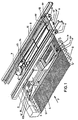
- Figure 1 shows a device according to the invention disposed above a glass ribbon (1) whose surface must be deionized.
- the glass moves on conveyor rollers (2) or any other means allowing the glass to move.
- the device represented in FIG. 1, comprises an electrode holder (3) on which are mounted supports (3 ′) for rectilinear electrodes (anode and cathodes), parallel to the plane of the glass ribbon.
- These electrodes, an anode (4) and two cathodes (5), are mounted so that the anode covers the central part of the glass ribbon and that the cathodes, of dimension smaller than that of the anode, each cover , a lateral region of the glass ribbon, these cathodes being offset longitudinally and transversely from the adjacent ends of the anode.
- the longitudinal axis of the eletrodes is perpendicular to the direction of movement of the glass ribbon and the two cathodes are located upstream of the anode relative to the direction of movement of the glass ribbon (represented by the arrow F) .
- This arrangement of the electrodes constitutes one of the embodiments of the invention, modes which will be described later.
- the electrode holder (3) is mounted on a block (6) of the turret type which makes it possible to move the electrodes, on the one hand, perpendicular to the plane of the glass ribbon, so as to increase or decrease the distance between the surface of the glass and the electrodes and, on the other hand, by rotation about an axis (7) perpendicular to the plane of the glass ribbon, in particular to modify the inclination of the anode.
- the turret (6) is itself integral with a translation device (8) which makes it possible to move the electrode holder / turret group transversely to the glass ribbon.
- the block (6) of the turret type may comprise, for example, a telescopic cylinder (9) making it possible to preposition the electrode holder, this cylinder being associated with a stepping motor to obtain a fine adjustment of the position of the electrodes relative to the surface of the glass.
- the translation device (8) can comprise, for example, a carriage (10) movable on rails (11) by means of rollers (12).
- the rails are fixed by any suitable means to the superstructure of the glass manufacturing installation.
- the carriage (10) carries the turret block (6) which is integral with a pulley (13) of which the axis of rotation corresponds to that of the turret.
- the pulley (13) can rotate under the action of another pulley (15), the rotation of which is transmitted to the pulley (13) by a cable (14).
- knobs (16, 16 ′) for translating and blocking the carriage knobs (17, 17 ′) for rotating and locking the turret (6) coupled to the pulley (15) and rollers (18) and (19) for controlling the horizontality of the carriage (10) and for locking the rails (11).
- This translation device allows, in addition to the movement of the turret block (6) transversely to the glass ribbon (1), to place this block (6) after being lifted by the jack (9), outside the production line to change electrodes for example.
- the electrode holder (3) comprises means for moving the cathodes relative to the anode. These means are constituted, for example, by a set of crossed lights (20), which allows parallel and perpendicular displacements of the cathodes (5) relative to the anode (4) or which makes it possible to tilt the cathodes on the direction of movement of the glass ribbon and relative to the anode.
- any known suitable system can be used, that represented in FIG. 1 and described above constituting only one possible embodiment.
- the electrodes, anode (4) and cathodes (5) are each mounted pendulumly about an axis (21, 22) secured to the electrode holder.
- the electrodes being at a short distance from the surface of the glass ribbon, this arrangement makes it possible to separate the electrodes from the surface of the glass when the latter has irregularities, and thus avoid contact with the surface of the glass. which can lead to blockage of the glass sheet.
- the electrodes touch the glass, they pivot about their respective axis (21, 22), being driven by the glass ribbon.
- the cylinder can then be actuated to move the electrodes away.
- Electrodes useful in the device according to the invention include a transverse cavity, connected to a source of plasma gas and opening, opposite the glass ribbon, by an opening in which the gas flows perpendicular to the ribbon or at another inclination, this opening opening from the electrode at the connection of a vertical wall and a wall inclined on the plane of the glass ribbon.
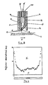
- the electrode (30) has a section in the shape of a rectangular trapezoid, the bases of which are oriented perpendicular to the plane of the glass ribbon.
- the electrode (30) comprises a transverse cavity (31) bounded by vertical walls (32, 33) and by an inclined wall (34).
- the upper wall (35) of the cavity is pierced with at least one orifice (36) through which the cavity (31) is connected to a source of plasma gas, not shown.
- the cavity (31) opens near the surface of the glass ribbon through a transverse opening (37) in which the gas flows in an inclination which can be 90 ° as shown in the figure or else of another value, less than 90 °, to oppose the driving movement of the glass ribbon.
- This opening (37) ends in two lips (38 and 39) located one opposite the other.
- the electrode due to its trapezoidal shape, oriented as described above, has an inclined part which is close to the zone where the corona discharge takes place, which has the advantage, in particular, of facilitating the formation of this discharge. .
- the lower part of the electrode constituted by the edges of the vertical (32) and inclined (34) transverse walls has a rounded shape. This configuration has the advantage of facilitating the attachment of the crown discharge.
- the opening (37) located at the bottom of the electrode (30) can be constituted by a single slot, by a plurality of holes of square, rectangular or circular section or by a plurality of nozzle tubes. emerging from the lips of the electrode, with an axis perpendicular to the plane of the glass ribbon.
- the opening (37) must have a width which makes it easier to attach the discharge and to obtain a high gas speed at the outlet of the opening, favorable to the stability of the discharge .
- This width can be between 0.1 and 0.8 mm. A width less than 0.1 mm does not allow the discharge to be hooked at the opening.
- the width of the opening is advantageously greater than 0.3 mm.
- the opening consists of a plurality of holes or nozzle tubes
- these are preferably distributed regularly over the entire length of the electrode.
- the distance between these holes or these nozzle tubes may vary; it is however preferred that this difference is small, in order to increase the number of holes or of nozzle tubes and consequently, the attachment zones of the discharge. This difference can vary, for example between 0.1 mm and 0.5 mm.
- the opening (37) of the electrode (30) consists of a plurality of holes with a square section of 0.5 mm side, spaced at a distance of 0.5 mm.
- the cavity (31) of the electrode (30) advantageously contains a gas distributor (40) which is constituted by any means allowing a uniform distribution of the plasma gas over the entire length of the electrode, for example a threaded rod.
- the electrode may be surrounded by skirts (41), of electrical insulating material, having the height of the electrode, to protect the crown discharge and confine it in a restricted area, directly above the glass ribbon to be treated.
- the glass ribbon moves under the electrode in the direction indicated by the arrow in Figure 2, but it can also move in the opposite direction.
- the electrodes are arranged parallel to the plane of the glass ribbon, the anode so as to cover the central part of the glass ribbon and the cathodes so as to cover the lateral regions. glass ribbon.
- the cathodes are, moreover, offset longitudinally and transversely from the adjacent ends of the anode. Different configurations are possible with the anode and the cathodes located above or below the glass.
- FIG. 3 shows, by way of examples, diagrams 3a to 3 g of different possible positions of the electrodes.
- the electrodes, anodes and cathodes are arranged perpendicular to the direction of movement of the glass ribbon, represented by the arrow F and the anode A is placed above the central part of the glass ribbon.
- the cathodes (C) can be located upstream (fig. 3a) or downstream (fig. 3b) of the anode A relative to the direction of movement of the glass ribbon.
- four electrodes are arranged two by two symmetrically at the anode.
- the anode is arranged above the face of the glass ribbon to be treated and the cathodes, (shown in dotted lines --- in fig.
- the cathodes may or may not be inclined in the direction of movement of the ribbon, as shown in dotted lines (-.-) in FIGS. 3a to 3c.
- the cathodes are shown in dotted lines to indicate that they are located under the glass ribbon. It goes without saying that, in this position, the cathodes can also be inclined.
- the anode is inclined in the direction of movement of the glass ribbon and the two cathodes are parallel to each other and arranged one upstream and the other downstream of the anode. It is possible that the cathodes are parallel to the anode (fig. 3e and 3f) or else inclined with respect to the anode (fig. 3g).
- the electrodes are mounted on an electrode holder (3), as shown in FIG. 1, which comprises a second cathode support (3 ′).
- the cathodes can have a greater length to increase the intensity of current at equal voltage.
- diagrams 3a to 3g there is shown the anode disposed above the glass ribbon. It should be noted that it is also possible to place it under the glass ribbon.
- the cathodes are longitudinally and transversely offset from the adjacent ends of the anode.
- the ends of the cathodes are spaced transversely by a distance d1 and longitudinally by a distance d2 from the adjacent ends of the anode.
- distances d1 and d2 are determined as a function of the applied voltage in order to avoid the formation of electric arcs.
- the distance d2 may be, at the limit, zero.
- the dealkalization treatment is more homogeneous when the distance d2 increases; it is therefore advantageous that, longitudinally, the ends of the cathodes are distant from the adjacent ends of the anode.
- the appropriate value of d it must also be taken into account that, when the distance d, increases, the voltage which must be applied also increases and, consequently, the power of the generator, which can cause problems of sizing and security.
- the distance d2 also depends on the temperature of the glass. Indeed, if the temperature of the glass decreases, the electrodes must be brought together to work at a given voltage.
- the distance d1 that is to say the transverse deviation between the adjacent ends of the anode and the cathodes, could vary between 1.5 and 5 cm and the distance d2, longitudinal deviation between the adjacent ends of the anode and the cathodes, was advantageously greater than 5 cm .
- the cathodes are located upstream and downstream of the anode. It is advantageous, according to the invention, to have the longitudinal axis of the cathodes upstream of the anode at a distance (h1) from the axis of the anode less than that (h2) existing between the anode and the cathode disposed downstream of the anode, as shown in Figure 3 f.
- the length of the electrodes depends on the width of the glass ribbon to be treated.
- the length of the anode should be as large as possible because the area of glass treated corresponds to the part of the glass ribbon located under the anode.
- the cathodes cover the lateral parts of the glass ribbon which correspond to the zones of the glass ribbon towards which the alkali and alkaline earth ions migrate and on the surface of which sodium carbonate is formed. These parts are intended to be removed later by cutting.
- the lengths of the cathodes must therefore be much shorter than that of the anode so as not to limit the area treated.
- the total length of the anode and the cathodes must take account of the transverse deviation d1 between the adjacent ends of the anode and the cathodes and, of course, the width of the glass ribbon.
- distance d3 corresponds to the transverse distance between the cathodes and the edge of the glass ribbon. Indeed, when the glass (1) is driven by rollers (2) (fig. 1), the proximity of the cathodes to the edge of the glass ribbon can cause a short circuit if the rollers are not insulated. This distance d3 can vary between 0, if the drive rollers are insulated, and approximately 3 cm when they are not.
- the glass is treated in a similar manner, that is to say as described above, that the glass comprises a central surface zone which does not contain alkaline and alkaline-earth ions and two lateral surface zones enriched in these ions.
- FIG. 4 represents a concentration profile of the displaced sodium ions. This profile is obtained by analysis by electronic microprobe. On the abscissa is given the dimension of the anode, to which the zone of the deionized glass corresponds. On the ordinate, the deionized depths (in nm) and therefore corresponding to only part of the thickness of the glass are indicated. This profile delimits two zones. Zone I corresponds to the depth of dealkalized glass, zone II to a region of glass which has not undergone the treatment, the ions which migrate under the action of the electric field moving in block first towards the other side of the glass ribbon, then towards the side parts not shown in the figure.
- the method according to the invention consists in passing a heated glass ribbon through a continuous electric field, established between rectilinear electrodes to generate a corona discharge capable of establishing an electrical connection with the glass ribbon, to move the ions deep into the ribbon and to the side portions of the glass ribbon.
- the glass ribbon To deionize the surface of a glass ribbon, it must be heated to a temperature sufficient to allow the migration of ions. Generally, the glass is heated to a temperature below its softening temperature.
- the temperature is above 400 ° C to allow the migration of alkaline ions and alkaline earth ions.
- temperatures below 400 ° C only the alkaline ions migrate under the action of the electric field.
- Such a treatment at a temperature below 400 ° C. may be of interest, depending on the intended future use since the presence of alkaline earth ions, such as calcium, makes it possible to improve the adhesion of the layers subsequently deposited.
- the deionization treatment of the glass ribbon is advantageously carried out on the glass-making installation itself, for example at the outlet of the float oven and before the entry of the drying rack.
- the temperature of the glass is of the order of 600 ° to 700 ° C., a temperature which is suitable for the treatment according to the invention.
- the distance between the electrodes and the surface of the glass must be carefully adjusted since this distance defines the space in which the corona discharge is formed and since the stability and homogeneity of this discharge necessary to allow uniform and continuous treatment depend on it .
- the glass ribbon can move on conveyor rollers and consequently has undulations. It is important that the electrodes are not in contact with the glass surface. The distance must therefore be sufficient to avoid contact. However, a small electrode-glass distance facilitates the initiation of the discharge with a low voltage, thus limiting the risks of arcing. This distance should not be too great to avoid the risk of degeneration of the discharge. To meet all these requirements, the distance between the electrodes and the glass surface can advantageously be between 2 and 4 mm approximately.
- the electrodes are connected to a source of plasma gas. Any plasma gas can be used. However, in the invention, in order to obtain a stable discharge, in particular for electrodes situated at a distance of between 2 and 4 mm from the surface of the glass, it is preferred to use helium at the anode and argon or helium at the cathodes.
- the speed of the gas at the outlet of the electrode is preferably high in order to obtain good stability of the discharge. This can be obtained in particular by using electrodes whose opening (37) is formed of a plurality of holes of small cross section, as indicated above. It is also advantageous for the treatment to be carried out in a closed enclosure to prevent drafts of air leaving the oven and air movements due to the speed of the glass ribbon disturbing the regular and homogeneous gas supply. .
- a direct current is used for the deionization treatment, the intensity of which is adjusted as a function of the resistance of the glass.
- the tension is limited to a value determined as a function of the desired treatment intensity, evaluated, for a given glass at a determined temperature, by the quantity of coulomb charges applied to the glass per unit of area.
- the glass being grounded the potential is floating, that is to say that it is not fixed relative to the mass in order to be able to create a double positive and negative plasma on the surface of the glass. .
- the voltage is as high as possible, within the limit imposed, to obtain an intense treatment, while taking into account in particular the arrangement of the electrodes to avoid the formation of electric arcs.
- the resistance of the glass according to which the intensity is adjusted according to the invention depends on the temperature of the glass, the rate of alkaline and alkaline-earth ions, the speed of movement of the glass ribbon and the width of glass to be treated, that is to say the width of glass located under the anode.
- the last two parameters determine the speed of movement of the glass ribbon which can vary from 3 to 25 m / min and the width of glass to be treated which can reach approximately 3 m, determine the number of ions, or charge carriers, available, per unit of time, under the electrodes, and therefore the conductance of the glass. If the speed and the width of the ribbon increase, the number of charge carriers increases and, consequently, the conductance.
- the deionization treatment that is to say the migration of these charge carriers, then requires a higher current intensity, and consequently a greater power generator. If one wishes to use a limited intensity, it is necessary to control these factors of speed of movement and width to be treated so that they do not increase together until they require high power.
- the temperature of the glass to be treated it is advantageous for it to be as high as possible, while remaining below the softening temperature of the glass, to allow the migration of the ions. Too high a temperature, however, can cause problems during the annealing treatment subsequent to deionization, as will be described later.
- the deionization treatment according to the invention makes it possible to create, on the surface of the glass, a layer free of alkaline and possibly alkaline-earth ions. This results in the formation of a surface layer enriched with silica.
- the nature of the other face of the glass is not modified by the treatment, which has the advantage of avoiding premature aging of this face.
- the glass ribbon treated according to the invention has the particularity of having, on the side of its treated face, and over its entire width, a central surface area not containing alkali and alkaline earth ions on a depth which depends on the intensity of the treatment, and two lateral surface zones enriched with displaced ions and carrying a film of sodium carbonate. These lateral zones can be removed later by cutting, which makes it possible to obtain a product treated almost regularly on the surface.
- the thickness of treated glass depends, for a given glass at a determined temperature, on the intensity of the treatment which is measured by the number of coulombs applied to the glass per unit area. It therefore depends on the speed of movement of the glass ribbon, the intensity of the current and the width of glass to be treated, factors mentioned previously.
- the remigration of alkaline ions is however limited by the alkaline earth ions which, as indicated above, migrate less than the sodium ions, under the action of an electric field and constitute, a front blocking the remigration of the alkaline ions.
- the values of thickness of treated glass, indicated in the present request, take account of this remigration and are evaluated after annealing.
- a subsequent treatment of the deionized glass in particular a tempering treatment by contact, which takes place for example at 650 ° C. for 2 to 3 minutes does not destroy the deionization of the glass surface, but only reduces it . It is possible to attenuate the remigration of the alkaline ions during tempering, by anticipating the remigration of the ions during the annealing, for example by acting on the temperature of the glass and the intensity of the treatment during the dealkalization.
- the glass is at a temperature of 700 ° C.
- the electrodes are arranged in the configuration shown in Figure 3a.
- the electrodes are straight and as shown in FIG. 2, the opening (37) being formed by a slot of 0.5 mm.
- the distance between electrodes and the glass surface is 3 mm.
- the anode is 100 cm long and the cathodes 3 cm long.
- the ends of the cathodes are spaced from the adjacent end of the anode, transversely by a distance d1 equal to 2 cm and longitudinally by a distance d2 equal to 18 cm.
- the anode is supplied with helium at a flow rate of 70 l / min.
- the cathodes are also supplied with helium at a flow rate of 2 to 3 l / min.
- the starting voltage of the crown discharge is 900 V and the operating voltage limited to 1050 V.
- the intensity is, on average, 5 A.
- the crown discharge obtained is stable and homogeneous over the entire width of the treated glass .
- the thickness of glass treated is 20 nm, a value determined after passing the glass through the drying rack.
- the glass ribbon described in Example 1 scrolls, at the same speed, under electrodes arranged as shown in FIG. 3e.
- the anode and the cathodes are identical to those of Example 1.
- the longitudinal axis of the anode forms an angle 0 of 30 ° with the perpendicular to the direction of movement of the glass ribbon.
- the ends of the cathodes are located at a distance from the adjacent ends of the anode, transversely of 2 cm and longitudinally of 25 cm.
- the applied voltage is 1260 V and the intensity is 3 A on average.
- the thickness of treated glass is 20 nm.
- the cathode situated upstream of the anode was brought together so that it is longitudinally distant from the anode by a distance h1 of approximately 20 cm (see FIG. 3f).
- the deionization of a glass ribbon has been described more particularly using electrodes comprising an opening (37) in the form of a slot. It is also possible to use electrodes having an opening having another configuration, as described above, and in particular an opening formed by a plurality of holes, particularly of square section, which makes it possible to obtain, in particular, better attachment of the discharge. crown and control the speed of the gas emerging from these orifices.
- the voltage limitation also makes it possible to reduce the number of rollers which must be insulated to avoid any short circuit.
- the treated surface of the glass has a width of 100 cm.
- the deionization treatment over a greater width can be envisaged according to the invention, by adapting the parameters such as the voltage and the intensity of the electric current.
- the deionization treatment allows the formation, on the side of the treated face, of a surface layer not containing alkaline and alkaline-earth ions, which results in a surface layer enriched with silica.
- This layer gives the glass a certain number of properties, in particular optical, physicochemical and mechanical.
- the light transmission can be increased up to 1.5% for a deionized thickness of 100 nm, per treated surface.
- the physicochemical properties better adhesion of the layers deposited subsequently on the treated glass is obtained and good resistance to aging of the treated glass.
- the alkaline earth ions such as calcium, which migrated during the treatment, which control the remigration of alkaline ions.
- the alkaline ions thus remain blocked at the front formed by the alkaline earth ions.
- the presence of the surface layer enriched with silica allows the use of the glass treated according to the invention, without requiring the deposition of a specific layer serving as a barrier to sodium ions, in products with an electroconductive coating, such as heated glazing, low-emissivity glazing, products for electronics, in particular liquid crystal display devices, in which the migration of sodium ions contained in the glass to layers deposited subsequently must be avoided.
- the glasses according to the invention can be used as horticultural glass when such light transmission is necessary, as glazing for motor vehicles, as anti-reflective glazing for buildings and cars and also in particular fields such as that of glasses. for electronics such as photovoltaic cells. Processing these glasses to a depth of 100 nm is sufficient.
- the better adhesion of layers deposited on the surface of the treated glass leads to the use of these glasses in laminated glazings which include an interlayer sheet of polymer, for example polyvinyl butyral (PVB), and in mirrors for the adhesion of the layers. based on silver.
- PVB polyvinyl butyral
- a thickness of treated glass from 20 nm to 30 nm is suitable.
- Table I relates to an extra-clear glass ("Albarino" glass trademark registered by SAINT-GOBAIN, comprising 0.0150% iron in the form of Fe2O3) useful for photovoltaic products.
- the table gives the optical properties of extra-clear glass before and after deionization treatment. There is an improvement in light transmission (TL), the transmission energy factor (FET) and the solar factor (FS).
- the treated glass has a lower energy reflection factor (FER), light reflection (RL) and energy absorption factor (FEA).
- Table 2 relates to laminated glazings for aviation and for the automobile, the glass substrate of which has been treated and untreated and for which the peeling forces of the polymer sheet (polyvinyl butyral) have been measured.
- a treated glass coated with PVB has an increase in peel strength greater than or equal to 100%.
- the resistance of a deionized glass according to the invention is evaluated with regard to electrolytes.
- the test is carried out in a cell whose walls are formed by the faces of the glass.
- the cell is filled with high resistivity water, maintained at 90 ° C.
- immerse two platinum electrodes In the water, immerse two platinum electrodes.
- the whole is thermostatically controlled and the evolution of the conductivity is monitored over time, that is to say the possible passage, in water, of ions originating from the faces of the treated glass. The time from which the conductivity of the water changes suddenly is noted.
- a sodium ion salting-out test is also carried out, according to which the mass of salting-out sodium ions is measured in 24 h at 95 ° C. in the previous cell, reduced to the unit of surface area of the glass.
- the present invention has been described for the treatment of a moving glass ribbon. It is understood that the method and the device according to the invention can also be used for the treatment of stationary glass sheet, in which case, the device according to the invention is movable relative to the glass. The important thing is that the glass support and the device are in relative movement with respect to each other.
- a conductive layer for example a layer of metal oxide such as indium tin oxide (ITO) or oxide of tin doped for example with fluorine or chlorine, by known methods, in particular by pyrolysis of metallic compounds in the form of solution, powder or vapor.
- ITO indium tin oxide
- the glazing obtained can then be used as low-emissivity glazing, especially for buildings, and as electrically conductive glazing, in particular heating for example for windshields.
- the glass treated according to the invention which comprises a surface layer enriched with silica, it is not necessary to deposit a barrier layer with sodium ions before the formation of the conductive layer.
- the conductive layers formed on the glass treated according to the invention are obtained from metallic compounds such as tin chloride, indium chloride, no defect of the white haze type is observed in the final layer. which is due to the reaction between the chloride ions and the sodium ions contained in an untreated glass according to the invention.
- the two sides of the glass ribbon are to be treated, it is possible to have under the glass ribbon, in an area immediately adjacent to that of the first treatment or in a more distant area, a device similar to that described above. .
- the sodium ion concentration profile, for the second side treated is similar to that of the first side treated, but reversed, zone II (fig. 4) located in the thickness of the glass remaining untreated. .
- a glass is thus obtained comprising two surface layers enriched with silica, having the properties mentioned above.
- such a glass has a very improved light transmission which can be, for example, in the case of float glass, of 91.5% for a deionized thickness of 100 nm per treated surface.
Landscapes
- Chemical & Material Sciences (AREA)
- Life Sciences & Earth Sciences (AREA)
- Engineering & Computer Science (AREA)
- Chemical Kinetics & Catalysis (AREA)
- General Chemical & Material Sciences (AREA)
- Geochemistry & Mineralogy (AREA)
- Materials Engineering (AREA)
- Organic Chemistry (AREA)
- Surface Treatment Of Glass (AREA)
- Cell Separators (AREA)
Applications Claiming Priority (2)
| Application Number | Priority Date | Filing Date | Title |
|---|---|---|---|
| FR9004416 | 1990-04-06 | ||
| FR9004416A FR2660649B1 (fr) | 1990-04-06 | 1990-04-06 | Procede pour la desionisation superficielle d'un ruban de verre, dispositif pour sa mise en óoeuvre et produits desionises obtenus. |
Publications (2)
| Publication Number | Publication Date |
|---|---|
| EP0452180A1 true EP0452180A1 (de) | 1991-10-16 |
| EP0452180B1 EP0452180B1 (de) | 1995-08-30 |
Family
ID=9395498
Family Applications (1)
| Application Number | Title | Priority Date | Filing Date |
|---|---|---|---|
| EP19910400823 Expired - Lifetime EP0452180B1 (de) | 1990-04-06 | 1991-03-27 | Verfahren zur oberflächlichen Entionisierung von Glasbändern, Vorrichtung dafür und erhaltene entionisierte Produkte |
Country Status (4)
| Country | Link |
|---|---|
| EP (1) | EP0452180B1 (de) |
| DE (1) | DE69112474T2 (de) |
| ES (1) | ES2079043T3 (de) |
| FR (1) | FR2660649B1 (de) |
Cited By (3)
| Publication number | Priority date | Publication date | Assignee | Title |
|---|---|---|---|---|
| FR2696441A1 (fr) * | 1992-10-02 | 1994-04-08 | Saint Gobain Vitrage Int | Désalcalinisation de feuilles de verre à faible teneur en alcalins. |
| FR2696443A1 (fr) * | 1992-10-02 | 1994-04-08 | Saint Gobain Vitrage Int | Substrat en verre, obtenu par désalcalinisation, utilisé dans le domaine électronique. |
| CN100358821C (zh) * | 2002-01-25 | 2008-01-02 | 法国圣戈班玻璃厂 | 无机基体上的有机污染的处理 |
Families Citing this family (4)
| Publication number | Priority date | Publication date | Assignee | Title |
|---|---|---|---|---|
| DE102010011192B4 (de) | 2010-03-11 | 2013-05-16 | Schott Ag | Verfahren zur Oberflächenbehandlung von Substraten |
| DE102015007832A1 (de) | 2015-06-18 | 2016-12-22 | Optoflux GmbH | Optisches Bauteil und Verfahren zur Herstellung eines optischen Bauteils im Mehrschicht-Spritzgussverfahren |
| WO2021154698A1 (en) | 2020-01-31 | 2021-08-05 | Corning Incorporated | High throughput electro-thermal poling |
| CN115611231B (zh) * | 2022-10-31 | 2025-06-06 | 华东光电集成器件研究所 | 一种soi硅片与玻璃的晶圆级键合方法 |
Citations (2)
| Publication number | Priority date | Publication date | Assignee | Title |
|---|---|---|---|---|
| EP0001837A2 (de) * | 1977-11-02 | 1979-05-16 | Battelle-Institut e.V. | Verfahren zur Entspiegelung von Gläsern sowie Vorrichtung zur Durchführung eines solchen Verfahrens |
| FR2616144A1 (fr) * | 1987-06-02 | 1988-12-09 | Saint Gobain Emballage | Desionisation du buvant de recipients en verre |
-
1990
- 1990-04-06 FR FR9004416A patent/FR2660649B1/fr not_active Expired - Fee Related
-
1991
- 1991-03-27 EP EP19910400823 patent/EP0452180B1/de not_active Expired - Lifetime
- 1991-03-27 DE DE1991612474 patent/DE69112474T2/de not_active Expired - Fee Related
- 1991-03-27 ES ES91400823T patent/ES2079043T3/es not_active Expired - Lifetime
Patent Citations (2)
| Publication number | Priority date | Publication date | Assignee | Title |
|---|---|---|---|---|
| EP0001837A2 (de) * | 1977-11-02 | 1979-05-16 | Battelle-Institut e.V. | Verfahren zur Entspiegelung von Gläsern sowie Vorrichtung zur Durchführung eines solchen Verfahrens |
| FR2616144A1 (fr) * | 1987-06-02 | 1988-12-09 | Saint Gobain Emballage | Desionisation du buvant de recipients en verre |
Cited By (5)
| Publication number | Priority date | Publication date | Assignee | Title |
|---|---|---|---|---|
| FR2696441A1 (fr) * | 1992-10-02 | 1994-04-08 | Saint Gobain Vitrage Int | Désalcalinisation de feuilles de verre à faible teneur en alcalins. |
| FR2696443A1 (fr) * | 1992-10-02 | 1994-04-08 | Saint Gobain Vitrage Int | Substrat en verre, obtenu par désalcalinisation, utilisé dans le domaine électronique. |
| WO1994007806A1 (fr) * | 1992-10-02 | 1994-04-14 | Saint-Gobain Vitrage International | Substrat en verre, obtenu par desalcalinisation, utilise dans le domaine electronique |
| WO1994007807A1 (fr) * | 1992-10-02 | 1994-04-14 | Saint-Gobain Vitrage International | Desalcalinisation de feuilles de verre a faible teneur en alcalins |
| CN100358821C (zh) * | 2002-01-25 | 2008-01-02 | 法国圣戈班玻璃厂 | 无机基体上的有机污染的处理 |
Also Published As
| Publication number | Publication date |
|---|---|
| EP0452180B1 (de) | 1995-08-30 |
| DE69112474D1 (de) | 1995-10-05 |
| FR2660649A1 (fr) | 1991-10-11 |
| FR2660649B1 (fr) | 1992-06-12 |
| DE69112474T2 (de) | 1996-05-02 |
| ES2079043T3 (es) | 1996-01-01 |
Similar Documents
| Publication | Publication Date | Title |
|---|---|---|
| EP2438024B1 (de) | Verfahren zur abscheidung eines dünnen films | |
| EP0397292B1 (de) | Verfahren zur Herstellung einer dünnen Metalloxidbeschichtung auf einem Substrat, insbesondere Glas und deren Verwendung als Verglasung | |
| CA2924811A1 (fr) | Procede d'obtention d'un substrat revetu par un empilement comprenant une couche d'oxyde transparent conducteur | |
| CA2806269C (fr) | Procede d'obtention d'un materiau comprenant un substrat muni d'un revetement | |
| EP2792650A1 (de) | Verfahren zur Aufbringung einer Dünnschicht, und so erhaltenes Produkt | |
| CA2849422A1 (fr) | Procede de traitement thermique de couches d'argent | |
| EP0452180B1 (de) | Verfahren zur oberflächlichen Entionisierung von Glasbändern, Vorrichtung dafür und erhaltene entionisierte Produkte | |
| FR2956556A1 (fr) | Procede d'obtention d'un vitrage chauffant | |
| EP0237431B1 (de) | Entionisierung von Glas durch Corona-Entladung | |
| WO2010103237A1 (fr) | Procédé de dépôt de couche mince | |
| EP3192095A1 (de) | Temperverfahren mit blitzlampen | |
| EP1366220A1 (de) | Verfahren zum ätzen von schichten auf transparenten substraten des typs glassubstrat | |
| FR2696441A1 (fr) | Désalcalinisation de feuilles de verre à faible teneur en alcalins. | |
| WO2020070393A1 (fr) | Procede d'obtention d'une feuille de verre revetue d'une couche fonctionnelle | |
| EP3917893B1 (de) | Verfahren zur herstellung eines mit einer funktionalen schicht beschichteten substrats | |
| WO2020157424A1 (fr) | Procede d'obtention d'un substrat revetu d'une couche fonctionnelle | |
| FR2670200A1 (fr) | Procede de formation d'une couche semi-conductrice d'oxyde de zinc dope a l'aluminium sur du verre, vitrage ainsi obtenu. |
Legal Events
| Date | Code | Title | Description |
|---|---|---|---|
| PUAI | Public reference made under article 153(3) epc to a published international application that has entered the european phase |
Free format text: ORIGINAL CODE: 0009012 |
|
| AK | Designated contracting states |
Kind code of ref document: A1 Designated state(s): BE CH DE ES FR GB IT LI LU SE |
|
| 17P | Request for examination filed |
Effective date: 19911213 |
|
| 17Q | First examination report despatched |
Effective date: 19940912 |
|
| RAP1 | Party data changed (applicant data changed or rights of an application transferred) |
Owner name: SAINT-GOBAIN VITRAGE |
|
| GRAA | (expected) grant |
Free format text: ORIGINAL CODE: 0009210 |
|
| AK | Designated contracting states |
Kind code of ref document: B1 Designated state(s): BE CH DE ES FR GB IT LI LU SE |
|
| REF | Corresponds to: |
Ref document number: 69112474 Country of ref document: DE Date of ref document: 19951005 |
|
| ITF | It: translation for a ep patent filed | ||
| REG | Reference to a national code |
Ref country code: CH Ref legal event code: NV Representative=s name: KIRKER & CIE SA |
|
| REG | Reference to a national code |
Ref country code: ES Ref legal event code: FG2A Ref document number: 2079043 Country of ref document: ES Kind code of ref document: T3 |
|
| GBT | Gb: translation of ep patent filed (gb section 77(6)(a)/1977) |
Effective date: 19951208 |
|
| PLBE | No opposition filed within time limit |
Free format text: ORIGINAL CODE: 0009261 |
|
| STAA | Information on the status of an ep patent application or granted ep patent |
Free format text: STATUS: NO OPPOSITION FILED WITHIN TIME LIMIT |
|
| 26N | No opposition filed | ||
| PGFP | Annual fee paid to national office [announced via postgrant information from national office to epo] |
Ref country code: SE Payment date: 19970228 Year of fee payment: 7 |
|
| PGFP | Annual fee paid to national office [announced via postgrant information from national office to epo] |
Ref country code: GB Payment date: 19970310 Year of fee payment: 7 |
|
| PGFP | Annual fee paid to national office [announced via postgrant information from national office to epo] |
Ref country code: ES Payment date: 19970317 Year of fee payment: 7 |
|
| PGFP | Annual fee paid to national office [announced via postgrant information from national office to epo] |
Ref country code: FR Payment date: 19970320 Year of fee payment: 7 |
|
| PGFP | Annual fee paid to national office [announced via postgrant information from national office to epo] |
Ref country code: LU Payment date: 19970325 Year of fee payment: 7 Ref country code: BE Payment date: 19970325 Year of fee payment: 7 |
|
| PGFP | Annual fee paid to national office [announced via postgrant information from national office to epo] |
Ref country code: CH Payment date: 19970402 Year of fee payment: 7 |
|
| PGFP | Annual fee paid to national office [announced via postgrant information from national office to epo] |
Ref country code: DE Payment date: 19970426 Year of fee payment: 7 |
|
| PG25 | Lapsed in a contracting state [announced via postgrant information from national office to epo] |
Ref country code: LU Free format text: LAPSE BECAUSE OF NON-PAYMENT OF DUE FEES Effective date: 19980327 Ref country code: GB Free format text: LAPSE BECAUSE OF NON-PAYMENT OF DUE FEES Effective date: 19980327 |
|
| PG25 | Lapsed in a contracting state [announced via postgrant information from national office to epo] |
Ref country code: SE Free format text: LAPSE BECAUSE OF NON-PAYMENT OF DUE FEES Effective date: 19980328 Ref country code: ES Free format text: LAPSE BECAUSE OF NON-PAYMENT OF DUE FEES Effective date: 19980328 |
|
| PG25 | Lapsed in a contracting state [announced via postgrant information from national office to epo] |
Ref country code: LI Free format text: LAPSE BECAUSE OF NON-PAYMENT OF DUE FEES Effective date: 19980331 Ref country code: FR Free format text: THE PATENT HAS BEEN ANNULLED BY A DECISION OF A NATIONAL AUTHORITY Effective date: 19980331 Ref country code: CH Free format text: LAPSE BECAUSE OF NON-PAYMENT OF DUE FEES Effective date: 19980331 Ref country code: BE Free format text: LAPSE BECAUSE OF NON-PAYMENT OF DUE FEES Effective date: 19980331 |
|
| BERE | Be: lapsed |
Owner name: SAINT-GOBAIN VITRAGE Effective date: 19980331 |
|
| REG | Reference to a national code |
Ref country code: CH Ref legal event code: PL |
|
| GBPC | Gb: european patent ceased through non-payment of renewal fee |
Effective date: 19980327 |
|
| PG25 | Lapsed in a contracting state [announced via postgrant information from national office to epo] |
Ref country code: DE Free format text: LAPSE BECAUSE OF NON-PAYMENT OF DUE FEES Effective date: 19981201 |
|
| EUG | Se: european patent has lapsed |
Ref document number: 91400823.0 |
|
| REG | Reference to a national code |
Ref country code: FR Ref legal event code: ST |
|
| REG | Reference to a national code |
Ref country code: ES Ref legal event code: FD2A Effective date: 20010503 |
|
| PG25 | Lapsed in a contracting state [announced via postgrant information from national office to epo] |
Ref country code: IT Free format text: LAPSE BECAUSE OF NON-PAYMENT OF DUE FEES;WARNING: LAPSES OF ITALIAN PATENTS WITH EFFECTIVE DATE BEFORE 2007 MAY HAVE OCCURRED AT ANY TIME BEFORE 2007. THE CORRECT EFFECTIVE DATE MAY BE DIFFERENT FROM THE ONE RECORDED. Effective date: 20050327 |