EP0452234B1 - Elektrisch gesteuertes Ventil mit variablem Durchfluss - Google Patents
Elektrisch gesteuertes Ventil mit variablem Durchfluss Download PDFInfo
- Publication number
- EP0452234B1 EP0452234B1 EP19910420120 EP91420120A EP0452234B1 EP 0452234 B1 EP0452234 B1 EP 0452234B1 EP 19910420120 EP19910420120 EP 19910420120 EP 91420120 A EP91420120 A EP 91420120A EP 0452234 B1 EP0452234 B1 EP 0452234B1
- Authority
- EP
- European Patent Office
- Prior art keywords
- motor
- valve
- tube
- flow
- intensity
- Prior art date
- Legal status (The legal status is an assumption and is not a legal conclusion. Google has not performed a legal analysis and makes no representation as to the accuracy of the status listed.)
- Expired - Lifetime
Links
- 239000012530 fluid Substances 0.000 claims description 13
- 238000010586 diagram Methods 0.000 description 4
- 239000013013 elastic material Substances 0.000 description 3
- 238000012423 maintenance Methods 0.000 description 2
- 230000002441 reversible effect Effects 0.000 description 2
- 240000008042 Zea mays Species 0.000 description 1
- 230000000903 blocking effect Effects 0.000 description 1
- 238000006073 displacement reaction Methods 0.000 description 1
- 239000007788 liquid Substances 0.000 description 1
- 230000000803 paradoxical effect Effects 0.000 description 1
Images


Classifications
-
- F—MECHANICAL ENGINEERING; LIGHTING; HEATING; WEAPONS; BLASTING
- F16—ENGINEERING ELEMENTS AND UNITS; GENERAL MEASURES FOR PRODUCING AND MAINTAINING EFFECTIVE FUNCTIONING OF MACHINES OR INSTALLATIONS; THERMAL INSULATION IN GENERAL
- F16K—VALVES; TAPS; COCKS; ACTUATING-FLOATS; DEVICES FOR VENTING OR AERATING
- F16K7/00—Diaphragm valves or cut-off apparatus, e.g. with a member deformed, but not moved bodily, to close the passage ; Pinch valves
- F16K7/02—Diaphragm valves or cut-off apparatus, e.g. with a member deformed, but not moved bodily, to close the passage ; Pinch valves with tubular diaphragm
- F16K7/04—Diaphragm valves or cut-off apparatus, e.g. with a member deformed, but not moved bodily, to close the passage ; Pinch valves with tubular diaphragm constrictable by external radial force
- F16K7/045—Diaphragm valves or cut-off apparatus, e.g. with a member deformed, but not moved bodily, to close the passage ; Pinch valves with tubular diaphragm constrictable by external radial force by electric or magnetic means
Definitions
- the present invention relates, in general, to electrically controlled variable flow valves.
- variable valve When it is desired to control a flow rate of a fluid, liquid or gaseous, a variable valve is generally controlled, for example, electrically.
- a variable flow valve consists of a valve body the opening of which can vary from a minimum value, for example a zero value corresponding to the closing of the valve, to a maximum value corresponding to the complete opening of valve.
- An electromagnetic device for example an electromagnet or an electric motor, controls the degree of opening of the valve.
- the present invention relates more particularly to electrically controlled variable flow valves, of simple and inexpensive design, which can be used in mass-produced devices produced at low cost.
- the present invention relates more precisely to a particular type of valve comprising a tube made of elastic material with which is associated a control mechanism causing a variable level of elastic flattening of the tube in order to control the flow rate of the fluid passing through the tube.
- a control mechanism causing a variable level of elastic flattening of the tube in order to control the flow rate of the fluid passing through the tube.
- This type of valve makes it possible to control the flow of a fluid continuously between a zero flow and a maximum flow.
- the control mechanism must make it possible to position a part which pinches the tube to adjust the flow rate.
- the conventional means used to date have proved to be relatively complex. It has been possible, for example in document DE-U-83 35 587 (on which the preamble of claim 1 is based), to consider using a stepping electric motor associated with a flow detector to achieve servo-control of the debit. Such devices have the drawback of being complex and of relatively high cost.
- An object of the present invention is to provide an electrically controlled variable flow valve, of a simpler design than that of valves of this type currently known, and of a lower cost.
- the present invention relates more particularly to a variable flow valve comprising a flow control part biased by a spring towards a closed position of the valve, and a motor for moving the control part against the force of the spring.
- the present invention is defined by claim 1.
- a preferred embodiment of the invention is defined by claim 2.
- the motor is a direct current motor and the valve comprises: means for selecting a desired valve opening and for determining as a function of this selected opening a time interval; a supply device for supplying the motor with a first constant current of sufficient value to run the motor during said time interval, and then a second constant current of low value until the next selection of a valve opening, this current of low value being sufficient to maintain the motor in its position against the force of the spring.
- the valve comprises a casing, a tube of elastic material through which a fluid can flow, and a control mechanism causing a variable level of pinching of the tube.
- This mechanism comprises said control part mounted by an articulation in the casing and comprising a support zone for pinching the tube as well as a toothed sector centered on the articulation axis; a pinion mounted in rotation in the casing and forming with the toothed sector a gear continuously engaged; and said motor driving the pinion in rotation.
- said spring acts continuously on the control part to rotate it around its articulation axis in a first direction of rotation causing the tube to pinch, and the motor acts on the control part. control to rotate it in the opposite direction of rotation causing a reduction in the pinching of the tube.
- the mechanical connection between the motor and the control part is reversible under the action of the spring.
- FIGS. 1 and 2 which show the same variable flow valve according to the invention in the closed position, there is a housing 1 containing the assembly of a control mechanism which will be detailed later.
- the casing 1 is crossed by a tube 2 made of elastic material.
- the inlet and outlet of the valve are constituted respectively by the two ends of the tube 2.
- the valve is said to be in the closed position because the tube is completely flattened inside the casing 1, thereby preventing any passage of the fluid inside the tube.
- the control mechanism firstly comprises a control part 3 mounted on a joint 4 in the casing 1.
- the control part 3 can pivot around the articulation 4 within the limits of the possible clearance in the casing 1.
- the part control 3 has a support area 5 intended to cause the pinching or flattening of the tube 2 in order to reduce the flow rate.
- the support zone 5 completely clamps the tube to ensure its closure. This position of the control part 3 is that shown in FIGS. 1 and 2.
- control part 3 is moved clockwise until its maximum travel, so that the support zone 5 practically no longer clamps the tube 2, this position corresponding to the complete opening of the valve.
- the control part 3 comprises a toothed sector 6 centered on the axis of the articulation 4.
- a direct current electric motor 7 is rigidly fixed on the outer wall of the casing 1, so that its axis on which a pinion is mounted 8 passes through this wall of the casing 1, the pinion 8 being disposed inside the casing 1.
- the rotation of the motor pinion 8 causes, by first and second reduction gears in series, the rotation of the control part 3 around the hinge 4.
- the first gear consists of the pinion 8 engaged with a toothed wheel 9 and the second gear consists of a pinion 10 rigidly connected to the toothed wheel 9 and engaged with the toothed sector 6 of the control part 3. If the radii of the pinions 8 and 10 are relatively small and the radii of the toothed wheel 9 and the toothed sector 6 are relatively large, the first and second thus formed provide a great reduction.
- the control piece 3 has an attachment point for a tension spring 11, the other end of which is fixed to the casing 1.
- the spring 11 is arranged so that it exerts on the control piece 3 a torque tending to be closed. tube 2 completely by pinching.
- the first and second gears are reversible, that is to say that, under the action of the spring 11 and in the absence of any electrical supply to the motor 7, the control part 3 biased by the spring 11 starts to turn counterclockwise until it comes to the closed position, as shown in Figures 1 and 2.
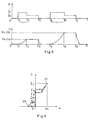
- the electrically controlled variable flow valve according to the present invention is not only constituted by the mechanical parts which have just been described but also comprises a particular device for supplying the direct current electric motor 7 which will be described below. , in relation to the diagrams in Figure 5.
- the supply device sends at an instant t 1 an electric current supplying the motor d intensity I 1 and maintains this current I 1 constant losing a determined duration T a which ends at time t 2 .
- the direct current electric motor 7 rotates at its almost constant nominal speed so as to bring the control piece 3 to an intermediate position for which the tube 2 is partially pinched so that the fluid flow in the tube is carried out according to the flow D wished.
- the supply device abruptly reduces the intensity of the electric current supplying the motor to bring it back to a value I 0 and maintains this intensity I 0 for the entire time during which it is desired to maintain the flow rate fluid flow at constant value D a .
- two intensity levels, I 1 and I 0 , of the motor supply current are therefore used, the first level I 1 being provided for turning the motor to the desired position of opening of the valve and the second level I 0 being provided to keep the engine stationary.
- FIG. 6 Reference will now be made to FIG. 6 to explain how, according to the invention, it is possible to maintain a constant valve opening for any length of time by applying to the electric motor 7 a particular current intensity I 0 . It is first considered that the motor 7 is stopped. If the motor is supplied with electric current at an intensity I which is made to grow slowly, the motor remains blocked, due to the friction of the entire mechanism, until the current intensity reaches a value I x , then starts to rotate all the more quickly as the intensity increases until reaching the speed w 1 corresponding to the intensity I 1 (reference 21 of FIG. 6).
- the motor gradually slows down until it stops for a supply intensity I y , thus remains blocked until the intensity is lowered to the value I z , then begins to rotate in the opposite direction, under the action of the spring 11, until the part 3 comes into abutment.
- the intensities I x and I y are between I 0 and I 1 and the intensity I z is between 0 and I 0 .
- the intensity range between I z and I y causes the motor to stop in all cases. This range results from the fact that the entire mechanism driven by the electric motor 7 offers a certain level of friction which is substantially equal for both directions of motor rotation.
- the intensity I 0 is chosen so as to be in the middle of this range, between the intensities I z and I y , so that this intensity I 0 remains perpetually in the blocking range of the motor even if the friction levels in the mechanism changes slightly over time. If the mechanism were free from any friction, there would be no discontinuity in the curve shown in FIG. 6 which would extend along a substantially straight line between the extreme points 20 and 21 of this curve. In this case, the value I 0 of the intensity for which the motor would turn neither in one direction or the other would be a single value which would not make it possible, in practice to be sure that the engine does not turn. However, as any mechanism of the gear type provides a level of friction which can be determined relatively precisely, it will always be possible, in a real mechanism, to determine a value of the supply intensity I 0 for which the engine locks up regardless of the maneuver performed.
- FIG. 5 two successive actions of controlling the valve are shown, the first being intended to cause the opening of the valve to provide a flow rate of a first chosen value D a and the second a flow rate of one second chosen value D b .
- the supply device likewise supplies two successive sequences, the first providing the high intensity I 1 and the second the lower intensity I 0 .
- the only difference between these two examples of commands lies in the duration of maintenance of the first high intensity I 1 .
- the intensity I 1 To control a first valve opening providing a flow rate of the fluid D a , the intensity I 1 must be maintained for a certain time T a and to obtain an upper valve opening providing a higher flow rate D b , it suffices to maintain the intensity I 1 for a determined upper duration T b . Of course, if you keep it too long the intensity I 1 , the maximum opening of the valve (represented in FIG. 3) is obtained corresponding to the maximum flow.
- FIG. 4 is a diagram illustrating the operation of the device for feeding the motor 7, according to the present invention.
- This supply device essentially comprises a control member 25 maneuverable by the user in order to display the desired flow rate for the valve, a microprocessor 26 and a current generator 27.
- the output signal 28 from the control member 25 is digitized and the numerical values obtained are used in the microprocessor.
- the microprocessor 26 firstly transforms the digital value of the signal from the control member 25 according to a predetermined function so as to provide a signal representative of the angular position that the control piece 3 will have to take to cause the level of pinching of the tube driving the flow rate of the fluid as indicated by the control member 25.
- the microprocessor establishes, as a function of the value of the signal, the duration during which the current generator 27 will have to supply the first intensity d 'supply I 1 , and at the end of which the current generator 27 then supplies the second lower supply intensity I 0 for maintaining the valve in position thus adjusted for the desired flow rate, for any desired duration.
Landscapes
- Engineering & Computer Science (AREA)
- General Engineering & Computer Science (AREA)
- Mechanical Engineering (AREA)
- Electrically Driven Valve-Operating Means (AREA)
Claims (2)
- Flußsteuerventil, das einen Elektromotor (7) aufweist, welcher umkehrbar mit einem Flußeinstellelement (3) in Eingriff steht, das von einer Feder (11) zu einer abgeflachten Position eines elastischen Rohrs bzw. Schlauchs vorgespannt ist, in dem ein Strömungsmittel fließen kann, wobei der Motor (7) derart angeordnet ist, daß er das Einstellelement entgegen der Kraft der Feder (11) bewegt, dadurch gekennzeichnet, daß das Ventil eine Versorgungseinrichtung (26, 27) aufweist, um den Gleichstrommotor während eines sich als eine Funktion der gewünschten Strömung ändernden Zeitintervalls (Ta, Tb) mit einem ersten konstanten Strom (I1) mit einem ausreichenden Wert zum Drehen des Motors zu versorgen, und danach mit einem zweiten konstanten Strom mit einem niedrigeren Wert zu versorgen, wobei der niedrigere Wert ausreichend ist zum Halten des Motors in seiner Lage entgegen der Kraft der Feder.
- Ventil gemäß Anspruch 1, dadurch gekennzeichnet, daß das Ventil in einem Gehäuse (1) ein elastisches Rohr bzw. einen elastischen Schlauch (2) und einen Steuermechanismus zur Gewährleistung eines veränderbaren Abklemmniveaus bzw. -grades des Rohrs (2) aufweist, wobei der Steuermechanismus folgendes aufweist:das Einstellelement (3), das mittels einer schwenkbaren Aufhängung (4) an dem Gehäuse (1) angebracht ist und einen Anlage- bzw. Druckbereich (5), um das Rohr abzuklemmen bzw. abzudrücken, sowie einen gezahnten Abschnitt (6) aufweist, welcher auf der Schwenkachse (4) zentriert ist;ein Zahnrad (10), das in dem Gehäuse drehbar angebracht ist und mit dem gezahnten Abschpitt ein ständig in Eingriff stehendes Getriebe bildet; undden das Zahnrad (10) antreibenden Motor (7).
Applications Claiming Priority (2)
| Application Number | Priority Date | Filing Date | Title |
|---|---|---|---|
| FR9004967 | 1990-04-12 | ||
| FR9004967A FR2660981B1 (fr) | 1990-04-12 | 1990-04-12 | Vanne a debit variable commandee electriquement. |
Publications (2)
| Publication Number | Publication Date |
|---|---|
| EP0452234A1 EP0452234A1 (de) | 1991-10-16 |
| EP0452234B1 true EP0452234B1 (de) | 1996-09-11 |
Family
ID=9395864
Family Applications (1)
| Application Number | Title | Priority Date | Filing Date |
|---|---|---|---|
| EP19910420120 Expired - Lifetime EP0452234B1 (de) | 1990-04-12 | 1991-04-09 | Elektrisch gesteuertes Ventil mit variablem Durchfluss |
Country Status (4)
| Country | Link |
|---|---|
| EP (1) | EP0452234B1 (de) |
| BR (1) | BR9101464A (de) |
| DE (1) | DE69121954T2 (de) |
| FR (1) | FR2660981B1 (de) |
Families Citing this family (5)
| Publication number | Priority date | Publication date | Assignee | Title |
|---|---|---|---|---|
| FR2687446B1 (fr) * | 1992-02-18 | 1995-06-16 | Sextant Avionique | Circuit de commande de vanne. |
| US5413566A (en) * | 1993-03-16 | 1995-05-09 | Micropump Corporation | Line clamp |
| DE19726549C2 (de) * | 1997-06-23 | 1999-08-26 | Walz | Schlauchventil |
| DE102008053998A1 (de) * | 2008-10-30 | 2010-05-06 | Knorr-Bremse Systeme für Nutzfahrzeuge GmbH | Kompressor zur Drucklufterzeugung für ein Kraftfahrzeug |
| DE102019126685B4 (de) * | 2019-10-02 | 2022-12-08 | A. u. K. Müller GmbH & Co KG. | Schlauchventil für Getränkeautomaten |
Family Cites Families (5)
| Publication number | Priority date | Publication date | Assignee | Title |
|---|---|---|---|---|
| FR2331088A1 (fr) * | 1975-11-05 | 1977-06-03 | Clin Midy | Regulateur de debit notamment pour perfusion |
| SE402864B (sv) * | 1976-12-03 | 1978-07-24 | Gambro Ab | Regleranordning for astadkommande av en finreglering respektive en grovreglering |
| DE8335587U1 (de) * | 1983-12-12 | 1987-04-23 | Critikon GmbH, 2000 Norderstedt | Sicherheitseinrichtung mit Stromausfallcharakter für Infusionsregelgeräte |
| US4559036A (en) * | 1983-12-14 | 1985-12-17 | Wunsch Richard E | Apparatus for controlling administration of multiple intravenous solutions and medications |
| NL8802307A (nl) * | 1987-12-17 | 1989-07-17 | Mr W M H Kerbosch B V Handelen | Inrichting voor het regelen van de stroomsnelheid van een infusievloeistof bij een infusiesysteem. |
-
1990
- 1990-04-12 FR FR9004967A patent/FR2660981B1/fr not_active Expired - Fee Related
-
1991
- 1991-04-09 EP EP19910420120 patent/EP0452234B1/de not_active Expired - Lifetime
- 1991-04-09 DE DE1991621954 patent/DE69121954T2/de not_active Expired - Fee Related
- 1991-04-11 BR BR9101464A patent/BR9101464A/pt unknown
Also Published As
| Publication number | Publication date |
|---|---|
| DE69121954T2 (de) | 1997-04-10 |
| DE69121954D1 (de) | 1996-10-17 |
| FR2660981A1 (fr) | 1991-10-18 |
| FR2660981B1 (fr) | 1992-08-14 |
| BR9101464A (pt) | 1991-12-03 |
| EP0452234A1 (de) | 1991-10-16 |
Similar Documents
| Publication | Publication Date | Title |
|---|---|---|
| EP1669648B1 (de) | Motorgesteuertes Ventil | |
| FR2508090A1 (fr) | Dispositif d'entrainement de fil pour moyen de reglage de fenetre | |
| FR2533291A1 (fr) | Procede et dispositif pour commander au moins une section transversale d'etranglement dans une conduite de commande | |
| WO2008055793A1 (fr) | Dispositif de contrôle de l'ouverture ou la fermeture d'une pince dans une pompe volumétrique | |
| EP0452234B1 (de) | Elektrisch gesteuertes Ventil mit variablem Durchfluss | |
| FR2466641A1 (fr) | Pompe peristaltique | |
| FR2837864A1 (fr) | Mecanisme de tension d'un ressort de compensation pour installation de fermeture ou de protection solaire | |
| FR2490712A3 (fr) | Dispositif pour fermer et ouvrir des stores, des volets et des elements pivotants de fenetres en general | |
| FR2503232A1 (fr) | Leve-vitre d'automobile | |
| FR2611549A3 (fr) | Cisaille motorisee auto-alimentee | |
| FR2671582A1 (fr) | Mecanisme de securite pour dispositifs de fermeture a commande electrique du type des volets roulants et similaires. | |
| WO2004059110A1 (fr) | Procede de commande d'une serrure electrique munie d'un embrayage | |
| EP0193466B1 (de) | Elektrische Vorrichtung zum Betätigen der Drosselklappe in einem Innenverbrennungsmotor | |
| FR2756476A1 (fr) | Bouilloire electrique comprenant un recipient dont le debouche est ferme par un couvercle | |
| EP1451840B1 (de) | Handsteuerungseinheit eines schalters | |
| EP0007861B1 (de) | Verstellvorrichtung für einen Rückblickspiegel, insbesondere für Fahrzeuge | |
| FR2655535A1 (fr) | Dispositif de regulation et de controle de l'ecoulement du liquide cephalo-rachidien dans un circuit de drainage externe. | |
| FR2555775A1 (fr) | Dispositif d'actionnement de deux soupapes pouvant etre actionnees en interdependance | |
| FR2701732A1 (fr) | Dispositif ouvre-porte électrique. | |
| EP0318380A1 (de) | Modulierendes Gasversorgungstriebwerk für Brenner einer Vorrichtung in der Art eines Gaskessels | |
| CH645164A5 (fr) | Dispositif de securite pour le raccordement de deux circuits hydrauliques sous pression. | |
| EP0383369B1 (de) | Anordnung bestehend aus einer Drehklappe und einem Antriebsorgan, verbunden durch ein Hebelgestänge | |
| FR2646236A1 (fr) | Dispositif de commande d'ecoulement en volume | |
| CH633073A5 (en) | Device for operating roller shutters and blinds | |
| EP0438936A1 (de) | Einrichtung zum automatischen Rückstellen eines hydraulischen Differentialzylinders |
Legal Events
| Date | Code | Title | Description |
|---|---|---|---|
| PUAI | Public reference made under article 153(3) epc to a published international application that has entered the european phase |
Free format text: ORIGINAL CODE: 0009012 |
|
| AK | Designated contracting states |
Kind code of ref document: A1 Designated state(s): BE CH DE ES GB IT LI NL |
|
| 17P | Request for examination filed |
Effective date: 19920318 |
|
| 17Q | First examination report despatched |
Effective date: 19921015 |
|
| RAP1 | Party data changed (applicant data changed or rights of an application transferred) |
Owner name: CROUZET ELECTROMENAGER |
|
| GRAH | Despatch of communication of intention to grant a patent |
Free format text: ORIGINAL CODE: EPIDOS IGRA |
|
| GRAH | Despatch of communication of intention to grant a patent |
Free format text: ORIGINAL CODE: EPIDOS IGRA |
|
| GRAA | (expected) grant |
Free format text: ORIGINAL CODE: 0009210 |
|
| AK | Designated contracting states |
Kind code of ref document: B1 Designated state(s): BE CH DE ES GB IT LI NL |
|
| PG25 | Lapsed in a contracting state [announced via postgrant information from national office to epo] |
Ref country code: NL Free format text: LAPSE BECAUSE OF FAILURE TO SUBMIT A TRANSLATION OF THE DESCRIPTION OR TO PAY THE FEE WITHIN THE PRESCRIBED TIME-LIMIT Effective date: 19960911 Ref country code: ES Free format text: THE PATENT HAS BEEN ANNULLED BY A DECISION OF A NATIONAL AUTHORITY Effective date: 19960911 |
|
| REG | Reference to a national code |
Ref country code: CH Ref legal event code: NV Representative=s name: MOINAS KIEHL SAVOYE & CRONIN |
|
| REF | Corresponds to: |
Ref document number: 69121954 Country of ref document: DE Date of ref document: 19961017 |
|
| GBT | Gb: translation of ep patent filed (gb section 77(6)(a)/1977) |
Effective date: 19960930 |
|
| ITF | It: translation for a ep patent filed | ||
| NLV1 | Nl: lapsed or annulled due to failure to fulfill the requirements of art. 29p and 29m of the patents act | ||
| PG25 | Lapsed in a contracting state [announced via postgrant information from national office to epo] |
Ref country code: BE Effective date: 19970430 |
|
| PLBE | No opposition filed within time limit |
Free format text: ORIGINAL CODE: 0009261 |
|
| STAA | Information on the status of an ep patent application or granted ep patent |
Free format text: STATUS: NO OPPOSITION FILED WITHIN TIME LIMIT |
|
| 26N | No opposition filed | ||
| BERE | Be: lapsed |
Owner name: CROUZET ELECTROMENAGER Effective date: 19970430 |
|
| PGFP | Annual fee paid to national office [announced via postgrant information from national office to epo] |
Ref country code: GB Payment date: 19990331 Year of fee payment: 9 |
|
| PGFP | Annual fee paid to national office [announced via postgrant information from national office to epo] |
Ref country code: CH Payment date: 19990429 Year of fee payment: 9 |
|
| PGFP | Annual fee paid to national office [announced via postgrant information from national office to epo] |
Ref country code: DE Payment date: 19990430 Year of fee payment: 9 |
|
| PG25 | Lapsed in a contracting state [announced via postgrant information from national office to epo] |
Ref country code: GB Free format text: LAPSE BECAUSE OF NON-PAYMENT OF DUE FEES Effective date: 20000409 |
|
| PG25 | Lapsed in a contracting state [announced via postgrant information from national office to epo] |
Ref country code: LI Free format text: LAPSE BECAUSE OF NON-PAYMENT OF DUE FEES Effective date: 20000430 Ref country code: CH Free format text: LAPSE BECAUSE OF NON-PAYMENT OF DUE FEES Effective date: 20000430 |
|
| GBPC | Gb: european patent ceased through non-payment of renewal fee |
Effective date: 20000409 |
|
| REG | Reference to a national code |
Ref country code: CH Ref legal event code: PL |
|
| PG25 | Lapsed in a contracting state [announced via postgrant information from national office to epo] |
Ref country code: DE Free format text: LAPSE BECAUSE OF NON-PAYMENT OF DUE FEES Effective date: 20010201 |
|
| PG25 | Lapsed in a contracting state [announced via postgrant information from national office to epo] |
Ref country code: IT Free format text: LAPSE BECAUSE OF NON-PAYMENT OF DUE FEES;WARNING: LAPSES OF ITALIAN PATENTS WITH EFFECTIVE DATE BEFORE 2007 MAY HAVE OCCURRED AT ANY TIME BEFORE 2007. THE CORRECT EFFECTIVE DATE MAY BE DIFFERENT FROM THE ONE RECORDED. Effective date: 20050409 |
|
| APAH | Appeal reference modified |
Free format text: ORIGINAL CODE: EPIDOSCREFNO |