EP0452259A2 - Appareil pour produire l'eau chaude sanitaire et procédé pour la marche de l'appareil - Google Patents
Appareil pour produire l'eau chaude sanitaire et procédé pour la marche de l'appareil Download PDFInfo
- Publication number
- EP0452259A2 EP0452259A2 EP91810233A EP91810233A EP0452259A2 EP 0452259 A2 EP0452259 A2 EP 0452259A2 EP 91810233 A EP91810233 A EP 91810233A EP 91810233 A EP91810233 A EP 91810233A EP 0452259 A2 EP0452259 A2 EP 0452259A2
- Authority
- EP
- European Patent Office
- Prior art keywords
- line
- hot water
- heat exchanger
- temperature
- hot
- Prior art date
- Legal status (The legal status is an assumption and is not a legal conclusion. Google has not performed a legal analysis and makes no representation as to the accuracy of the status listed.)
- Granted
Links
Images
Classifications
-
- F—MECHANICAL ENGINEERING; LIGHTING; HEATING; WEAPONS; BLASTING
- F24—HEATING; RANGES; VENTILATING
- F24D—DOMESTIC- OR SPACE-HEATING SYSTEMS, e.g. CENTRAL HEATING SYSTEMS; DOMESTIC HOT-WATER SUPPLY SYSTEMS; ELEMENTS OR COMPONENTS THEREFOR
- F24D17/00—Domestic hot-water supply systems
Definitions
- the invention relates to a device for producing hot domestic water according to the preamble of patent claim 1 and a method for operating the device according to the preamble of patent claim 10.
- the object of the invention is to provide a device for heating domestic water, in which domestic water is heated up as quickly as possible and the hot domestic water drawn off by the consumer has a constant temperature regardless of the amount of hot water required.
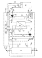
- the device for producing hot domestic water shown in the single figure has a buffer storage 1 with a lower storage connection area for a cold water inlet 3 and an upper storage connection area for a hot water outlet 5.
- the cold water inlet 3 and the hot water outlet 5 are connected to the cold water line 7 and the hot water consumption line 9, respectively e.g. B. connected to a house or hotel.
- a supply line 11 leads from the lower part of the buffer store 1 to a heat exchanger 13 and a hot water outlet line 15 of the heat exchanger 13 opens into the upper part of the buffer store 1 (the hot water outlet line 15 of the heat exchanger 13 is the hot water inlet line of the buffer store 1).
- the hot water outlet 5 is arranged at the highest point of the buffer store 1 and the connection of the hot water outlet line 15 as close as possible to the hot water outlet 5.
- the feed line 11 is connected to the output line 15 via a bypass line 17.
- a three-way valve 19 and between the three-way valve 19 and the connection of the supply line 11 - here designated 11b - a pump 21 is arranged on the heat exchanger 13.
- the three-way valve 19 acts as a shut-off device, with the hot water heated in the heat exchanger 13 the pump 21, depending on the direction of the three-way valve 19, is optionally conveyed in a circuit through the bypass line 17 or into the buffer store 1 or in partial flows through the bypass line 17 and into the buffer store 1, as described below.
- a temperature measuring device 23 is arranged, which is connected to a control device 25 via an electrical signal line 24.
- the electrical signal lines or electrical lines mentioned below are shown in dashed lines to distinguish them from the liquid lines.
- One of the outputs of the control device 25 acts via an electrical line 27 on an actuator 29 which adjusts the three-way valve 19 as described below.
- two further temperature measuring devices 31 and 32 which are arranged in the upper and in the lower half of the buffer store 1, are connected to the control device 25.
- the temperature value measured by the temperature measuring device 31 is compared by the control device 25 with a lower temperature threshold value stored in it and, when the temperature falls below the same, a firing system 34 with a boiler (not shown in more detail) is switched on as a system for heating hot water as a heat-giving fluid via an electrical line 33.
- the firing system 34 is connected to a flow and a return line 35 and 36 with the heat exchanger (heat exchanger) 13.
- a pump 37 is arranged in the flow line 35 and is supplied via an electrical line 39 from the control device 25 is switched on or off.
- the temperature of the hot water in the boiler is measured using a temperature measuring device 41 connected to the control device 25 via a signal line 40.
- the pump 37 is switched on via the electrical line 39.
- the delivery rate of the pump 37 is designed such that a turbulent flow results in the pipes of the heat exchanger 13. In a turbulent flow, optimal heat transfer from the pipe walls to the water flowing in the pipes is guaranteed; the tendency to calcify also decreases.
- the temperature value measured by the temperature measuring devices 32 is compared by the control device 25 with an upper threshold temperature stored in it, and when this is exceeded the pump 37 is switched off via the electrical line 39 and the firing system 34 via the electrical line 33.
- a differential pressure measuring device 42 which is connected to the supply line 11 and the output line 15 and which measures the differential pressure of the heat exchanger 13, is connected to the control device 25 via a signal line 43.
- the flow rate is determined on the basis of the pressure difference of the service water (measured by the differential pressure measuring device 42) between the supply and the outlet lines 11 and 15. If the measured pressure difference exceeds a predetermined value stored in the control device 25, the control device 25 triggers an alarm in an alarm system 45 connected to it by means of an optical and / or acoustic warning signal. An increase in the pressure difference is due to calcification of the heat exchanger 13 possible.
- the alarm represents a request to decalcify the heat exchanger 13.
- a temperature measuring device 49 and 50 is arranged in the supply and return lines 35 and 36, and a hot water flow rate measuring device 51 is arranged in the return line 50.
- the amount of heat absorbed by the heat exchanger 13 is determined from the two temperature values and the flow rate and transferred to the control device 25 via a signal line 52.
- the amount of heat absorbed can be queried periodically by the control device 25 by means of a modem (not shown).
- the buffer store 1, the three-way valve 19, the pumps 21 and 37, the heat exchanger 13, the actuator 29, the temperature measuring devices 23, 31, 32, 49 and 50, the differential pressure measuring device 42, the hot water (boiler water) flow meter 51, the control device 25 , the alarm system 45, the bypass, supply and output lines 17, 11 and 15, the electrical lines 24, 27, 33, 39, 43 and 52 are integrated into a compact, self-contained, transportable finished component 53.
- the finished component 53 delimited in the single figure by a dash-dotted line, has a power connection 54 for the control device 25, the alarm system 45 and the two pumps 21 and 37, as well as the cold water inlet 3, the hot water outlet 5 and a schematically indicated connection 55a and 55b for the flow and return lines 35 and 36 and a connection 55c and 55d for the signal line 40 and the electrical line 33 for switching the firing system 34 containing the boiler on and off.
- the description of the operation of the device begins with a state in which both the domestic water and the hot water are cold.
- the pump 21 is first switched on by the control device 25.
- the control device 25 determines that the temperature measured by the temperature measuring device 23 is below the stored value of the hot water temperature, it closes with the actuator 29 the connection of the part 11a of the supply line 11 to the three-way valve 19, which is directly connected to the lower part of the buffer tank 1 is connected completely and connects the bypass line 17 to the part 11b of the supply line 11 which is connected to the heat exchanger 13.
- the pump 21 thus pumps domestic water in a circuit which contains the bypass line 17 and the heat exchanger 13.
- control device 25 determines that the temperature of the process water in the buffer store 1, measured with the temperature measuring device 31, falls below a lower threshold temperature, and therefore switches the firing system 34 on. As soon as the temperature of the hot water temperature in the boiler measured by the temperature measuring device 41 is greater than the hot water temperature value stored in the control device 25, the pump 37 is switched on via the line 39 by the control device 25 and thus hot water through the supply line 35 into the heat exchanger 13 and from conveyed this back to the boiler via the return line 36. In the heat exchanger 13, heat is now transferred from the hot water to the process water.
- the control device 25 opens the branch of the three-way valve 19 to the line 11a and the branch to the bypass line 17 so far via the actuator 29. that the temperature measured with the temperature measuring device 23 corresponds to the tolerance in the control device 25 stored water temperature value.
- the pump 21 now drives domestic water through the heat exchanger 13, the bypass line 17 and into the buffer store 1.
- the heated domestic water collects in the upper part of the buffer store 1.
- the heating of the process water continues until the process water temperature measured with the temperature measuring device 32 exceeds a value of the upper threshold temperature stored in the control device 25. If this value is exceeded, the control device 25 switches off both pumps 21 and 37 and the furnace in the furnace 34. By switching off the pump 21 it is avoided that heat is removed from the buffer storage 1 when the firing system 34 is switched off by the heat exchanger 13.
- the pump 21 and the three-way valve 19 can also be arranged in the hot water outlet line 15. It is only necessary to ensure that the pump 21 is connected to one of the process water connections of the heat exchanger 13 before any branching of the process water line - with the exception of the connections for the differential pressure measuring device 42. If the pump 21 is in the supply line 11, the pump outlet is and if it is in the hot water outlet line 15, its input is connected to the corresponding connection of the heat exchanger 13.
- the three-way valve 19 can optionally be installed in the supply line 11 or in the hot water outlet line 15 and connected to one of the bypass line ends; a change in the control device 25 is not necessary.
- a thermostatically controllable three-way valve which is not shown, can be used, which is arranged directly from a thermal sensor arranged at the same location as the temperature measuring device 23, which is no longer required is set.
- thermostatic three-way valve 19 instead of the thermostatic three-way valve 19 described above, a thermostatic two-way valve can be used in line part 11a or in part of line 15 leading from bypass line 17 to accumulator 1.
- a throttle device is installed in the bypass part 17 for the purpose of system adjustment.
- the combustion system 34 can be a system with liquid or solid fuels, and an electrical heater can also be used.
- the output line 15 can also be connected to the hot water outlet 5.
- the supply line 11 can also be connected directly to the cold water line 7.
- the device according to the invention for producing hot domestic water has the great advantage that hot domestic water is available for use almost immediately after the supply of heat in the heat exchanger 13, because due to the domestic water circulating completely or partially through the bypass line 17, only a small domestic water volume at the start of heating is heated.
- there is a constant warm service water temperature regardless of the amount of hot water just taken, since the heated service water is supplied to the consumers directly at the outflow of the hot service water already stored in the buffer store 1.
- the operating temperature of the boiler can advantageously be compared to the known hot water treatment plants for the same amount of hot water to be heated, which results in smaller boiler radiation losses. Due to the lowerable temperature for heating the water, waste heat utilization with a lower temperature level than the boiler temperature of conventional boilers can also be used.
- the device according to the invention can be designed in such a way that the burner running time specified by the legislator can be achieved, thus ensuring environmentally friendly combustion and avoiding the so-called "clocking" of the burner.
- the recirculation system on the domestic hot water side enables a wide output range to be covered with only one type of heat exchanger, due to the varying domestic water temperatures when entering the heat exchanger 13.
- a constant heat output is transmitted in the heat exchanger 13 as soon as domestic water is pumped through the pump 21 and 37 hot water through the pump, since on the one hand the volume flows and the temperatures in the domestic and hot water branch are largely constant .
- the temperature in the hot water branch is given by an almost constant supply of energy from the furnace in system 34.
- the dhw temperature is kept essentially constant regardless of the cold water temperature with the three-way valve 19.
Landscapes
- Engineering & Computer Science (AREA)
- Physics & Mathematics (AREA)
- Thermal Sciences (AREA)
- Chemical & Material Sciences (AREA)
- Combustion & Propulsion (AREA)
- Mechanical Engineering (AREA)
- General Engineering & Computer Science (AREA)
- Domestic Hot-Water Supply Systems And Details Of Heating Systems (AREA)
- Domestic Plumbing Installations (AREA)
- Bidet-Like Cleaning Device And Other Flush Toilet Accessories (AREA)
- Massaging Devices (AREA)
- Details Of Fluid Heaters (AREA)
Priority Applications (1)
| Application Number | Priority Date | Filing Date | Title |
|---|---|---|---|
| AT9191810233T ATE105626T1 (de) | 1990-04-02 | 1991-03-28 | Vorrichtung zur erzeugung von warmem brauchwasser und verfahren zum betrieb der vorrichtung. |
Applications Claiming Priority (2)
| Application Number | Priority Date | Filing Date | Title |
|---|---|---|---|
| CH1082/90 | 1990-04-02 | ||
| CH108290 | 1990-04-02 |
Publications (3)
| Publication Number | Publication Date |
|---|---|
| EP0452259A2 true EP0452259A2 (fr) | 1991-10-16 |
| EP0452259A3 EP0452259A3 (en) | 1991-10-23 |
| EP0452259B1 EP0452259B1 (fr) | 1994-05-11 |
Family
ID=4202039
Family Applications (1)
| Application Number | Title | Priority Date | Filing Date |
|---|---|---|---|
| EP91810233A Expired - Lifetime EP0452259B1 (fr) | 1990-04-02 | 1991-03-28 | Appareil pour produire l'eau chaude sanitaire et procédé pour la marche de l'appareil |
Country Status (3)
| Country | Link |
|---|---|
| EP (1) | EP0452259B1 (fr) |
| AT (1) | ATE105626T1 (fr) |
| DE (1) | DE59101593D1 (fr) |
Cited By (1)
| Publication number | Priority date | Publication date | Assignee | Title |
|---|---|---|---|---|
| DE19624551A1 (de) * | 1996-06-20 | 1998-01-02 | Baelz Gmbh Helmut | Verfahren und Vorrichtung zur Brauchwassererwärmung |
Family Cites Families (3)
| Publication number | Priority date | Publication date | Assignee | Title |
|---|---|---|---|---|
| DE3238285A1 (de) * | 1982-10-15 | 1984-04-19 | Max 8491 Katzelsried Bindl Jun. | System zum zufuehren von waermeenergie aus einem aeusseren waermekreislauf an einen brauchwasserkreislauf, insbesondere brauchwasserspeicher |
| DE8812836U1 (de) * | 1988-10-13 | 1990-02-08 | Viessmann Werke GmbH & Co, 3559 Allendorf | Zusatzwärmetauscher |
| FR2647537B1 (fr) * | 1989-05-29 | 1995-04-14 | Chaffoteaux Et Maury | Perfectionnements aux ballons d'eau chaude et aux installations equipees de tels ballons |
-
1991
- 1991-03-28 EP EP91810233A patent/EP0452259B1/fr not_active Expired - Lifetime
- 1991-03-28 AT AT9191810233T patent/ATE105626T1/de not_active IP Right Cessation
- 1991-03-28 DE DE59101593T patent/DE59101593D1/de not_active Expired - Fee Related
Cited By (2)
| Publication number | Priority date | Publication date | Assignee | Title |
|---|---|---|---|---|
| DE19624551A1 (de) * | 1996-06-20 | 1998-01-02 | Baelz Gmbh Helmut | Verfahren und Vorrichtung zur Brauchwassererwärmung |
| DE19624551C2 (de) * | 1996-06-20 | 2002-02-28 | Baelz Gmbh Helmut | Verfahren und Vorrichtung zur Brauchwassererwärmung |
Also Published As
| Publication number | Publication date |
|---|---|
| DE59101593D1 (de) | 1994-06-16 |
| EP0452259B1 (fr) | 1994-05-11 |
| EP0452259A3 (en) | 1991-10-23 |
| ATE105626T1 (de) | 1994-05-15 |
Similar Documents
| Publication | Publication Date | Title |
|---|---|---|
| DE4035115C2 (de) | Anordnung zum aufheizen und zum bereitstellen von warmem oder heissem brauchwasser von trinkwasserqualitaet | |
| DE19511369A1 (de) | Wasserheizanlage zur Bereitung von Brauch- und Heizwasser | |
| EP1170554B1 (fr) | Ensemble et procédé pour préparer de l'eau chaude sanitaire | |
| EP2372260B1 (fr) | Procédé de chauffage d'eau en continu et système de chauffage d'eau | |
| EP0098450A2 (fr) | Source de chaleur chauffée par combustible | |
| EP3800403B1 (fr) | Procédé de fonctionnement d'un dispositif de chauffage, dispositif de chauffage | |
| DE102007048728B4 (de) | Heizkessel, Heizungsanlage sowie Verfahren zum Betreiben einer Heizungsanlage, insbesondere zur solaren Heizungsunterstützung | |
| DE3727442A1 (de) | Verfahren zur erzeugung von warmwasser und vorrichtung zur durchfuehrung dieses verfahrens | |
| DE19508061A1 (de) | Steuerung für eine Durchflußwarmwasserbereitungsanlage | |
| EP0452259B1 (fr) | Appareil pour produire l'eau chaude sanitaire et procédé pour la marche de l'appareil | |
| DE3843376A1 (de) | Aufheizsteuerung eines brauchwasserspeichers | |
| DE2307109A1 (de) | Heizgeraet fuer brauch- und heizwasser | |
| DE3838005C2 (fr) | ||
| DE2217148A1 (de) | Temperatur-regeleinrichtung fuer insbesondere gasbeheizte umlaufwassererhitzer | |
| AT405465B (de) | Wasserheizungsanlage | |
| DE3322612A1 (de) | Brennstoffbeheizte waermequelle | |
| DE4014712C2 (de) | Vorrichtung zum Beheizen von Gebäuden und Anlagen | |
| CH655376A5 (de) | Heizanlage zur warmwasserbereitung. | |
| EP0579933A1 (fr) | Procédé pour le chauffage d'eau sanitaire et chauffé-eau pour la mise en oeuvre du procédé | |
| EP0222040A2 (fr) | Installation de la technique du chauffage | |
| AT527058B1 (de) | Heizvorrichtung und Heizverfahren | |
| EP0111838A2 (fr) | Installation de chauffage des locaux avec plusieurs zones | |
| DE2316349A1 (de) | Verfahren zum regeln der waermeuebertragung in waermetauschern und fuer die anwendung des verfahrens vorgesehener waermetauscher | |
| AT397854B (de) | Verfahren zur steuerung eines kessels | |
| DE102023004787A1 (de) | Hocheffizienter Brauchwassererhitzer im Durchlaufprinzip, welcher mit zwei voneinander unabhängigen Temperaturregelungen ausgerüstet ist, um das zu erhitzende Brauchwasser auf eine exakt voreingestellte Temperatur zu bringen |
Legal Events
| Date | Code | Title | Description |
|---|---|---|---|
| PUAI | Public reference made under article 153(3) epc to a published international application that has entered the european phase |
Free format text: ORIGINAL CODE: 0009012 |
|
| PUAL | Search report despatched |
Free format text: ORIGINAL CODE: 0009013 |
|
| AK | Designated contracting states |
Kind code of ref document: A2 Designated state(s): AT BE CH DE DK ES FR GB IT LI NL SE |
|
| AK | Designated contracting states |
Kind code of ref document: A3 Designated state(s): AT BE CH DE DK ES FR GB IT LI NL SE |
|
| 17P | Request for examination filed |
Effective date: 19920323 |
|
| 17Q | First examination report despatched |
Effective date: 19920731 |
|
| GRAA | (expected) grant |
Free format text: ORIGINAL CODE: 0009210 |
|
| AK | Designated contracting states |
Kind code of ref document: B1 Designated state(s): AT BE CH DE DK ES FR GB IT LI NL SE |
|
| PG25 | Lapsed in a contracting state [announced via postgrant information from national office to epo] |
Ref country code: NL Effective date: 19940511 Ref country code: GB Effective date: 19940511 Ref country code: ES Free format text: THE PATENT HAS BEEN ANNULLED BY A DECISION OF A NATIONAL AUTHORITY Effective date: 19940511 Ref country code: DK Effective date: 19940511 Ref country code: BE Effective date: 19940511 |
|
| REF | Corresponds to: |
Ref document number: 105626 Country of ref document: AT Date of ref document: 19940515 Kind code of ref document: T |
|
| ITF | It: translation for a ep patent filed | ||
| REF | Corresponds to: |
Ref document number: 59101593 Country of ref document: DE Date of ref document: 19940616 |
|
| ET | Fr: translation filed | ||
| NLV1 | Nl: lapsed or annulled due to failure to fulfill the requirements of art. 29p and 29m of the patents act | ||
| GBV | Gb: ep patent (uk) treated as always having been void in accordance with gb section 77(7)/1977 [no translation filed] |
Effective date: 19940511 |
|
| EAL | Se: european patent in force in sweden |
Ref document number: 91810233.6 |
|
| PGFP | Annual fee paid to national office [announced via postgrant information from national office to epo] |
Ref country code: DE Payment date: 19950227 Year of fee payment: 5 |
|
| PGFP | Annual fee paid to national office [announced via postgrant information from national office to epo] |
Ref country code: FR Payment date: 19950315 Year of fee payment: 5 |
|
| PGFP | Annual fee paid to national office [announced via postgrant information from national office to epo] |
Ref country code: SE Payment date: 19950316 Year of fee payment: 5 |
|
| PLBE | No opposition filed within time limit |
Free format text: ORIGINAL CODE: 0009261 |
|
| PGFP | Annual fee paid to national office [announced via postgrant information from national office to epo] |
Ref country code: CH Payment date: 19950322 Year of fee payment: 5 Ref country code: AT Payment date: 19950322 Year of fee payment: 5 |
|
| 26N | No opposition filed | ||
| PG25 | Lapsed in a contracting state [announced via postgrant information from national office to epo] |
Ref country code: AT Effective date: 19960328 |
|
| PG25 | Lapsed in a contracting state [announced via postgrant information from national office to epo] |
Ref country code: SE Effective date: 19960329 |
|
| PG25 | Lapsed in a contracting state [announced via postgrant information from national office to epo] |
Ref country code: LI Effective date: 19960331 Ref country code: CH Effective date: 19960331 |
|
| REG | Reference to a national code |
Ref country code: CH Ref legal event code: PL |
|
| PG25 | Lapsed in a contracting state [announced via postgrant information from national office to epo] |
Ref country code: FR Effective date: 19961129 |
|
| PG25 | Lapsed in a contracting state [announced via postgrant information from national office to epo] |
Ref country code: DE Effective date: 19961203 |
|
| EUG | Se: european patent has lapsed |
Ref document number: 91810233.6 |
|
| REG | Reference to a national code |
Ref country code: FR Ref legal event code: ST |
|
| PG25 | Lapsed in a contracting state [announced via postgrant information from national office to epo] |
Ref country code: IT Free format text: LAPSE BECAUSE OF NON-PAYMENT OF DUE FEES;WARNING: LAPSES OF ITALIAN PATENTS WITH EFFECTIVE DATE BEFORE 2007 MAY HAVE OCCURRED AT ANY TIME BEFORE 2007. THE CORRECT EFFECTIVE DATE MAY BE DIFFERENT FROM THE ONE RECORDED. Effective date: 20050328 |