EP0452272A1 - Accouplement élastique - Google Patents
Accouplement élastique Download PDFInfo
- Publication number
- EP0452272A1 EP0452272A1 EP91810253A EP91810253A EP0452272A1 EP 0452272 A1 EP0452272 A1 EP 0452272A1 EP 91810253 A EP91810253 A EP 91810253A EP 91810253 A EP91810253 A EP 91810253A EP 0452272 A1 EP0452272 A1 EP 0452272A1
- Authority
- EP
- European Patent Office
- Prior art keywords
- drive part
- coupling
- coupling elements
- parts
- circumferential direction
- Prior art date
- Legal status (The legal status is an assumption and is not a legal conclusion. Google has not performed a legal analysis and makes no representation as to the accuracy of the status listed.)
- Granted
Links
Images

Classifications
-
- F—MECHANICAL ENGINEERING; LIGHTING; HEATING; WEAPONS; BLASTING
- F16—ENGINEERING ELEMENTS AND UNITS; GENERAL MEASURES FOR PRODUCING AND MAINTAINING EFFECTIVE FUNCTIONING OF MACHINES OR INSTALLATIONS; THERMAL INSULATION IN GENERAL
- F16H—GEARING
- F16H55/00—Elements with teeth or friction surfaces for conveying motion; Worms, pulleys or sheaves for gearing mechanisms
- F16H55/02—Toothed members; Worms
- F16H55/14—Construction providing resilience or vibration-damping
-
- F—MECHANICAL ENGINEERING; LIGHTING; HEATING; WEAPONS; BLASTING
- F16—ENGINEERING ELEMENTS AND UNITS; GENERAL MEASURES FOR PRODUCING AND MAINTAINING EFFECTIVE FUNCTIONING OF MACHINES OR INSTALLATIONS; THERMAL INSULATION IN GENERAL
- F16D—COUPLINGS FOR TRANSMITTING ROTATION; CLUTCHES; BRAKES
- F16D3/00—Yielding couplings, i.e. with means permitting movement between the connected parts during the drive
- F16D3/50—Yielding couplings, i.e. with means permitting movement between the connected parts during the drive with the coupling parts connected by one or more intermediate members
- F16D3/56—Yielding couplings, i.e. with means permitting movement between the connected parts during the drive with the coupling parts connected by one or more intermediate members comprising elastic metal lamellae, elastic rods, or the like, e.g. arranged radially or parallel to the axis, the members being shear-loaded collectively by the total load
- F16D3/58—Yielding couplings, i.e. with means permitting movement between the connected parts during the drive with the coupling parts connected by one or more intermediate members comprising elastic metal lamellae, elastic rods, or the like, e.g. arranged radially or parallel to the axis, the members being shear-loaded collectively by the total load the intermediate members being made of rubber or like material
-
- F—MECHANICAL ENGINEERING; LIGHTING; HEATING; WEAPONS; BLASTING
- F16—ENGINEERING ELEMENTS AND UNITS; GENERAL MEASURES FOR PRODUCING AND MAINTAINING EFFECTIVE FUNCTIONING OF MACHINES OR INSTALLATIONS; THERMAL INSULATION IN GENERAL
- F16D—COUPLINGS FOR TRANSMITTING ROTATION; CLUTCHES; BRAKES
- F16D3/00—Yielding couplings, i.e. with means permitting movement between the connected parts during the drive
- F16D3/50—Yielding couplings, i.e. with means permitting movement between the connected parts during the drive with the coupling parts connected by one or more intermediate members
- F16D3/70—Yielding couplings, i.e. with means permitting movement between the connected parts during the drive with the coupling parts connected by one or more intermediate members comprising elastic elements arranged in holes in one coupling part and surrounding pins on the other coupling part
Definitions
- the invention relates to an elastic coupling with an inner drive part which can be attached to a shaft and an outer drive part which is movably mounted on the shaft in the circumferential direction, and with a plurality of coupling elements which are offset in the circumferential direction and which have the one, first drive part with two arranged on both sides and the other, Connect second drive part attachable ring disk-like wall parts and each contain an elastically deformable spring body arranged between two holders.
- a coupling is known, the inner drive part of which is formed by a plurality of spoke-like projections projecting radially from a hub section, while the outer drive part is a ring section which can be placed on these projections and is arranged tooth-like inward over its inner circumference protruding projections which can be inserted into the gaps formed between the projections of the inner drive part.
- the projections of the outer drive part are each flexibly connected to the adjacent projections of the inner drive part in the circumferential direction via two coupling elements which can be pressed onto their end faces on both sides.
- the Coupling elements of this known design each consist of two approximately trapezoidal support plates and an elastically deformable rubber body vulcanized between them, one support plate each being clampable against the relevant end face of the projection of the outer drive part and the second support plate the between the projections adjacent in both circumferential directions inner drive part formed gap is bridged and attached to the corresponding end faces of these projections of the inner drive part.
- the known design with the interlocking projections of the two drive parts requires a relatively large outlay in the production of these relatively highly loaded drive parts and in the installation of the coupling elements connecting them, which in addition to the forces acting in the circumferential direction also absorb the transverse forces introduced via the ring gear have to. Accordingly, undesirable misalignments can occur for the tooth engagement. Due to the design dimensions of the interlocking projections, a relatively small number of these coupling elements is also determined, so that the individual coupling elements are stressed relatively high.
- the inner drive part and the outer drive part interact via spherical bearing surfaces, by means of which the outer drive part carrying a ring gear should be adjustable in relation to the hub in the circumferential direction and at right angles thereto.
- the wall parts designed as driving disks on the inner drive part are each arranged at an axial distance from the hub part of the outer drive part mounted on the inner drive part, so that the latter is perpendicular to the circumferential direction can adjust freely.
- the coupling elements are not only loaded by the driving and braking forces acting in both circumferential directions, but also additionally by the transverse forces acting in the axial direction.
- the coupling arrangement of this known embodiment which allows the toothed ring to deflect laterally, is therefore not suitable for absorbing larger transverse forces, such as occur, for example, when using toothed rings provided with helical teeth.
- the invention has for its object to provide a particularly improved in this regard, universally applicable coupling of the type mentioned, in a simplified, lighter design, which allows easier installation and removal of coupling elements which are cheaper than previous designs.
- the two drive parts are each designed with cylindrical bearing surfaces running essentially over the entire outer or inner circumference, and in that the first drive part is designed with shoulder parts which can be placed on both sides of the wall parts and are intended for transmitting transverse forces .
- the coupling designed according to the invention consists of parts that are easy to manufacture, for the most part turned parts, the assembly of which requires a relatively small amount of work. Due to the cylindrical bearing surfaces of the two drive parts that are free of local inner protrusions, especially in comparison to designs with spoke-like protrusions, there is advantageously less stress on the surface pressure of the interacting parts Drive parts and a significant reduction in unsprung masses can be achieved. At the same time, the support parts that can be attached to the wall parts ensure a clear transverse guidance of the outer drive part and thus avoid additional stress on the coupling elements due to transverse forces.
- the clutch arrangement according to the invention is therefore also suitable for designs with helical toothed gears.
- the coupling according to FIGS. 1 and 2 is contained in a drive device of a rail vehicle, which is only partially shown and which is intended for transmitting the torque of a motor, not shown, to a wheel set axle, according to the illustration a shaft 1, of the rail vehicle.
- This drive device has an inner drive part 2, which is connected in a rotationally fixed manner to the shaft 1, and an outer drive part 3 surrounding the latter, which is flexibly coupled in the circumferential direction to the inner drive part 2 by means of resilient coupling elements 4 arranged offset in the circumferential direction.
- the inner drive part 2 contains a hub section 5, an inner wall section 7 projecting outwardly from this in a ring shape and a flange section 8 surrounding the latter, which with the wall section 7, seen in axial section, delimits a T-shaped cross section and which is continuous over its entire circumference Bearing surface 9 for the outer drive part 3 forms.
- the outer drive part 3 contains an annular crown section 10, which is mounted such that it can move in the circumferential direction with a bearing surface 9a on the flange section 8, and two driver parts projecting towards the shaft 1 in the form of two annular disk-like wall parts 11, which are on both sides of the inner drive part 2, on shoulder parts 39 of the flange section 8 can be put on, arranged and fastened to the ring section 10 by screws 12 arranged distributed along their outer circumference.
- the crown section 10 on the flange section 8 is held immovably in the axial direction by the wall parts 11.
- the wreath section 10 is provided with a toothing 13 which for Intervention in a gear, for example a pinion (not shown) of the drive motor of the rail vehicle, is determined.
- the toothing 13 can be designed as a helical toothing, the corresponding transverse forces introduced via the crown section 10 being transmitted directly via the wall parts 11 to the inner drive part 2 and from there to the shaft 1.
- the coupling elements 4 are therefore not stressed by these transverse forces.
- the coupling elements 4 are arranged in pairs on both sides of the wall section 7 and are each connected to two opposite sections in the axial direction of the shaft 1 of the end faces of the wall section 7 and one of the wall parts 11 that run transversely, as shown perpendicularly to the axis A of the shaft 1.
- the coupling elements 4 each contain a cylindrical spring body 15 made of an elastically deformable, rubber-like material, which is held between two holders 14 and 16, for example glued or vulcanized.
- the holders 14 and 16 are each designed with a circular support plate which can be placed on the wall section 7 or the relevant wall part 11 and a guide pin 17 projecting outwards therefrom.
- the wall section 7 and the wall parts 11 are each designed with bores 18 which are offset in the circumferential direction and run parallel to the axis A of the shaft 1 and which receive these guide pins 17.
- the two wall parts 11 are held in their inner circumferential areas against one another and / or — via the coupling elements 4 — against the wall section 7 by screws 20 arranged parallel to the axis A.
- the screws 20 are arranged in spacers, as shown support tubes 21, which each penetrate a passage opening 22 provided in the wall section 7.
- the passage openings 22 are each designed with a diameter that allows unhindered relative movements of the wall parts 11 connected support tubes 21 in both circumferential directions, corresponding to a predetermined, maximum possible spring travel of the spring body 15 in question, and which on the other hand can limit these relative movements to a dimension corresponding to a permissible thrust path of the spring body 15.
- the wall parts 11 can be braced against one another and against the wall part 7 up to a distance given by the length of the support tubes 21, a cage-like holder for the coupling elements 4 being formed from easily producible parts.
- the wall parts 11 each held in the outer and in the inner peripheral region can be designed with relatively small wall thicknesses, which enable a relatively slim design of the coupling.
- the easily producible coupling elements 4 can be inserted loosely into the holder, exchanged with little effort and can be held in a simple manner under a precisely adjustable preload.
- the coupling elements 4, which are essentially unloaded by transverse forces, can be designed with a relatively low transverse rigidity and thus require a relatively low preload.
- the arrangement described also enables the installation of a relatively large number of coupling elements 4, which can each be designed with a relatively low shear stiffness in the circumferential direction, since the sum of the shear stiffnesses of the individual coupling elements 4 results in a sufficient overall stiffness of all coupling elements 4. It has been shown that in a rail vehicle with a coupling designed in the manner described, the entirety of the coupling elements 4 has an essentially linear spring constant over the entire range of the tensile force to be transmitted, in particular the starting tractive force of the rail vehicle the stress on the individual spring bodies 15 can be kept relatively small.
- the bearing surface 9 formed by the flange section 8 and extending over its entire circumference permits precise guidance of the ring section 10, whereby - in particular in comparison to versions with a ring section mounted on spoke-like support sections - a significantly reduced stress on surface pressure and improved lubrication of the sliding parts is achieved. At the same time, deformation of the crown section 10 supported over its entire inner circumference is avoided.
- annular inner drive part 25 is coupled to an outer drive part 26, which contains a hub part 27 movably mounted on the drive part 25 in the circumferential direction, a wall part 28 projecting radially therefrom and a flange part 30 on which the toothing 13 is formed.
- the hub portion 27 is guided with its lateral shoulder portions 30 between two annular disk-like wall parts 11a, which are fastened with their inner peripheral parts to the inner drive part 25 and with their outer peripheral regions protruding from the flange portion 30 via the support tubes 21 against one another and / or via the coupling elements 4 against the Wall section 28 are braced.
- This design results in a clutch in a compact, space-saving design, which is particularly suitable for the formation of a drive gear with a relatively small diameter.
- the precisely machined bearing surfaces 9 and 9a are designed with a smaller diameter and are therefore correspondingly easier to manufacture than with the coupling according to FIGS. 1 and 2.
- the design according to FIGS Figures 3 and 4 the coupling elements 4 are arranged at a greater radial distance from the axis A and thus, for example, each with a larger diameter and / or designed for correspondingly smaller peripheral forces.
- the spring body 15 of the coupling elements 4 are essentially subjected to thrust.
- the crown section 10 of an outer drive part 32 can be mounted on an approximately ring-shaped inner drive part 31 and can be coupled to the latter via two annular disk-like wall parts 33 and via cylindrical coupling elements 34 arranged parallel to the axis A and offset in the circumferential direction essentially have spring bodies 36 made of rubber or a corresponding, elastically deformable material that are subjected to pressure.
- the spring bodies 36 are tubular and are each fastened, for example vulcanized, between two holders 35 and 37 in the form of concentrically arranged pipe sections.
- the coupling elements 34 are inserted, for example pressed, with their outer holders 37 in a through bore 38 of the inner drive part 31 parallel to the axis A.
- the outer holder 37 and the spring body 36 are held at a distance from the wall parts 33, each of which forms a lateral guide for the shoulder part 39 of the drive part 31 and which by means of the screws 20 via the inner holder receiving these, projecting from the spring bodies 36 on both sides 35 are braced.
- the ends of the inner holders 35 can each protrude into a recess 40 formed on the relevant wall part 33, in which the relevant end is held fixed in the circumferential direction.
- This embodiment results in a clutch with a relatively small spring travel of the clutch elements 34 in a significantly simplified manner compared to the embodiments according to FIGS. 1 to 4 Construction, which is particularly suitable for applications that require a relatively hard suspension in the circumferential direction.
- corresponding coupling elements 34 can be arranged in bores 38 of an outer drive part 42 which is supported with a hub part 43 on an annular inner drive part 41 fastened on the shaft 1.
- the hub portion 43 is guided with its shoulder portions 39 between two annular disk-like wall parts 33a, which are fastened with their inner circumferential parts to the inner drive part 41 and can be braced against one another with their free circumferential parts via the inner holders 35 of the coupling elements 34.
- the coupling elements 34 can be arranged on a larger pitch circle and thus designed for correspondingly lower circumferential forces and / or can each be designed with a relatively large outside diameter.
- the bearing surfaces 9 and 9a to be precisely machined are designed with a smaller diameter and are therefore correspondingly easier to manufacture than with the coupling according to FIG. 5.
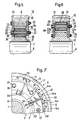
- the coupling according to FIG. 7 contains coupling elements 4a which can be placed close together in the circumferential direction, with support plates 16a and spring bodies 15 arranged between them, which, as shown, can be designed in the form of congruent ring disk segments.
- This embodiment allows a substantially gap-free covering of the two installation areas for the loosely usable coupling elements 4a which can be preloaded by means of the screws 20.
- Corresponding coupling elements can also be used in other, e.g. be trapezoidal, shapes that result in an annular arrangement with polygonal inner and / or outer circumference.
Landscapes
- Engineering & Computer Science (AREA)
- General Engineering & Computer Science (AREA)
- Mechanical Engineering (AREA)
- Mechanical Operated Clutches (AREA)
- Radiation-Therapy Devices (AREA)
- Friction Gearing (AREA)
Applications Claiming Priority (2)
| Application Number | Priority Date | Filing Date | Title |
|---|---|---|---|
| CH1213/90 | 1990-04-10 | ||
| CH121390 | 1990-04-10 |
Publications (2)
| Publication Number | Publication Date |
|---|---|
| EP0452272A1 true EP0452272A1 (fr) | 1991-10-16 |
| EP0452272B1 EP0452272B1 (fr) | 1995-04-05 |
Family
ID=4205153
Family Applications (1)
| Application Number | Title | Priority Date | Filing Date |
|---|---|---|---|
| EP91810253A Expired - Lifetime EP0452272B1 (fr) | 1990-04-10 | 1991-04-05 | Accouplement élastique |
Country Status (3)
| Country | Link |
|---|---|
| EP (1) | EP0452272B1 (fr) |
| AT (1) | ATE120837T1 (fr) |
| DE (1) | DE59105072D1 (fr) |
Cited By (3)
| Publication number | Priority date | Publication date | Assignee | Title |
|---|---|---|---|---|
| CN104110444A (zh) * | 2013-04-18 | 2014-10-22 | 兰州二建集团建鑫工程有限公司 | 一种多功能限位器的柔性联接装置 |
| FR3036153A1 (fr) * | 2015-05-12 | 2016-11-18 | Messier Bugatti Dowty | Galet d'entrainement. |
| WO2025190450A1 (fr) | 2024-03-14 | 2025-09-18 | Schaeffler Technologies AG & Co. KG | Module de moyeu de roue |
Citations (11)
| Publication number | Priority date | Publication date | Assignee | Title |
|---|---|---|---|---|
| CH108989A (de) * | 1924-01-12 | 1925-02-16 | Maag Zahnraeder & Maschinen A | Zahnrad mit auf einem Radkörper drehbarem und federnd mit diesem verbundenen Zahnkranz. |
| GB504582A (en) * | 1937-02-04 | 1939-04-27 | Firestone Tire & Rubber Co | Improvements in or relating to resilient couplings for transmitting rotary motion |
| FR843965A (fr) * | 1938-03-19 | 1939-07-13 | Bromsregulator Svenska Ab | Accouplement élastique |
| DE850097C (de) * | 1951-04-15 | 1952-09-22 | Deutsche Bundesbahn | Gefedertes Zahnrad mit beliebiger Verzahnung |
| US2659244A (en) * | 1949-09-16 | 1953-11-17 | U S Universal Joints Company | Combined resilient coupling and vibration dampener |
| DE1012129B (de) * | 1954-07-09 | 1957-07-11 | Eisenwerke Muelheim Meiderich | Zahnrad mit gefedertem Zahnkranz |
| DE1038086B (de) * | 1954-04-07 | 1958-09-04 | Licentia Gmbh | Grossrad fuer Bahnantrieb mit gegen die Nabe elastisch abgefedertem Zahnkranz |
| CH378604A (de) * | 1960-04-30 | 1964-06-15 | Schweizerische Lokomotiv | In Dreh- und Axialrichtung elastisch nachgiebige Wellenkupplung |
| GB1173434A (en) * | 1966-10-11 | 1969-12-10 | Brown Gear Ind | Resilient or Shock Absorbing Wheels |
| CH600188A5 (fr) * | 1976-02-20 | 1978-06-15 | Bbc Brown Boveri & Cie | |
| GB2073370A (en) * | 1980-03-29 | 1981-10-14 | Hackforth Gmbh & Co Kg | Resilient shaft couplings |
-
1991
- 1991-04-05 DE DE59105072T patent/DE59105072D1/de not_active Expired - Lifetime
- 1991-04-05 EP EP91810253A patent/EP0452272B1/fr not_active Expired - Lifetime
- 1991-04-05 AT AT91810253T patent/ATE120837T1/de not_active IP Right Cessation
Patent Citations (11)
| Publication number | Priority date | Publication date | Assignee | Title |
|---|---|---|---|---|
| CH108989A (de) * | 1924-01-12 | 1925-02-16 | Maag Zahnraeder & Maschinen A | Zahnrad mit auf einem Radkörper drehbarem und federnd mit diesem verbundenen Zahnkranz. |
| GB504582A (en) * | 1937-02-04 | 1939-04-27 | Firestone Tire & Rubber Co | Improvements in or relating to resilient couplings for transmitting rotary motion |
| FR843965A (fr) * | 1938-03-19 | 1939-07-13 | Bromsregulator Svenska Ab | Accouplement élastique |
| US2659244A (en) * | 1949-09-16 | 1953-11-17 | U S Universal Joints Company | Combined resilient coupling and vibration dampener |
| DE850097C (de) * | 1951-04-15 | 1952-09-22 | Deutsche Bundesbahn | Gefedertes Zahnrad mit beliebiger Verzahnung |
| DE1038086B (de) * | 1954-04-07 | 1958-09-04 | Licentia Gmbh | Grossrad fuer Bahnantrieb mit gegen die Nabe elastisch abgefedertem Zahnkranz |
| DE1012129B (de) * | 1954-07-09 | 1957-07-11 | Eisenwerke Muelheim Meiderich | Zahnrad mit gefedertem Zahnkranz |
| CH378604A (de) * | 1960-04-30 | 1964-06-15 | Schweizerische Lokomotiv | In Dreh- und Axialrichtung elastisch nachgiebige Wellenkupplung |
| GB1173434A (en) * | 1966-10-11 | 1969-12-10 | Brown Gear Ind | Resilient or Shock Absorbing Wheels |
| CH600188A5 (fr) * | 1976-02-20 | 1978-06-15 | Bbc Brown Boveri & Cie | |
| GB2073370A (en) * | 1980-03-29 | 1981-10-14 | Hackforth Gmbh & Co Kg | Resilient shaft couplings |
Cited By (7)
| Publication number | Priority date | Publication date | Assignee | Title |
|---|---|---|---|---|
| CN104110444A (zh) * | 2013-04-18 | 2014-10-22 | 兰州二建集团建鑫工程有限公司 | 一种多功能限位器的柔性联接装置 |
| FR3036153A1 (fr) * | 2015-05-12 | 2016-11-18 | Messier Bugatti Dowty | Galet d'entrainement. |
| CN106143879A (zh) * | 2015-05-12 | 2016-11-23 | 梅西耶-布加蒂-道提公司 | 驱动辊 |
| EP3093528A3 (fr) * | 2015-05-12 | 2017-03-22 | Safran Landing Systems | Galet d'entrainement |
| CN106143879B (zh) * | 2015-05-12 | 2018-09-11 | 梅西耶-布加蒂-道提公司 | 驱动辊 |
| WO2025190450A1 (fr) | 2024-03-14 | 2025-09-18 | Schaeffler Technologies AG & Co. KG | Module de moyeu de roue |
| DE102024107228A1 (de) * | 2024-03-14 | 2025-09-18 | Schaeffler Technologies AG & Co. KG | Rad-Naben-Modul |
Also Published As
| Publication number | Publication date |
|---|---|
| ATE120837T1 (de) | 1995-04-15 |
| EP0452272B1 (fr) | 1995-04-05 |
| DE59105072D1 (de) | 1995-05-11 |
Similar Documents
| Publication | Publication Date | Title |
|---|---|---|
| DE69615770T2 (de) | Rotierender Träger mit Bremsscheiben, insbesondere zur Benutzung in Eisenbahnen | |
| DE3150800A1 (de) | Radial verformbares lager und torsionsdaempfungsvorrichtung, insbesondere reibkupplung fuer kraftfahrzeuge mit einem solchen lager | |
| DE69101404T2 (de) | Torsionsdämpfende Vorrichtung für Reibplatte einer Kraftfahrzeugkupplung. | |
| DE2657575C3 (de) | Parallelwellenantrieb | |
| DE3920588C5 (de) | Drehschwingungsdämpfer, insbesondere für die Kupplungsscheibe eines Kraftfahrzeuges | |
| EP0219683B1 (fr) | Dispositif d'étanchéité | |
| DE102019125310A1 (de) | Planetenwälzgetriebe | |
| DE3428764A1 (de) | Zahnrad, insbesondere fuer kettenfahrzeuge | |
| DE4418284A1 (de) | Drehschwingungsdämpfer-Doppelschwungrad, insbesondere für Kraftfahrzeuge | |
| DE3843496C1 (fr) | ||
| EP0801241B1 (fr) | Accouplement élastique permettant un mouvement axial et angulaire | |
| EP0103825B1 (fr) | Accouplement élastique | |
| DE2916254C2 (fr) | ||
| EP0452272B1 (fr) | Accouplement élastique | |
| EP0632210B1 (fr) | Accouplement à dents, notamment pour unité de traction d'une véhicule ferroviaire | |
| DE69613198T2 (de) | Drehschwingungsdämpfer,insbesondere für Kraftfahrzeuge | |
| DE3823745C2 (de) | Schwungscheibe mit Schwingungsdämpfer | |
| DE69610890T2 (de) | Trockenreibungskupplung für Kraftfahrzeuge | |
| DE3406054A1 (de) | Torsionsdaempfungsvorrichtung insbesondere reibungskupplung, insbesondere fuer kraftfahrzeuge | |
| DE2853839A1 (de) | Doppelachsantrieb fuer drehgestelle von schienenfahrzeugen | |
| DE4137234A1 (de) | Antriebseinheit fuer schienentriebfahrzeuge | |
| EP0425769B1 (fr) | Accouplement élastique pour transmission de couple | |
| DE4137233C2 (de) | Antriebseinheit für Schienentriebfahrzeuge | |
| EP0172922B1 (fr) | Roue dentée, en particulier pour véhicules à chenille | |
| DE8815843U1 (de) | Reibungskupplung oder -bremse mit Dämpfungselement |
Legal Events
| Date | Code | Title | Description |
|---|---|---|---|
| PUAI | Public reference made under article 153(3) epc to a published international application that has entered the european phase |
Free format text: ORIGINAL CODE: 0009012 |
|
| AK | Designated contracting states |
Kind code of ref document: A1 Designated state(s): AT CH DE FR GB IT LI SE |
|
| 17P | Request for examination filed |
Effective date: 19920403 |
|
| 17Q | First examination report despatched |
Effective date: 19930820 |
|
| RAP1 | Party data changed (applicant data changed or rights of an application transferred) |
Owner name: SLM SCHWEIZERISCHE LOKOMOTIV- UND MASCHINENFABRIK |
|
| GRAA | (expected) grant |
Free format text: ORIGINAL CODE: 0009210 |
|
| AK | Designated contracting states |
Kind code of ref document: B1 Designated state(s): AT CH DE FR GB IT LI SE |
|
| REF | Corresponds to: |
Ref document number: 120837 Country of ref document: AT Date of ref document: 19950415 Kind code of ref document: T |
|
| GBT | Gb: translation of ep patent filed (gb section 77(6)(a)/1977) |
Effective date: 19950403 |
|
| REF | Corresponds to: |
Ref document number: 59105072 Country of ref document: DE Date of ref document: 19950511 |
|
| ET | Fr: translation filed | ||
| ITF | It: translation for a ep patent filed | ||
| PLBE | No opposition filed within time limit |
Free format text: ORIGINAL CODE: 0009261 |
|
| 26N | No opposition filed | ||
| PGFP | Annual fee paid to national office [announced via postgrant information from national office to epo] |
Ref country code: FR Payment date: 19990324 Year of fee payment: 9 |
|
| PG25 | Lapsed in a contracting state [announced via postgrant information from national office to epo] |
Ref country code: FR Free format text: LAPSE BECAUSE OF NON-PAYMENT OF DUE FEES Effective date: 20001229 |
|
| REG | Reference to a national code |
Ref country code: FR Ref legal event code: ST |
|
| REG | Reference to a national code |
Ref country code: CH Ref legal event code: NV Representative=s name: ROTTMANN, ZIMMERMANN + PARTNER AG Ref country code: CH Ref legal event code: PUE Owner name: SLM SCHWEIZERISCHE LOKOMOTIV- UND MASCHINENFABRIK |
|
| REG | Reference to a national code |
Ref country code: GB Ref legal event code: IF02 |
|
| PGFP | Annual fee paid to national office [announced via postgrant information from national office to epo] |
Ref country code: GB Payment date: 20030415 Year of fee payment: 13 |
|
| PGFP | Annual fee paid to national office [announced via postgrant information from national office to epo] |
Ref country code: SE Payment date: 20030417 Year of fee payment: 13 |
|
| PG25 | Lapsed in a contracting state [announced via postgrant information from national office to epo] |
Ref country code: GB Free format text: LAPSE BECAUSE OF NON-PAYMENT OF DUE FEES Effective date: 20040405 |
|
| PG25 | Lapsed in a contracting state [announced via postgrant information from national office to epo] |
Ref country code: SE Free format text: LAPSE BECAUSE OF NON-PAYMENT OF DUE FEES Effective date: 20040406 |
|
| GBPC | Gb: european patent ceased through non-payment of renewal fee | ||
| EUG | Se: european patent has lapsed | ||
| PGFP | Annual fee paid to national office [announced via postgrant information from national office to epo] |
Ref country code: IT Payment date: 20100426 Year of fee payment: 20 Ref country code: DE Payment date: 20100423 Year of fee payment: 20 Ref country code: AT Payment date: 20100415 Year of fee payment: 20 |
|
| PGFP | Annual fee paid to national office [announced via postgrant information from national office to epo] |
Ref country code: CH Payment date: 20100423 Year of fee payment: 20 |
|
| REG | Reference to a national code |
Ref country code: DE Ref legal event code: R071 Ref document number: 59105072 Country of ref document: DE |
|
| REG | Reference to a national code |
Ref country code: CH Ref legal event code: PL |
|
| PG25 | Lapsed in a contracting state [announced via postgrant information from national office to epo] |
Ref country code: DE Free format text: LAPSE BECAUSE OF EXPIRATION OF PROTECTION Effective date: 20110405 |