EP0452308B1 - Echantillonneur integre pour eprouvettes fermees et ouvertes - Google Patents
Echantillonneur integre pour eprouvettes fermees et ouvertes Download PDFInfo
- Publication number
- EP0452308B1 EP0452308B1 EP89903018A EP89903018A EP0452308B1 EP 0452308 B1 EP0452308 B1 EP 0452308B1 EP 89903018 A EP89903018 A EP 89903018A EP 89903018 A EP89903018 A EP 89903018A EP 0452308 B1 EP0452308 B1 EP 0452308B1
- Authority
- EP
- European Patent Office
- Prior art keywords
- sample liquid
- sample
- closed
- containers
- liquid
- Prior art date
- Legal status (The legal status is an assumption and is not a legal conclusion. Google has not performed a legal analysis and makes no representation as to the accuracy of the status listed.)
- Expired - Lifetime
Links
- 239000000523 sample Substances 0.000 claims abstract description 596
- 239000007788 liquid Substances 0.000 claims abstract description 450
- 238000005070 sampling Methods 0.000 claims abstract description 159
- 238000004458 analytical method Methods 0.000 claims abstract description 61
- 238000002955 isolation Methods 0.000 claims abstract description 36
- 238000000034 method Methods 0.000 claims abstract description 36
- 230000002209 hydrophobic effect Effects 0.000 claims abstract description 15
- 239000004094 surface-active agent Substances 0.000 claims abstract description 15
- 239000002245 particle Substances 0.000 claims abstract description 12
- 230000007717 exclusion Effects 0.000 claims abstract description 8
- 238000011109 contamination Methods 0.000 claims description 14
- 230000009471 action Effects 0.000 claims description 5
- 230000035515 penetration Effects 0.000 claims description 5
- 230000005661 hydrophobic surface Effects 0.000 claims description 3
- 239000011248 coating agent Substances 0.000 claims 2
- 238000000576 coating method Methods 0.000 claims 2
- 230000003247 decreasing effect Effects 0.000 claims 2
- 238000011067 equilibration Methods 0.000 description 15
- 239000002699 waste material Substances 0.000 description 8
- 230000008901 benefit Effects 0.000 description 7
- 238000010586 diagram Methods 0.000 description 6
- 238000001704 evaporation Methods 0.000 description 6
- 230000008020 evaporation Effects 0.000 description 6
- 239000004033 plastic Substances 0.000 description 6
- 229920003023 plastic Polymers 0.000 description 6
- 239000012530 fluid Substances 0.000 description 5
- 238000003780 insertion Methods 0.000 description 5
- 230000037431 insertion Effects 0.000 description 5
- 238000011068 loading method Methods 0.000 description 5
- 239000003570 air Substances 0.000 description 4
- 239000012080 ambient air Substances 0.000 description 4
- 230000002572 peristaltic effect Effects 0.000 description 4
- 239000007787 solid Substances 0.000 description 4
- 230000004913 activation Effects 0.000 description 3
- 238000001514 detection method Methods 0.000 description 3
- 238000001914 filtration Methods 0.000 description 3
- 229930195733 hydrocarbon Natural products 0.000 description 3
- 150000002430 hydrocarbons Chemical class 0.000 description 3
- 239000000463 material Substances 0.000 description 3
- 239000000203 mixture Substances 0.000 description 3
- 238000005086 pumping Methods 0.000 description 3
- 239000004809 Teflon Substances 0.000 description 2
- 229920006362 Teflon® Polymers 0.000 description 2
- 230000005540 biological transmission Effects 0.000 description 2
- 230000015556 catabolic process Effects 0.000 description 2
- 238000004891 communication Methods 0.000 description 2
- 238000006731 degradation reaction Methods 0.000 description 2
- 238000011049 filling Methods 0.000 description 2
- 239000011521 glass Substances 0.000 description 2
- 230000002401 inhibitory effect Effects 0.000 description 2
- 238000002347 injection Methods 0.000 description 2
- 239000007924 injection Substances 0.000 description 2
- 230000001050 lubricating effect Effects 0.000 description 2
- 239000002184 metal Substances 0.000 description 2
- 239000003921 oil Substances 0.000 description 2
- 230000036961 partial effect Effects 0.000 description 2
- 230000009467 reduction Effects 0.000 description 2
- 238000009877 rendering Methods 0.000 description 2
- 238000005201 scrubbing Methods 0.000 description 2
- 238000011144 upstream manufacturing Methods 0.000 description 2
- 239000004215 Carbon black (E152) Substances 0.000 description 1
- 229910000831 Steel Inorganic materials 0.000 description 1
- 230000001133 acceleration Effects 0.000 description 1
- 239000000919 ceramic Substances 0.000 description 1
- 230000008859 change Effects 0.000 description 1
- 230000006835 compression Effects 0.000 description 1
- 238000007906 compression Methods 0.000 description 1
- 239000000470 constituent Substances 0.000 description 1
- 230000009849 deactivation Effects 0.000 description 1
- 238000010790 dilution Methods 0.000 description 1
- 239000012895 dilution Substances 0.000 description 1
- 238000006073 displacement reaction Methods 0.000 description 1
- 238000001035 drying Methods 0.000 description 1
- 230000000694 effects Effects 0.000 description 1
- 230000005484 gravity Effects 0.000 description 1
- 238000007654 immersion Methods 0.000 description 1
- 239000006193 liquid solution Substances 0.000 description 1
- 238000005461 lubrication Methods 0.000 description 1
- 230000014759 maintenance of location Effects 0.000 description 1
- 238000004519 manufacturing process Methods 0.000 description 1
- 230000013011 mating Effects 0.000 description 1
- 239000002991 molded plastic Substances 0.000 description 1
- 239000013618 particulate matter Substances 0.000 description 1
- 229950011087 perflunafene Drugs 0.000 description 1
- UWEYRJFJVCLAGH-IJWZVTFUSA-N perfluorodecalin Chemical compound FC1(F)C(F)(F)C(F)(F)C(F)(F)[C@@]2(F)C(F)(F)C(F)(F)C(F)(F)C(F)(F)[C@@]21F UWEYRJFJVCLAGH-IJWZVTFUSA-N 0.000 description 1
- -1 polytetrafluoroethylene Polymers 0.000 description 1
- 229920001343 polytetrafluoroethylene Polymers 0.000 description 1
- 239000004810 polytetrafluoroethylene Substances 0.000 description 1
- 239000011148 porous material Substances 0.000 description 1
- 230000002265 prevention Effects 0.000 description 1
- 230000002829 reductive effect Effects 0.000 description 1
- 230000000284 resting effect Effects 0.000 description 1
- 239000011343 solid material Substances 0.000 description 1
- 239000010959 steel Substances 0.000 description 1
- 239000000126 substance Substances 0.000 description 1
- 238000009736 wetting Methods 0.000 description 1
Images


Classifications
-
- G—PHYSICS
- G01—MEASURING; TESTING
- G01N—INVESTIGATING OR ANALYSING MATERIALS BY DETERMINING THEIR CHEMICAL OR PHYSICAL PROPERTIES
- G01N35/00—Automatic analysis not limited to methods or materials provided for in any single one of groups G01N1/00 - G01N33/00; Handling materials therefor
- G01N35/10—Devices for transferring samples or any liquids to, in, or from, the analysis apparatus, e.g. suction devices, injection devices
- G01N35/1079—Devices for transferring samples or any liquids to, in, or from, the analysis apparatus, e.g. suction devices, injection devices with means for piercing stoppers or septums
-
- G—PHYSICS
- G01—MEASURING; TESTING
- G01N—INVESTIGATING OR ANALYSING MATERIALS BY DETERMINING THEIR CHEMICAL OR PHYSICAL PROPERTIES
- G01N35/00—Automatic analysis not limited to methods or materials provided for in any single one of groups G01N1/00 - G01N33/00; Handling materials therefor
- G01N35/10—Devices for transferring samples or any liquids to, in, or from, the analysis apparatus, e.g. suction devices, injection devices
- G01N35/1004—Cleaning sample transfer devices
-
- G—PHYSICS
- G01—MEASURING; TESTING
- G01N—INVESTIGATING OR ANALYSING MATERIALS BY DETERMINING THEIR CHEMICAL OR PHYSICAL PROPERTIES
- G01N35/00—Automatic analysis not limited to methods or materials provided for in any single one of groups G01N1/00 - G01N33/00; Handling materials therefor
- G01N35/10—Devices for transferring samples or any liquids to, in, or from, the analysis apparatus, e.g. suction devices, injection devices
- G01N35/1095—Devices for transferring samples or any liquids to, in, or from, the analysis apparatus, e.g. suction devices, injection devices for supplying the samples to flow-through analysers
Definitions
- This invention relates to new and improved apparatus and method for integrated sampling from both closed and open sample liquid containers through use of the same sample liquid analysis system sampling probe.
- United States Patent 4,756,201 representatively discloses the consistent prior art requirements for separate and distinct sample liquid container support components for the transport of closed and open sample liquid containers to and through the sampler, and for the sampling from those closed and open sample liquid containers at different sampler locations; and further requires in accordance with the principles of the prior art that the respective closed and open sample liquid containers be of essentially of the same configurations for effective support and feed thereof as above; thereby rendering impossible the totally random loading of both closed and open sample liquid containers of markedly different configurations on the same sampler support component.
- sampler component rinse to minimize sample liquid carryover, i.e. the contamination of a succeeding sample liquid by the residue of a preceding sample liquid attendant successive sample liquid analyses, and thereby maximize the accuracy of the successive sample liquid analyses results, is known in the prior art, as also clearly disclosed for example in my United States Patent 4,756,201, as is the use of hydrophobic sample liquid analysis system components and hydrophobic isolation liquids, or "oils” which selectively "wet” those components to the substantial exclusion of aqueous sample liquids, again for the purposes of sample liquid carryover minimization, as disclosed for example in United States Patent 3,479,141 and 4,253,846 to William J.
- the new and improved apparatus and method of my invention for integrated sampling from closed and open sample liquid containers comprise a universal sample container carrier block including a plurality of spaced, sample container mounting apertures formed therein, and in each of which may be operatively mounted either a closed or open sample liquid container, thus enabling random sample liquid container loading of the carrier block.
- the carrier block is indexable to place each of the sample liquid containers in turn at a sampling position relative to a relatively fragile, high speed and precisely operable sample analysis system probe.
- Sample liquid container detector means are operatively associated with the carrier block and determine whether the container is a closed or open sample container as the same reaches the sampling position. If it is an open sample liquid container, sampling is effected directly from the container by the probe.
- sample transfer means which are operatively associated with the carrier block operate to transfer sample liquid from the closed sample container to sample liquid dispensing means which are accessible by the probe for sampling therefrom.
- Means are provided to rinse the sample transfer and dispensing means with a rinse liquid to remove sample liquid residue therefrom, thereby minimizing the contamination of a succeeding sample liquid by that residue.
- the internal flow passages of the sample transfer and dispensing means are hydrophobic, and means are operatively associated therewith to introduce an isolation liquid thereto which selectively wets those flow passages to the substantial exclusion of the aqueous sample liquids thereby inhibiting the adherence of sample liquid residue thereto and further minimizing the contamination of succeeding sample liquids by the residues of preceding sample liquids.
- the closed sample liquid containers take the form of sample tubes which are sealed by pierceable stoppers, and the sample transfer means include a sampling needle which is operable to pierce those sample tube stoppers to withdraw sample liquids therefrom.
- Means are provided to introduce a surfactant liquid with the rinse liquid onto tne sampling needle, and this operates to lubricate the same for the piercing of subsequent closed sample tube stoppers thereby minimizing the generation of tube stopper particles and the contamination thereby of the sample liquids.
- the universal carrier block sample container mounting apertures are configured to support all open sample liquid containers at essentially the same level relative to the carrier block; and this, in conjunction with the disposition of the sample liquid dispensing means also at essentially that same level, facilitates the presentation of all sample liquids from both closed and open sample liquid containers to the analysis sytem probe at essentially the same sample liquid level, thereby insuring a full and consistent sample "pull" for the probe of all sample liquids from each of the open and closed sample containers, with resultant maximization of the sample liquid analysis results. In addition, this facilitates the placement of an evaporation cover over a "loaded" carrier block, or group thereof, to prevent sample liquid evaporation from the open sample containers prior to sampling and analysis.
- an automated, integrated sampler representatively configured and operable in accordance with a best mode of the teachings of my invention for randomly sampling from both closed and open sample liquid containers through use of the same sample analysis system probe is indicated generally at 20 in FIG. 1.
- Sampler 20 comprises operatively associated universal sample container carrier block as indicated generally at 22; carrier block drive shuttle as indicated generally at 24; fixed drive shuttle support member as indicated generally at 25; closed sample container and sample liquid identification detector as indicated generally at 26; closed sample container sample needle and needle drive assembly as indicated generally at 28; a multiport sampling valve as indicated generally at 30; sample pump as indicated generally at 32; closed sample container pressure equalization chamber as indicated generally at 34; an open sample aspiration well as indicated generally at 36; and a sample analysis system sampling probe as indicated generally at 37; respectively.
- Flexible conduits of standard, generally inert plastic laboratory tubing, for example Teflon, are indicated at 38, 40, 42 and 44 in FIG. 1, and respectively connect the closed sample container sampling needle 46 of assembly 28, pump 32, equilibration chamber 34, and sample aspiration well 36 as shown to different ports of sampling valve 30; while a like conduit as indicated at 48 forms a volumetric loop between still different ports of the sampling valve 30.
- Conduits of the same configuration as above are indicated at 50 and 52 and respectively extend from sampling valve 30, and equilibration chamber 34, to vacuum and therefrom to waste, as indicated on drawing FIG. 1.
- a sample liquid edge detector is indicated at 54 and is operatively disposed as shown in conduit 42 between sampling valve 30 and equilibration chamber 34, and a sample particle trap is indicated at 56 and is operatively disposed as shown in conduit 44 between sampling valve 30 and sample aspiration well 36; both for purposes described in detail hereinbelow.
- Flexible rinse liquid and isolation liquid supply conduits are indicated at 58 and 60, and respectively extend from pumped sources of the same, as illustrated and described in detail hereinbelow with regard to drawing FIG. 13, into communication with sample aspiration well 36; while flexible rinse and isolation liquid supply conduits are also indicated at 62 and 64 and extend as shown from those same pumped sources into communication with the sample needle 46 in manner illustrated and described in detail hereinbelow with regard to FIGS. 12 and 13.
- FIGS. 1 through 6 of the application drawings for more detailed description of the universal carrier block 22, the same will readily be seen to comprise a generally slab-like body member 70 in which are formed as shown a plurality of equally spaced, generally identical and vertically extending universal sample container mounting apertures as indicated at 72, 74, 76, 78, 80 and 82, respectively, in FIGS. 1, 2, 3 and 4; with each of the sample container mounting apertures extending as shown through the top wall 83 of the carrier block body member 70 so as to be readily accessible from above the carrier block 22.
- the respective opposed side walls 85 and 87 of the carrier block body member 70 are cut-away as indicated at 84 and 86 to provide for light transmission between certain of the aperture-mounted sample containers and the detector 26 for purposes described in detail hereinbelow.
- each of the universal carrier block sample container mounting apertures extends substantially through the carrier block body member 70 from the top to the bottom thereof to terminate at the bottom wall 88 of the block; and this bottom wall is centrally pierced for each of the mounting apertures by identical, closed sample container sampling openings as shown at 90, 92, 94, 96, 98 and 100 in FIGS. 3 and 4.
- Aligned, arcuate mounting grooves 102 and 104 are formed as best seen in FIGs.
- aligned, generally vertically extending mounting slots 114 and 116 are formed in the side wall 85 of the carrier block body member 70 to either side of the cut-away portion 84 of that body member side wall for each of the apertures 72, 74, 76, 78, 80 and 82, again for purposes described in detail hereinbelow.
- representative sample container array 118 includes a standard open sample liquid cup 120 of, for example, 1 milliliter capacity, with suitably attached adapter and sample liquid identification card, as indicated at 119 and 122, respectively; a standard open sample liquid cup as above, and cup mounting adapter, as respectively indicated at 124 and 126; standard sample liquid tube, for example a Vacutainer®, closed and sealed by a readily pierceable stopper, as respectively indicated at 128 and 129, and a closed sample liquid tube retainer member as indicated at 130; and a standard open sample liquid tube as above as indicated at 132, and within which is operably disposed an automatic liquid level adjusting and filtering device as indicated at 134, and as disclosed in United States Patent 4,602,995 issued July 29, 1986 to Michael M.
- Device 134 functions to automatically adjust the level of tne sample liquid in tube 132 to a predetermined, precisely repeatable level relative to tube 132 for optimal access by a sample liquid analysis system probe as described in detail in United States Patent 4,602,995.
- Open sample liquid cup 120, and adapter 119 and identification card 122 are operatively mounted in aperture 82 and slots 114 and 116 of the carrier block 22 by the simple insertion of the card 122 into the slots 114 and 116 for that aperture, and of the adapter 119 and 120 into aperture 82, and the downward movement of the card and cup until the card comes to rest with the cup securely supported as best seen in FIG. 3 in the carrier block 22, with the cup lip 121 at a predetermined level above the upper surface 83 of the carrier block 22.
- Open sample cup 124 is operatively mounted in carrier block mounting aperture 80 as indicated and seen in FIGS. 1 and 3 by disposing the cup in adapter 126 and inserting the resultant cup-adapter combination in the aperture from above, with the upper lip 127 of adapter 126 fitting precisely as shown in FIG. 3 into the mounting grooves 110 and 112 of the mounting aperture 80; it being noted that adapter 126, which is made for example from a resilient plastic, is of greater diameter than carrier block mounting aperture 80 and is vertically split as shown at 136 in FIG. 1. Thus, disposition as seen in FIG. 3 of the sample cup-adapter combination in mounting aperture 80 results in a particularly secure fit of the same therein due to the required compression of the resilient, split adapter 136.
- FIG. 3 disposition as seen in FIG. 3 of the sample cup-adapter combination in mounting aperture 80 results in a particularly secure fit of the same therein due to the required compression of the resilient, split adapter 136.
- sample cup 124 is supported as described in carrier block mounting aperture 80 so that the cup lip 125 is at essentially the same level relative to the upper carrier block surface 83 as lip 121 of cup 120; and this, assuming cups 124 and 120 to be filled to substantially the same sample liquid level relative to the cup lips, is of particularly significant advantage with regard to insuring consistent access to the sample liquids contained in cups 120 and 124 by the sample liquid analysis system probe 37 as discussed in greater detail hereinbelow.
- Stoppered, closed sample tube 128 is operatively disposed in carrier block mounting aperture 78 by the simple insertion of the tube thereinto from above with the stopper side down as indicated and seen in FIGS. 1 and 3, respectively. Thereafter, closed sample tube retainer 130 --which, as best seen in FIG.
- the closed sample tube 128 includes a sample liquid identification label 152 affixed to the outside thereof and identifying the sample liquid contained therein; and that the tube 128 is disposed in mounting aperture 78 of the carrier block 22 in such manner that the label 152 is in alignment with the cut-away portion 84 of the carrier block side wall 85 to insure light transmission between that identification label and sample liquid identification detector 26 thus providing for immediate "reading" of the label by the detector.
- a flat sample liquid identification card as heretofore described may be inserted in carrier block card mounting slots 114 and 116 for mounting aperture 78 to identify the sample liquid in closed tube 128; or both may be used, with only the card being "read” by detector 26.
- enlarged closed sample container retainer cap 140 is, for example, rendered highly light-reflective as by the affixation of a highly reflective strip 141 thereto as seen in FIG. 1, or color-coded, or both, so as to be immediately discernible by the detector 26 as indicative of a closed sample container in carrier block mounting aperture 78.
- Open sample tube 132 with liquid level adjusting and filtering device 134 operatively disposed therein, is operatively disposed in carrier block mounting aperture 76 by the simple insertion of the same thereinto from above until the shoulder 154 of the device 134 comes to precise rest as best seen in FIG. 3 in the arcuate mounting aperture grooves 110 and 112 to securely support both the device 134 and the tube 132 in mounting aperture 76.
- An identification label as indicated at 156 in FIG. 1 is affixed to open sample tube 132 and disposed as shown in alignment with the cut-away portion 84 of carrier block mounting aperture 76 for "reading" by detector 26 to positively identify the sample liquid in open sample tube 132.
- the upper lip 158 of the sample liquid level adjusting and filtering device 132 is supported from the carrier block 22 as described at essentially the same level above the upper carrier block surface 83 as are the respective upper lips 121 and 125 of open sample cups 120 and 124.
- micro-sample cup 160 is depicted as taking the form of that disclosed in United States Patent 4,758,409 issued July 19, 1988 to Kenneth F. Uffenheimer, and assigned to the assignee hereof; and, as such, automatically functions to insure that the level of a small quantity of sample liquid, for example 100 microliters, container therein is maintained precisely at the upper lip 164 of an inner sample liquid vessel 166 which is included therein as described in detail in United States Patent 4,758,409.
- Adapter 162 is of the same configuration and manner of utilization as that previously described for adapter 126; and it will thus be clear to those skilled in this art that operative mounting of the micro-sample cup-adapter combination 161-162 in carrier block mounting aperture 74 would be essentially the same as that heretofore described for the mounting of open sample cup 124 and adapter 126 in carrier block mounting aperture 80.
- An identification card is inserted as previously described in card mounting slots 114 and 116 for carrier block mounting aperture 74 to positively identify the sample liquid contained in micro-sample cup 160 to detector 26.
- universal carrier block 22 Of particular advantage with regard to universal carrier block 22 is the fact that the essentially identical configurations of the respective sample container mounting apertures 72, 74, 76, 78, 80 and 82, and the full compatability of each of those mounting apertures to the operable mounting therein of either closed or open sample containers, enable the ready and convenient operable mounting of closed or open sample containers in each of those mounting apertures as described on a truly random basis; and further, without regard in each instance to the particular configuration of the sample container in question.
- This greatly facilitates the loading of the closed and open sample containers in the universal carrier block 22; and totally eliminates the possibility of error in such sample container loading by rendering it literally impossible to put tne "wrong" container in any particular carrier block sample container mounting aperture.
- the universal carrier block drive shuttle 24 will readily be seen to comprise an elongate body member 170 which is generally coextensive in length with the carrier block 22, and which includes a generally central groove 172 extending generally longitudinally thereof. Spaced, generally vertically extending drive lugs are indicated at 174, 176, 178 and 180; and extend upwardly as seen in FIGS. 1 and 8 from the upper surface 182 of the drive shuttle body member 170 into complementally configured drive slots 182, 184, 186 and 188 formed as best seen in FIG.
- closed sample container sampling apertures as respectively indicated at 190, 192, 194, 196, 198 and 200 which, upon operative disposition as described of the carrier block on the drive shuttle, will respectively align with the closed sample container sampling apertures 90, 92, 94, 96, 98 and 100 (FIG. 4) at the under surface of the carrier block 22; thereby providing immediate sampling access for the sampling needle 46 to the stopper(s) 129 of closed sample tube(s) 128 as may be disposed in any of the carrier block mounting apertures 72, 74, 76, 78, 80 and/or 82.
- a generally longitudinally extending gear rack 202 is formed as best seen in FIGS. 8, 9 and 12 at the underside of the drive shuttle 24 so as to be coextensive with the drive shuttle body member 170.
- the rack 202 is interrupted in part as made clear in FIG. 9 by the spaced sampling apertures 190, 192, 194, 196, 198 and 200.
- the drive shuttle 24 further comprises spaced, longitudinally extending lower support edges 204 and 206 which extend below the rack 202 as made clear for support edge 206 by FIG. 8.
- the fixed drive shuttle support member 25 comprises spaced support plates or the like 208 and 210 which extend longitudinally of the drive shuttle 24; and FIGS. 1 and 12 make clear that the drive shuttle is disposed thereon and supported therefrom by disposition of the respective drive shuttle support edges 204 and 206 on the spaced support plates 208 and 210 with freedom for slidable movement relative thereto in the direction(s) of the longitudinal drive shuttle axis.
- a pinion gear is indicated at 212 in FIG. 12 and extends as shown upwardly through the space 214 (FIG. 1) between support plates 208 and 210 to drivingly mesh with the drive shuttle gear rack 202; whereby will be clear that driven rotation of the pinion 212 by operatively connected drive motor means, for example an electric drive motor as indicated schematically at 213 in FIG. 12, in the clockwise direction as indicated in FIG. 12 will be effective to slidably move the drive shuttle 24, and the operatively connected universal carrier block 22, relative to the support plates 208 and 210 to the right as indicated by the arrow in FIG. 12; it being noted in this regard that the width of the gear rack 202 as seen in FIG.
- Closed sample container and sample liquid identification detector 26 which is fixedly disposed as shown in FIG. 1 adjacent the side wall 85 of the universal carrier block 22, may take the form of any two of a wide variety of readily available electro-optical devices respectively commensurate with the "reading" thereby of the various sample container identification cards and labels to positively identify the respective sample liquids contained therein; and with the detection of the enlarged cap 140 of the closed sample container retainer member 130 to alert the integrated sampler 20 of my invention to the fact that a closed sample container is operatively disposed as described in a carrier block mounting aperture of interest.
- detector 26 may comprise a laser scanner of the nature marketed as Model #MS-500 by Microscan Systems, Inc., 939 Industry Drive, Tuckwalla, Washington 98188; while, for detection of the highly reflective surface of strip 141 on enlarged retainer member cap 140, detector 26 may comprise a photo-electric sensing device of the nature marketed as Model #PS-46 by Keyence Corp. of America, 20610 Manhattan Place, Torrance, California 90501.
- FIG. 1 makes clear that detector 26 is disposed immediately adjacent the universal carrier block 26 essentially in line with sample analysis system prove 37 for reasons set forth in detail hereinbelow.
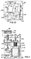
- closed sample container sampling needle and needle drive assembly 28 will readily be seen to comprise a vertically extending, generally L-shaped fixed support bracket 216 disposed below fixed drive shuttle support plates 208 and 210, and comprising spaced support plates 218 and 220 affixed thereto and extending perpendicularly thereof.
- Spaced support shafts 222 and 224 extend vertically between support plates 218 and 220; and a needle sleeve support bracket 226 is slidably mounted on those support shafts with freedom for vertical movement relative thereto.
- a sleeve drive motor is shown at 234 in FIG. 11, and is supported from support shaft 222.
- Sleeve drive motor 234 may take any suitable form, for example a valve controlled, double-acting pneumatic drive motor, and is operable to drive sleeve support bracket 226, and sleeve 228, between the retracted sleeve position as shown in solid lines in FIG. 12, and the extended sleeve position as shown in phantom in FIG. 12.
- a support shaft is indicated at 236 in FIG. 11, and extends vertically downward of and is fixedly supported from sleeve support bracket 226.
- a sampling needle support bracket is indicated at 238 and is slidably support from shaft 236 with freedom for vertical movement relative thereto. Bracket 238 is spring-biased as best seen in FIG. 11 away from bracket 226 by a coil spring 239.
- Tubular sampling needle 46 is supported as shown from bracket 238 to extend vertically upward therefrom through sampling needle bore 230 in tubular sleeve 228.
- a sampling needle drive motor again for example taking the form of a valve-controlled, double-acting pneumatic drive motor, is indicated at 242 in FIG. 11, and is supported from shaft 236.
- Drive motor 242 is operable independently of sleeve drive motor 234 to drive sampling needle support plate 238, and sampling needle 46, between the retracted sampling needle position as shown in solid lines in FIGS. 12 and 13, and the extended sampling needle position as shown in phantom in FIG. 12.
- Conduit 38 is operatively connected to the sampling passage, not shown, in tubular sampling needle 46 as indicated in FIG. 12.
- Closed sample container sampling valve 30 preferably takes the form of a conventional, two-way, multiport shear valve having a fixed upper (at least as seen in FIG. 1) valve body member 250, and a mating, lower valve body member 252 rotatable relative thereto as indicated by the arrow in FIG. 1 by a suitable drive motor, again for example a valve-controlled, double-acting pneumatic motor as indicated schematically at 254 in FIG. 1.
- a shear valve of this nature is disclosed in United States Patent 4,756,201 issued July 12, 1988 to Kenneth F. Uffenheimer, and assigned to the assignee hereof.
- Valve body member 252 is rotatable by drive motor 254 relative to valve body member 250 between the position thereof depicted in FIG. 1 wherein the valve connects conduits 38 and 42 through volumetric loop conduit 48, and conduit 44 to conduit 50; and a non-illustrated valve body member position wherein the valve connects conduit 40 to conduit 44 through the volumetric loop conduit 48; all for purposes described in detail hereinbelow.
- Equilibration chamber 34 is of the same configuration and manner of operation as disclosed for the like component in United States Patent 4,756,201.
- Sample pump 32 is a highly accurate, positive displacement pump taking, for example, the form of a standard syringe pump, and comprising a pump cylinder 256, and a pump plunger 258 extending therefrom.
- a suitable drive motor again for example a valve-controlled, double-acting pneumatic drive motor, is shown schematically at 260 in FIG. 1, and is operatively connected as indicated to syringe pump plunger 258 to operate the pump.
- Sample liquid dispensing well 36 comprises a vertically oriented, generally cylindrical body member 262 taking the general form of a container having a frustoconical bore 264 formed therein and connected as shown at the bore bottom to conduit 44.
- annular inlet groove as indicated at 266 is formed as shown in body member 262 at the upper portion of bore 264; and flow passages, not shown, are formed in the body member 262 connecting the respective rinse and isolation liquid supply conduits 62 and 64 to inlet groove 266 for the supply of those liquids to groove 266, and tne downward flow therefrom under the force of gravity over the entire surface of bore 264 to conduit 44.
- dispensing well 36 is fixedly disposed relative to carrier block 22 so that the upper lip 267 of the dispensing well is at essentially the same level as the respective upper lips of the open sample container disposed thereon as described hereinabove. Dispensing well 36 is supported at that level by any appropriate support means as indicated schematically at 255 in FIG. 1.
- a container of this general nature is disclosed in detail in the copending, continuation application for United States Patent, No. 4,865,993.
- Sample analysis system probe 37 may take any form appropriate to the successive insertions of the same into, and the withdrawals in turn of like quantities of sample liquids from, the respective open sample containers mounted as mounted in detail hereinabove in universal carrier block 32 as the block is indexed past the probe, or from the sample dispensing well 36, all as described in detail hereinbelow; and the successive supply of the thusly withdrawn sample liquids in turn in conventional manner to an operatively associated, automated sample liquid analysis system as indicated schematically at 270 in FIG. 1, and to which probe 37 is operatively connected by an appropriate flexible conduit as indicated schematically by line 271. To this effect, probe 37 is moveable under the control of a probe drive motor as indicated schematically at 272 in FIG.
- probe 37 is, of necessity, of somewhat fragile configuration and, in any event, totally inapplicable to direct sample from a closed sample container such as tube 128 by the piercing as required of the tube stopper 129.
- probe 37 is strictly limited in resident aspiration time in each of the sample liquid containers, and stricly limited in terms of the accelerations which can be impressed upon the probe, and the velocities at which the probe can be moved, whenever the probe is to any extent immersed in a sample liquid, or contains the same, in order to insure that at least precisely the same amount of sample liquid is aspirated by the probe and supplied in each instance to the sample liquid analysis system 270; all in the interests of the maximization of the accuracy of the successive sample liquid analysis results.
- An additional advantage of significance provided for by the disposition as described of all open sample liquid containers at essentially the same level relative to the upper surface 83 of the universal carrier block 22 resides in the fact that this greatly facilitates the placement of a common evaporation cover, not shown, over a "loaded" carrier block, or group thereof, to prevent sample liquid evaporation from the open containers while the same are awaiting presentation in turn to the sample liquid analysis system probe 37 for sampling; and this would be of particular advantage with regard to evaporation prevention from the small quantities of sample liquids as contained in the micro-sample cups 160.
- Sample liquid edge detector 54 may take the form of an electrical conductivity detector as disclosed in United States Patent 4,756,201 which is operable to detect the passage of the leading edge of a sample liquid through conduit 42 on the basis of the resultant change in electrical conductivity across the conduit, and to generate and output an electrical conductivity across the conduit, and to generate and output an electrical signal indicative.
- detector 54 may be of electro-optical configuration.
- Sampler particle trap 56 takes the form of a filter of pore size or mesh size appropriate to the trapping of all particultate matter above a predetermined size as may be contained in the sample liquids flowed therethrough in the direction of dispensing well 36.
- Suitable valves for example standard normally open solenoid controlled pinch valves are depicted schematically at 274, 276, 278, 280 and 282 in FIG. 1; and are respectively operatively associated as shown with conduits 58, 50, 42 (to both sides of equilibration chamber 34), and 60, to control liquid flow therethrough as described in detail hereinbelow.
- universal carrier block 22 and drive shuttle 24 are preferably injection molded from high strength plastics; closed sample container sampling needle preferably machined from particularly high-strength steel, needle drive assembly 28 in general machined from any appropriate metal with the exception of sleeve 228 which is preferably an injection molded plastic.
- Shear valve body members 250 and 252 are preferably formed and machined from appropriate, high strength ceramics.
- Dispensing well 36 is a machined plastic; while syringe pump 32 comprises a glass cylinder and plastic tipped, metal plunger.
- Equilibration chamber 34 is formed from drawn glass tubing. All system conduits are preferably of conventional, generally inert transparent laboratory plastics.
- the sleeve 228, conduit 38, the operative surfaces of the non-illustrated internal passages in sampling valve 30 which connect conduit 38 to volumetric loop conduit 48 and the latter to conduit 44, conduit 44, and dispensing well 36 are made or surface coated as the case may be from selected ones of a range of readily available, inert and highly hydrophobic ones of a range of readily available, inert and highly hydrophobic solid materials sucn as fluorinated or perflourinated hydrocarbons of low surface energy and proven chemical stability, for example, Teflon; while the isolation liquid is preferably constituted by any one of a range of fluorinated or perflourinated, highly hydrophobic liquids which are also inert and chemically stable, and which also exhibit low surface tension and appropriate viscosity;
- valves are schematically depicted at 294, 296, 298 and 300 in FIG. 14; and are respectively operably connected as indicated in the pressurized fluid supply conduits of double acting pneumatic drive motors 234, 242, 254 and 260; and to a standard, non-illustrated source of pressurized fluid, for example air, to control the respective operations of those drive motors.
- Drive motor valve control solenoids are schematically depicted at 302, 304, 306 and 308 in FIG.
- valves 294, 296, 298 and 300 are respectively operatively connected as indicated to valves 294, 296, 298 and 300 to control the operations thereof, and thus of the drive motors 234, 242, 254 and 260; thereby controlling at any point in time the respective positions of the sampling needle sleeve 228, the sampling needle 46, the lower body member 252 of sampling valve 30, and plunger 258 of syringe pump 32 in pump cylinder 256.
- An open source of a suitable rinse liquid which contains a surfactant to lubricate sampling needle 46 and thereby facilitate penetration thereby of closed sample container stopper 129 as described in detail hereinbelow, is indicated at 310 in FIG. 14; and a supply conduit 312, including check valve 314, extends thereinto as shown.
- a vacuum-operated diaphragm pump is depicted schematically at 316, and is operated as shown by a three-way, normally closed control valve 318 to which are connected a source of vacuum V as indicated on line 320, and a source of pressurized fluid P on line 322.
- Pumping conduit 324 extends as shown from pump 316 and includes a check valve 325; and conduit 312 joins with conduit 324 as indicated at 326 upstream of the valve.
- a valve control solenoid is indicated schematically at 328 in FIG. 14, and is operatively connected as indicated to valve 318 to control the operation thereof, and thus of pump 316.
- pumping conduit 324 is connected through valves 274 and 282 to rinse liquid supply conduits 58 and 62 for supply of rinse liquid therethrough to passage 230 in sampling needle sleeve 228, and bore 264 of dispensing well 36, respectively.
- Conduit 332 connects as indicated with each of conduits 60 and 64; and respective pump rollers of a conventional peristaltic pump as indicated schematically at 334 and 336 are operatively associated as shown with conduits 60 and 64 to pump liquids therethrough.
- a peristaltic pump electric drive motor as shown schematically at 338, and operates as indicated to drive pump rollers 334 and 336 to thereby provide precisely predetermined and extremely small quantities of the isolation liquid from source 330 to sleeve passage 230 and dispensing well bore 264 upon drive motor actuation.
- a system controller taking, for example, the form of an appropriately programmed micro-processor or like device, is depicted schematically at 350; and is operatively electrically connected as indicated to all electrically powered components of the integrated sampler 20 of my invention, and to the sample liquid analysis system 270 to which sample liquids are to be supplied in turn by that sampler, to control and synchronize as required the respective operations thereof.
- system controller 350 is electrically connected as indicated by lines 352 and 354 to detectors 26 and 54, respectively, and is electrically connected as indicated by lines 356, 358, 360 and 362 to solenoids 302, 304, 306 and 308 to input control signals thereto to control and synchronize the respective operations of the sleeve drive motor 234, the needle drive motor 242, the sampling valve drive motor 254, and the sample pump drive motor 260; thereby controlling and synchronizing the respective operations of the sleeve 228, the sampling needle 46, the sampling valve 30 and the sample pump 32.
- Lines 364 and 366 electrically connect system controller 350 to shuttle drive motor 213 and probe drive motor 272 to control and synchronize the respective operations of the drive shuttle and 24 and the sampling probe 37; wnile lines 368 and 370 electrically connect the controller 350 to isolation liquid pump drive motor 338, and the control solenoid 328 for rinse liquid pump drive motor control valve 318 to thereby control and synchronize the respective operations of the isolation liquid peristaltic pump rollers 334 and 336, and the rinse liquid pump 316.
- Controller 350 is also electrically connected as indicated by lines 370, 372, 374, 376 and 378 to control and synchronize the respective operations of the pinch valve control solenoids 284, 286, 288, 290 and 292; thereby controlling and synchronizing the supply of rinse liquid to the sleeve passage 230, the drain of sample and rinse liquids by vacuum to waste through conduit 50, the connection of the equilibration chamber 34 to the sampling needle 46 for pressure equilibration of tne closed sample container 128 as described in detail hereinbelow, the connection of the equilibration chamber 34 to vacuum and waste for the drain of excess sample liquid therethrough, and the supply of the rinse liquid to dispensing well 36, respectively.
- System controller 350 is also electrically connected as indicated by line 380 to the sample liquid analysis system 270 to synchronize and control the operation of the integrated sampler 20 of my invention in accordance with the operation of that sample liquid analysis system, and vice versa .
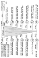
- FIG. 16 illustrates the operational conditions of the indicated components of the integrated sampler 20 of my invention as drawn to the same time scale. More specifically, in FIG. 16 waveforms 384, 386, 388, 390 and 392 respectively illustrate the operational conditions of sampler valves 294, 296, 274, 298 and 300; while waveforms 394, 396, 398, 400 and 402 respectively illustrate the operational conditions of sampler valves 278, 280, 276, 282 and 318. Waveform 404 illustrates the operational condition of isolation liquid pump drive motor 338.
- the identification data for the sample liquid contained in micro-sample cup 160 as appears on the non-illustrated sample liquid identification card operatively disposed as heretofore described in mounting slots 114 and 116 for carrier block mounting aperture 74 is "read" by sample liquid identification detector 26 and outputted to system controller 350 on line 352 for supply in turn by the controller to the sample liquid analysis system 270 on line 380 to insure exact correlation between that sample liquid and the analysis results therefor.
- micro-sample cup 160 is an open sample container and, as such, does not include an enlarged cap 140 with reflective strip 141, no signal indicative of a closed sample container in universal carrier block mounting aperture 74 will be outputted by detector 26 to system controller 350; whereby closed sample container sampling needle and needle drive assembly 28, sampling valve 30, and sample pump 32 will not be activated attendant sampling as described from micro-sample cup 160.
- carrier block 22 is again indexed as described to place open sample tube 132 in "sampling" position relative to probe 37, whereupon sampling of the sample liquid from liquid level adjusting device 134 in that tube by appropriate movement of probe 37 as described is accomplished; again with concomitant detection and outputting by detector 26 of the sample liquid identification data from label 156 on tube 132.
- tube 132 is an open sample container and does not include cap 140, no signal is outputted from detector 26 to controller 350 for activation of the closed tube sampling needle drive assembly 28 and related integrated sampler components as specified hereinabove with regard to sampling from open micro-sample cup 160.
- both micro-sample cup 160 and liquid level adjusting device 134 function as described to retain the respective sample liquids contained therein at the same level relative to the upper surface of the universal carrier block 22, and thus at the same level relative to the inlet end 382 of the probe 37, the travel of which is precisely fixed as described, it will be clear that immersion of the probe to the same extent in the respective sample liquid sample contained in cup 160 and tube 132 is insured; thereby in turn insuring consistent and complete sample liquid aspiration by probe 37 from each of cup 160 and tuoe 132 for supply to sample liquid analysis system 270 with attendant maximization of the accuracy of the sample liquid analysis results as set forth hereinabove.
- universal carrier block 22 is again indexed as described through appropriate actuation of shuttle drive motor 213 by system controller 350 on line 364 to place closed sample tube 152 in sampling position which, in this instance, is most relevantly defined in accordance witn FIG. 12 wherein aligned sampling apertures 96 of the carrier block 22 and 196 of the drive shuttle 24 are disposed directly above sampling needle 46 and sleeve 228 and in direct alignment therewith.
- system controller 350 activates probe drive motor 272 on line 366 to move probe 37 from the retracted position thereof of FIG. 1 directly over the carrier block 22 to the retracted position thereof of FIG. 1 directly over the sample liquid dispensing well 36.
- controller 350 activates solenoid 302 on line 356 to shift valve 294 and operate sleeve drive motor 234 to rapidly move sleeve 228 vertically upward into and through drive shuttle aperture 196 from the retracted to extended sleeve positions of the sleeve as respectively depicted in solid and phantom lines in FIG. 12.
- controller 350 activates solenoid 304 on line 358 to shift valve 296 as indicated by waveform 386 in FIG. 15 to operate sampling needle drive motor 242 to rapidly move the sampling needle 46 vertically upward into and through the aligned drive shuttle and carrier block sampling apertures 196 and 96 from the retracted to extended sampling needle positions as respectively depicted in solid and phantom lines in FIG.
- sample aspiration valve 278 is open as sampling needle 46 pierces closed tube stopper 129, equilibration of the pressure within closed sample tube 128 with the atmospheric pressure then prevailing in equilibration chamber 34, through the open needle end 408, conduit 38, sampling valve 30, volumetric conduit loop 48, sampling valve 30, and conduit 42 will then immediately occur, all in the manner and to the significant advantages with regard to insuring a full and consistent sample "pull" by needle 46 from closed sample tube 128 as disclosed in detail in United States Patent 4,756,201.
- Waveform 396 of FIG. 15 makes clear that pressure equilibration in closed sample tube is virtually immediately followed by the activation on line 376 by controller 350 of solenoid 290 to open sample aspiration control valve 280, thereby connecting equilibration chamber 34 and the open sampling needle end 408 to vacuum through conduit 52; whereupon aspiration of the sample liquid 410 from closed tube 128 is commenced through needle 46, conduit 38, sampling valve 30, volumetric loop conduit 48, sampling valve 30, conduit 42, the equilibration chamber 34, and conduit 52 which connects the same to vacuum as indicated on FIG. 1.
- edge detector 54 outputs a signal indicative thereof to system controller 350; whereupon the controller activates solenoid on line 344 to close sample aspiration valve 278, as made clear by waveform 394 of FIG. 16, thereby discontinuing the aspiration of sample liquid 410 for closed sample tube 128.
- Discontinuation as described of sample liquid aspiration from closed sample tube 128 is virtually immediately followed as illustrated by waveforms 384 and 386 of FIG. 15, by operation of system controller 350 to activate solenoids 302 and 304 on lines 356 and 358 to shift valves 294 and 296 to operate the sleeve and sampling needle drive motors to return the sleeve 28 and sampling needle 46 to the respective retracted positions thereof of FIG. 12; and by the activation by controller 350 of solenoid 328 on line 370 to shift valve 318 to operate rinse liquid pump 316 to commence the pumping of rinse liquid as illustrated by waveform 402 in FIG. 16. Concomitantly, system controller 350 activates solenoid 306 on line 360 to shift valve 298 as shown by waveform 390 in FIG.
- sampling valve drive motor 254 to rotate valve body member 252 relative to valve body member 250 to the non-illustrated relative positions thereof wherein the volumetric loop conduit 48 connects conduit 40 to conduit 44; thereby connecting sample pump 32 to dispensing well 36 through the sampling valve 30.
- system controller 350 activates solenoid 308 on line 362 to shift valve 300 as shown by waveform 390 in FIG.
- system controller again activates solenoid 306 on line 360 to shift valve 306 as shown by waveform 390 in FIG. 16 to operate drive motor 254 to return the sampling valve 30 to the FIG. 1 position thereof; and, through solenoid 308, valve 300 and drive motor 260 deactivates and resets sample pump 32 as shown by waveform 392 in FIG. 16.
- controller 350 activates probe drive motor 272 on line 366 to move probe 37 from the retracted to extended positions thereof into the sample liquid 410 now supplied as described to the dispensing well 36 for sampling thereof and supply of a precisely predetemined sample liquid quantity to sample liquid analysis system 270 via conduit 271, and immediate return of the probe 37 to the retracted probe position.
- controller 350 activates solenoid 284 on line 370 to open valve 274 as shown by waveform 388 to commence the flow of the rinse and surfactant liquids to the tubular passage 230 in sleeve 28 through conduit 58, and thus to the open tip 408 of the sampling needle 46; thereby thoroughly rinsing the exterior of the sampling needle of the residue of sample liquid 410, and lubricating with the surfactant liquid the sampling needle tip 48 and relevant exterior surface thereof to greatly facilitate the penetration thereby of the stopper of a succeeding closed sample container to minimize stopper particle generation and attendant contamination thereby of the sample liquid from that succeeding closed sample liquid container.
- System controller 350 tnen also activates peristaltic pump drive motor 338 on line 368 as shown by waveform 404 in FIG. 16 to operate pump rollers 334 and 336 to commence the flow of the isolation liquid from source 330 in conduits 332, 60 and 64 to the tubular sleeve passage 230 and the bore 264 of the dispensing well 36, respectively.
- system controller 350 then activates solenoid 288 on line 374 to reopen aspiration valve 278 as shown by waveform 394 in FIG.
- isolation liquid is flowed with the rinse and surfactant liquids from sleeve passage 230 through the entire sample liquid aspiration path as described; and this small isolation liquid quantity functions to replenish the thin isolation liquid layer which coats the same in accordance with the aspiration as described of sample liquids from preceding closed sample containers.
- sample liquid carryover from the closed sample container sample liquid aspiration path upon the aspiration as described of a sample liquid from a succeeding closed sample container is virtually eliminated, or certainly reduced to levels well below those of highly stringent, contemporary clinical significance, for example, one part of a preceding sample liquid in 100,000 parts of a succeeding sample liquid.
- Sample liquid edge detector 54 is electrically disabled by system controller 350 during sample liquid aspiration path rinse as described to prevent the actuation of sampling valve 30 by that detector upon rinse liquid passage through the latter.
- solenoid 290 is activated by system controller 350 on line 376 to close valve 280 as shown by waveform 396 in FIG. 16, and solenoid 286 is activated by system controller 350 on line 372 to open sample liquid drain valve 276 as shown by waveform 398 in FIG. 16, thereby draining the remaining sample liquid 410 from the dispensing well 36 to vacuum and waste through conduit 44, sampling valve 30, and drain conduit 50.
- controller 350 activates solenoids 286 and 292 on lines 372 and 378 to reclose valve 276 and open dispensing well rinse liquid control valve 282, as respectively shown by waveforms 398 and 400 in FIG.
- Controller 350 then activates solenoid 286 on line 372 to re-open drain valve 276 as shown by waveform 398 to flow the accumulated rinse liquid, followed by ambient air for drying, from well bore 264 through conduit 44, sample liquid particle trap 56, and sampling valve 30 --thereby forcibly backflushing the same against the initial direction of flow of the sample liquid 410 therethrough-- and drain conduit 50 to vacuum and waste.
- hydrophobic isolation liquid-coated surfaces of dispensing well bore 264, conduit 44, and the relevant internal passages of sampling valve 30, are forcibly backflushed and cleansed of virtually all residue of sample liquid 410, to again virtually eliminate the contamination thereby of the sample liquid from a succeeding closed sample liquid container on universal carrier block 22.
- the extremely small quantity of the isolation liquid from source 330 (FIG. 14) supplied as previously described in detail with reference to waveform 404 of FIG. 16 to the bore 264 of the dispensing well 36 flows with this rinse liquid, although at a much lower flow rate, to replenish the extremely thin isolation liquid layer on the hydrophobic surfaces of dispensing well bore 264, conduit 44, and the relevant passages in sampling valve 30.
- the new and improved integrated sampler 20 of my invention insures sample liquid carryover minimization from the point of sample liquid supply to the probe for aspiration, be it from a closed or open sample liquid container, virtually to the point of sample liquid analysis by the analysis system 270; thereby contributing very significantly to the overall accuracy of the sample liquid analysis results.
Landscapes
- Physics & Mathematics (AREA)
- Health & Medical Sciences (AREA)
- Life Sciences & Earth Sciences (AREA)
- Chemical & Material Sciences (AREA)
- Analytical Chemistry (AREA)
- Biochemistry (AREA)
- General Health & Medical Sciences (AREA)
- General Physics & Mathematics (AREA)
- Immunology (AREA)
- Pathology (AREA)
- Sampling And Sample Adjustment (AREA)
- Automatic Analysis And Handling Materials Therefor (AREA)
- Supplying Of Containers To The Packaging Station (AREA)
Abstract
Claims (31)
- Échantillonneur intégré (20) à utiliser conjointement avec un moyen formant sonde d'échantillon liquide (37) pour fournir des échantillons liquides tour à tour à un moyen d'analyse d'échantillon liquide (270), ledit échantillonneur comprenant un moyen de support (22, 70) prévu pour supporter à la fois des récipients d'échantillon liquide (128) fermés et des récipients d'échantillon liquide (120, 132, 160) ouverts sur le même moyen de support de récipient d'échantillon liquide, et des moyens (24, 36, 46) associés en fonctionnement audit moyen de support de récipient d'échantillon liquide (22, 70) pour échantillonner des liquides à partir de récipients d'échantillon liquide fermés et ouverts, disposés de manière aléatoire sur ledit support, en fournissant lesdits échantillons liquides tour à tour au moyen formant sonde d'échantillon de liquide.
- Échantillonneur intégré selon la revendication 1, dans lequel ledit moyen pour échantillonner des liquides contenus dans lesdits récipients fermés d'échantillon liquide comprennent un moyen de distribution d'échantillon liquide (36), associé en fonctionnement audit moyen de support de récipient d'échantillon liquide (22, 70) et accessible audit moyen formant sonde (37), et un moyen (46) servant à transférer des échantillons liquides depuis lesdits récipients d'échantillon liquide (128) fermés, supportés par ledit moyen de support (22, 70), audit moyen de distribution (36) pour permettre l'accès audit moyen formant sonde (37).
- Échantillonneur intégré selon la revendication 2, comprenant en outre des moyens (58, 60, 62, 310) prévus pour rincer ledit moyen de transfert d'échantillon liquide (46) et ledit moyen de distribution d'échantillon liquide (36), à l'aide d'un liquide de rinçage après le transfert et la distribution d'échantillon liquide, de manière à en éliminer le résidu d'échantillon liquide, afin de minimiser toute contamination d'un échantillon liquide successif par ce résidu d'échantillon liquide.
- Échantillonneur intégré selon la revendication 3, comprenant en outre un moyen pour segmenter à l'air ledit liquide de rinçage, de manière que son action de rinçage sur le résidu d'échantillon liquide soit améliorée et que la consommation dudit liquide de rinçage soit réduite.
- Échantillonneur intégré selon la revendication 3 ou 4, dans lequel lesdits récipients d'échantillon (128) fermés comprennent des récipients d'échantillon liquide qui sont fermés à une extrémité par des obturateurs perçables (129), ledit moyen servant à transférer des échantillons liquides depuis les récipients fermés comprend une aiguille d'échantillonnage (46) servant à percer lesdits obturateurs de récipients d'échantillon liquide (129) pour extraire les échantillons liquides depuis lesdits récipients (128), et dans lequel ledit moyen de rinçage (58, 60, 62, 310) comprend des moyens (330, 332) prévus pour permettre l'écoulement d'un liquide tensio-actif sur ladite aiguille d'échantillonnage (46), avec ledit liquide de rinçage, pour lubrifier cette dernière et faciliter ainsi la pénétration par ladite aiguille d'échantillonnage de l'obturateur d'un récipient fermé successif d'échantillon liquide, de manière à minimiser toute contamination d'un échantillon liquide provenant d'un récipient successif fermé d'échantillon liquide par des particules de l'obturateur de récipient.
- Échantillonneur intégré selon l'une quelconque des revendications 2, 3, 4 ou 5, dans lequel ledit moyen servant à transférer des échantillons liquides depuis lesdits récipients fermés (46) comprennent des moyens pour transférer des volumes prédéterminés, seulement, desdits échantillons liquides.
- Échantillonneur intégré selon la revendication 3 ou 4, dans lequel lesdits échantillons liquides sont des liquides aqueux, lesdits moyens de transfert et de distribution d'échantillon liquide (36, 46) ont des surfaces intérieures hydrophobes d'écoulement d'échantillon liquide et un moyen (330, 332) est prévu pour permettre l'écoulement d'un liquide d'isolation, qui humidifie sélectivement les surfaces hydrophobes pour exclure pratiquement toute trace d'échantillon liquide aqueux sur ces surfaces, de manière à les recouvrir d'une couche dudit liquide d'isolation qui empêche l'adhérence à ces dernières de résidus aqueux d'échantillon liquide, de manière à minimiser toute contamination d'échantillon liquide aqueux successif par les résidus d'échantillons liquides aqueux précédents.
- Échantillonneur intégré selon l'une quelconque des revendications 2 à 7, dans lequel lesdits moyens (24, 36) prévus pour échantillonner des liquides depuis lesdits récipients d'échantillon liquide (120, 132, 160) ouverts vers ledit moyen formant sonde (37) servent à présenter directement lesdits récipients d'échantillon ouverts audit moyen formant sonde (37) pour les échantillonner.
- Échantillonneur intégré selon l'une quelconque des revendications 2 à 8, dans lequel ledit moyen de support de récipient d'échantillon liquide (22, 70) sert à supporter lesdits récipients d'échantillon liquide (120, 132, 160) ouverts essentiellement au même niveau par rapport audit moyen formant sonde (37).
- Échantillonneur intégré selon la revendication 9, comprenant en outre un moyen (265) pour supporter ledit moyen de distribution d'échantillon liquide (36) essentiellement au même niveau.
- Échantillonneur intégré selon l'une quelconque des revendications 1 à 10, comprenant en outre un moyen de maintien de récipient d'échantillon liquide (130) fermé associé en fonctionnement audit moyen de support (22, 70) et servant à maintenir les récipients d'échantillon liquide (128) fermés ainsi supportés.
- Échantillonneur intégré selon l'une quelconque des revendications 1 à 11, dans lequel ledit moyen de support (22, 70) comprend en outre un moyen (114, 116) pour supporter un moyen d'identification d'échantillon liquide (122) afin d'identifier les échantillons liquides dans lesdits récipients d'échantillon liquide, et il est prévu en outre un moyen de détection (26), associé en fonctionnement audit moyen de support (22, 70), pour détecter ledit moyen d'identification d'échantillon liquide (122) afin d'identifier lesdits échantillons liquides.
- Échantillonneur intégré selon l'une quelconque des revendications 1 à 11, comprenant en outre un moyen de détection (26) associé en fonctionnement audit moyen de support (22, 70) et servant à effectuer une différenciation entre les récipients d'échantillon liquide fermés et ouverts, supportés par ledit moyen de support (22,70).
- Échantillonneur intégré selon l'une quelconque des revendications 1 à 13, dans lequel ledit moyen de support comprend une pluralité de moyens de montage de récipient d'échantillon liquide (72, 74, 76, 78, 80, 82), servant chacun à monter un récipient d'échantillon liquide (128) fermé ou bien un récipient d'échantillon liquide (120, 132, 160) ouvert et un moyen de connexion pour connecter en fonctionnement le moyen de support audit échantillonneur.
- Échantillonneur intégré selon la revendication 14, dans lequel lesdits moyens de montage sont espacés les uns par rapport aux autres.
- Échantillonneur intégré selon la revendication 14 ou 15, dans lequel chacun desdits moyens de montage de récipient d'échantillon liquide comprend une ouverture de montage de récipient d'échantillon liquide (72, 74, 76, 80, 82) pour assurer le montage en son sein d'un récipient d'échantillon liquide.
- Échantillonneur intégré selon la revendication 16, dans lequel lesdites ouvertures de montage (72, 74, 76, 80, 82) sont orientées globalement verticalement, chacune desdites ouvertures servant à monter en son sein un récipient d'échantillon liquide (128) fermé avec l'extrémité du récipient fermé orientée vers le bas, ou un récipient d'échantillon liquide (120, 132, 160) ouvert avec l'extrémité du récipient ouvert tournée vers le haut.
- Échantillonneur intégré selon la revendication 16 ou 17, comprenant en outre un moyen de maintien d'échantillon liquide (130) fermé associé en fonctionnement auxdites ouvertures de montage de récipient d'échantillon liquide et servant à maintenir en son sein des récipients d'échantillon liquide (128) fermés.
- Échantillonneur intégré selon l'une quelconque des revendications 14 à 18, dans lequel lesdits moyens de montage de récipient d'échantillon liquide servent à monter lesdits récipients d'échantillon liquide (120, 132, 160) ouverts essentiellement au même niveau par rapport audit moyen de support.
- Procédé d'échantillonnage intégré à utiliser conjointement avec un moyen formant sonde d'échantillon liquide (37) pour fournir des échantillons liquides tour à tour à un moyen d'analyse d'échantillon liquide (270); ledit procédé comprenant les étapes consistant à: supporter des récipients d'échantillon liquide (128) fermés et des récipients d'échantillon liquide (120, 132, 160) ouverts disposés de façon aléatoire sur le même moyen de support de récipient d'échantillon liquide (22, 70) et à utiliser un moyen fonctionnel (24,36,46) associé audit moyen de support de récipient d'échantillon liquide (22,70) pour présenter les échantillons liquides, provenant desdits récipients d'échantillon liquide fermés et ouverts, au même moyen formant sonde d'échantillon liquide (37) tour à tour pour assurer une amenée en avant, par ledit moyen formant sonde, audit moyen d'analyse d'échantillon liquide (270).
- Procédé selon la revendication 20, dans lequel les étapes de présentation d'échantillon liquide contenu dans lesdits récipients d'échantillon liquide fermés audit moyen formant sonde comprennent en outre l'utilisation d'un moyen servant à transférer un échantillon liquide depuis lesdits récipients d'échantillon (46) fermés, afin de transférer lesdits échantillons liquides depuis lesdits récipients d'échantillon liquide (128) fermés à des moyens de distribution d'échantillon liquide (36) qui sont accessibles par ledit moyen formant sonde (37) pour fournir lesdits échantillons liquides, tour à tour, par ledit moyen formant sonde (37), audit moyen d'analyse (270).
- Procédé selon la revendication 21, comprenant en outre les étapes de rinçage dudit moyen servant à transférer les échantillons liquides depuis lesdits récipients d'échantillon (46) fermés et dudit moyen de distribution d'échantillon liquide (36) à l'aide d'un liquide de rinçage, après le transfert et la distribution d'échantillon liquide, de manière à en éliminer tout résidu d'échantillon liquide, afin de minimiser toute contamination d'un échantillon liquide successif par ce résidu d'échantillon liquide.
- Procédé selon la revendication 22, comprenant en outre les étapes de segmentation pneumatique dudit liquide de rinçage, de manière que son action de rinçage sur le résidu d'échantillon liquide soit améliorée et que la consommation de liquide de rinçage soit réduite.
- Procédé selon la revendication 21, 22 ou 23, comprenant en outre le transfert de volumes prédéterminés seulement desdits échantillons liquides, depuis lesdits récipients d'échantillon liquide (128) fermés vers ledit moyen de distribution d'échantillon liquide (36).
- Procédé selon l'une quelconque des revendications 21 à 24, dans lequel les étapes de présentation d'échantillons liquides contenus dans lesdits récipients d'échantillon (120, 132, 160) ouverts audit moyen formant sonde (37) comprennent la présentation directement desdits récipients d'échantillon liquide ouverts audit moyen formant sonde (37), en vue de les échantillonner.
- Procédé selon l'une quelconque des revendications 22 à 25, dans lequel lesdits échantillons liquides sont des liquides aqueux et lesdits moyens de transfert et de distribution d'échantillon liquide (46, 36) ont des surfaces intérieures hydrophobes d'écoulement d'échantillon liquide, et le procédé comprend en outre les étapes d'écoulement d'un liquide d'isolation qui humidifie sélectivement les surfaces hydrophobes pour assurer partiquement l'exclusion d'échantillons liquides aqueux, sur ces surfaces intérieures hydrophobes des moyens de transfert et de distribution d'échantillon liquide, de manière à les recouvrir d'une couche dudit liquide d'isolation qui empêche l'adhérence à ces dernières d'un résidu d'échantillon aqueux, de manière à minimiser toute contamination d'échantillon liquide aqueux successif par le résidu d'échantillon liquide aqueux précédent.
- Procédé selon l'une quelconque des revendications 22 à 26, dans lequel lesdits récipients d'échantillon liquide (128) fermés comprennent des récipients d'échantillon liquide qui sont fermés à une extrémité par des obturateurs perçables (129), et ledit moyen servant à transférer des échantillons liquides depuis lesdits récipients d'échantillon fermés comprend une aiguille d'échantillonnage (46) qui sert à percer les obturateurs de récipients d'échantillon (129) pour extraire des échantillons liquides desdits récipients et le procédé comprend en outre les étapes d'écoulement d'un liquide tensio-actif, conjointement avec ledit liquide de rinçage, sur ladite aiguille d'échantillonnage (46), pour la lubrifier et faciliter ainsi la pénétration de ladite aiguille d'échantillonnage dans l'obturateur d'un récipient fermé successif d'échantillon liquide, de manière à minimiser toute contamination de l'échantillon liquide provenant du récipient fermé successif d'échantillon liquide par des particules de l'obturateur de récipient.
- Procédé selon l'une quelconque des revendications 20 à 27, comprenant en outre le maintien desdits récipients fermés d'échantillon liquide supportés sur le moyen de support de récipient d'échantillon liquide.
- Procédé selon l'une quelconque des revendications 21 à 28, dans lequel les étapes consistant à supporter lesdits récipients d'échantillon (120, 132, 160) ouverts sur ledit moyen de support de récipient d'échantillon liquide (22, 70) comprennent le maintien desdits récipients d'échantillon ouverts sensiblement au même niveau que ledit moyen formant sonde (37) et le maintien dudit moyen de distribution d'échantillon liquide (36), sensiblement au même niveau que ledit moyen formant sonde (37).
- Procédé selon l'une quelconque des revendications 20 à 29, comprenant en outre le maintien d'un moyen d'identification d'échantillon liquide (122) pour identifier l'échantillon liquide contenu dans lesdits récipients d'échantillon liquide sur ledit moyen de support et la détection dudit moyen d'identification d'échantillon liquide pour identifier lesdits échantillons liquides.
- Procédé selon l'une quelconque des revendications 20 à 30, comprenant en outre la détection desdits récipients ouverts et fermés d'échantillon liquide sur ledit moyen de support, pour effectuer une différenciation entre eux.
Priority Applications (1)
| Application Number | Priority Date | Filing Date | Title |
|---|---|---|---|
| AT89903018T ATE134269T1 (de) | 1988-12-29 | 1988-12-29 | Integrierter probennehmer für geschlossene und offene probencontainer |
Applications Claiming Priority (1)
| Application Number | Priority Date | Filing Date | Title |
|---|---|---|---|
| PCT/US1988/004630 WO1990008307A1 (fr) | 1988-12-29 | 1988-12-29 | Echantillonneur integre pour eprouvettes fermees et ouvertes |
Publications (3)
| Publication Number | Publication Date |
|---|---|
| EP0452308A1 EP0452308A1 (fr) | 1991-10-23 |
| EP0452308A4 EP0452308A4 (en) | 1992-09-16 |
| EP0452308B1 true EP0452308B1 (fr) | 1996-02-14 |
Family
ID=22209066
Family Applications (1)
| Application Number | Title | Priority Date | Filing Date |
|---|---|---|---|
| EP89903018A Expired - Lifetime EP0452308B1 (fr) | 1988-12-29 | 1988-12-29 | Echantillonneur integre pour eprouvettes fermees et ouvertes |
Country Status (10)
| Country | Link |
|---|---|
| US (1) | US5201232A (fr) |
| EP (1) | EP0452308B1 (fr) |
| JP (1) | JP2511549B2 (fr) |
| AU (1) | AU635547B2 (fr) |
| CA (1) | CA1337100C (fr) |
| DE (1) | DE3855010T2 (fr) |
| DK (1) | DK124791A (fr) |
| ES (1) | ES2016696A6 (fr) |
| IL (2) | IL89905A (fr) |
| WO (1) | WO1990008307A1 (fr) |
Cited By (6)
| Publication number | Priority date | Publication date | Assignee | Title |
|---|---|---|---|---|
| USD531736S1 (en) | 2005-05-04 | 2006-11-07 | Abbott Laboratories | Reagent carrier for use in an automated analyzer |
| USD532524S1 (en) | 2005-05-04 | 2006-11-21 | Abbott Laboratories | Reagent carrier for use in an automated analyzer |
| USD533947S1 (en) | 2005-05-04 | 2006-12-19 | Abbott Laboratories | Reagent carrier for use in an automated analyzer |
| USD534280S1 (en) | 2005-05-04 | 2006-12-26 | Abbott Laboratories | Reagent carrier for use in an automated analyzer |
| US7628954B2 (en) | 2005-05-04 | 2009-12-08 | Abbott Laboratories, Inc. | Reagent and sample handling device for automatic testing system |
| US8449839B2 (en) | 2006-12-22 | 2013-05-28 | Abbott Laboratories | Liquid waste management system |
Families Citing this family (27)
| Publication number | Priority date | Publication date | Assignee | Title |
|---|---|---|---|---|
| US4984475A (en) * | 1989-07-24 | 1991-01-15 | Tritech Partners | Ultra low carryover sample liquid analysis apparatus and method |
| DE4023149A1 (de) * | 1990-07-20 | 1992-01-23 | Kodak Ag | Vorrichtung zum abtasten von behaeltern mit einer fluessigkeit |
| US5080864A (en) * | 1990-07-20 | 1992-01-14 | Eastman Kodak Company | Stopper detector |
| US5137693A (en) * | 1990-07-30 | 1992-08-11 | Miles Inc. | Spring biased test tube holder |
| DE4223116A1 (de) * | 1992-04-30 | 1993-11-04 | Mikrowellen Labor Systeme | Vorrichtung zur verdampfungsbehandlung von vorzugsweise fluessigen stoffen, insbesondere reagenzstoffen, oder zum aufbereiten oder analysieren von probenmaterial |
| US5483843A (en) * | 1992-06-01 | 1996-01-16 | Thermo Separation Products Inc. | Transport apparatus |
| US5558838A (en) * | 1993-09-29 | 1996-09-24 | Becton Dickinson And Company | Sample preparation apparatus |
| US5517867A (en) * | 1994-07-15 | 1996-05-21 | E. I. Du Pont De Nemours And Company | Liquid extraction apparatus |
| EP0692717B1 (fr) | 1994-07-15 | 2000-03-15 | Dade Chemistry Systems Inc. | Appareil d'analyse |
| EP0847531A1 (fr) * | 1995-08-30 | 1998-06-17 | Radiometer Medical A/S | Introduction automatique de fluides de reference dans un appareil d'analyse de fluides physiologiques |
| DE19540877C2 (de) * | 1995-11-02 | 1998-02-26 | Byk Sangtec Diagnostica | Modulare Reagenzienkartusche |
| IT1283806B1 (it) * | 1996-08-14 | 1998-04-30 | Guido F Vicario | Dispositivo automatico per il prelievo frazionato dalla vena di sangue in condizioni isobariche per l'erogazione contestuale di |
| JP3032159B2 (ja) * | 1996-09-24 | 2000-04-10 | 株式会社日立製作所 | 分析システム |
| US5861563A (en) * | 1997-03-20 | 1999-01-19 | Bayer Corporation | Automatic closed tube sampler |
| US5935523A (en) * | 1997-05-29 | 1999-08-10 | Medical Laboratory Automation, Inc. | Apparatus for accessing a sealed container |
| US6331437B1 (en) * | 1998-07-14 | 2001-12-18 | Bayer Corporation | Automatic handler for feeding containers into and out of an analytical instrument |
| EP0984285B1 (fr) * | 1998-08-31 | 2004-01-07 | Sysmex Corporation | Aspirateur d'échantillons avec coopération de deux moteurs |
| DE19902601A1 (de) * | 1999-01-23 | 2000-07-27 | Roche Diagnostics Gmbh | Verfahren und Vorrichtung zum Entnehmen analytischer Verbrauchsmittel aus einem Vorratsbehältnis |
| US6809804B1 (en) | 2000-05-11 | 2004-10-26 | Becton, Dickinson And Company | System and method for providing improved event reading and data processing capabilities in a flow cytometer |
| US6627156B1 (en) * | 2000-06-22 | 2003-09-30 | Beckman Coulter, Inc. | Cap piercing station for closed container sampling system |
| US7988933B2 (en) * | 2006-09-01 | 2011-08-02 | Siemens Healthcare Diagnostics Inc. | Identification system for a clinical sample container |
| JP5431755B2 (ja) * | 2008-10-31 | 2014-03-05 | シスメックス株式会社 | 検体分析装置および検体分析方法 |
| US9039992B2 (en) | 2011-06-06 | 2015-05-26 | Abbott Laboratories | Apparatus for closed tube sampling and open tube sampling for automated clinical analyzers |
| WO2017223214A1 (fr) | 2016-06-22 | 2017-12-28 | Abbott Laboratories | Appareil de détection de niveau de liquide et procédés associés |
| CN108332995A (zh) * | 2017-01-20 | 2018-07-27 | 上海溯源生物技术有限公司 | 取样机 |
| EP4142946A4 (fr) * | 2020-05-01 | 2024-04-24 | Agilent Technologies, Inc. | Dispositifs et procédés de lavage de pointe de pipette |
| US12203953B2 (en) | 2020-07-29 | 2025-01-21 | Siemens Healthcare Diagnostics Inc. | Helix wash station that augments the fluid dynamics associated with clinical chemistry and immunoassay probe cleaning |
Citations (1)
| Publication number | Priority date | Publication date | Assignee | Title |
|---|---|---|---|---|
| US3981200A (en) * | 1974-09-02 | 1976-09-21 | U.S. Philips Corporation | Method of automatically transferring and injecting a liquid sample |
Family Cites Families (17)
| Publication number | Priority date | Publication date | Assignee | Title |
|---|---|---|---|---|
| SE327840B (fr) * | 1968-01-25 | 1970-08-31 | Atuokemi Ab | |
| US3630088A (en) * | 1969-02-27 | 1971-12-28 | Nat Res Dev | Sample supply apparatus |
| US3712794A (en) * | 1971-01-26 | 1973-01-23 | Farr Devices Inc | Laboratory pipette and diluter device |
| US3897216A (en) * | 1971-11-03 | 1975-07-29 | Coulter Chemistry Inc | Sample cup holder |
| US3791556A (en) * | 1971-12-13 | 1974-02-12 | N Tarter | Fluid metering device |
| DE2218569B2 (de) * | 1972-04-17 | 1979-04-19 | Siemens Ag, 1000 Berlin Und 8000 Muenchen | Probenverteiler fuer fluessiges untersuchungsgut und verfahren zu seinem betrieb |
| US3912456A (en) * | 1974-03-04 | 1975-10-14 | Anatronics Corp | Apparatus and method for automatic chemical analysis |
| US3960020A (en) * | 1974-12-30 | 1976-06-01 | Technicon Instruments Corporation | Liquid aspirating probe assembly of a supply analyzer |
| US4124122A (en) * | 1976-04-21 | 1978-11-07 | Emmitt Ronald W | Test tube rack |
| US4478095A (en) * | 1981-03-09 | 1984-10-23 | Spectra-Physics, Inc. | Autosampler mechanism |
| DE3229118A1 (de) * | 1981-08-05 | 1983-03-24 | Varian Techtron Proprietary Ltd., 3170 Mulgrave, Victoria | Vorrichtung zum handhaben von proben |
| DE3405292A1 (de) * | 1984-02-15 | 1985-09-05 | Eppendorf Gerätebau Netheler + Hinz GmbH, 2000 Hamburg | Verfahren zum durchfuehren von probenanalysen sowie rack zur durchfuehrung des verfahrens |
| DE8413879U1 (de) * | 1984-05-08 | 1985-09-05 | Ballies, Uwe Werner, Dr.Med., 2300 Kiel | Röhrchenständer mit Evakuiereinrichtung |
| US4751052A (en) * | 1985-07-22 | 1988-06-14 | Sequoia-Turner Corporation | Tube alignment apparatus |
| US4756201A (en) * | 1985-09-03 | 1988-07-12 | Technicon Instruments Corporation | Apparatus and method for combined closed and open tube sampling |
| US4713974A (en) * | 1986-04-18 | 1987-12-22 | Varian Associates, Inc./Scientific Systems, Inc. | Autosampler |
| US4861553A (en) * | 1987-06-11 | 1989-08-29 | Technicon Instruments Corporation | Automatic sampling system |
-
1988
- 1988-12-29 JP JP1503045A patent/JP2511549B2/ja not_active Expired - Lifetime
- 1988-12-29 WO PCT/US1988/004630 patent/WO1990008307A1/fr not_active Ceased
- 1988-12-29 AU AU59539/90A patent/AU635547B2/en not_active Ceased
- 1988-12-29 EP EP89903018A patent/EP0452308B1/fr not_active Expired - Lifetime
- 1988-12-29 US US07/671,713 patent/US5201232A/en not_active Expired - Lifetime
- 1988-12-29 DE DE3855010T patent/DE3855010T2/de not_active Expired - Fee Related
-
1989
- 1989-04-10 IL IL89905A patent/IL89905A/xx not_active IP Right Cessation
- 1989-04-18 CA CA000597006A patent/CA1337100C/fr not_active Expired - Fee Related
- 1989-06-01 ES ES898901897A patent/ES2016696A6/es not_active Expired - Lifetime
-
1991
- 1991-06-25 DK DK124791A patent/DK124791A/da not_active Application Discontinuation
-
1992
- 1992-10-16 IL IL103458A patent/IL103458A0/xx not_active IP Right Cessation
Patent Citations (1)
| Publication number | Priority date | Publication date | Assignee | Title |
|---|---|---|---|---|
| US3981200A (en) * | 1974-09-02 | 1976-09-21 | U.S. Philips Corporation | Method of automatically transferring and injecting a liquid sample |
Cited By (7)
| Publication number | Priority date | Publication date | Assignee | Title |
|---|---|---|---|---|
| USD531736S1 (en) | 2005-05-04 | 2006-11-07 | Abbott Laboratories | Reagent carrier for use in an automated analyzer |
| USD532524S1 (en) | 2005-05-04 | 2006-11-21 | Abbott Laboratories | Reagent carrier for use in an automated analyzer |
| USD533947S1 (en) | 2005-05-04 | 2006-12-19 | Abbott Laboratories | Reagent carrier for use in an automated analyzer |
| USD534280S1 (en) | 2005-05-04 | 2006-12-26 | Abbott Laboratories | Reagent carrier for use in an automated analyzer |
| US7628954B2 (en) | 2005-05-04 | 2009-12-08 | Abbott Laboratories, Inc. | Reagent and sample handling device for automatic testing system |
| US9057714B2 (en) | 2005-05-04 | 2015-06-16 | Abbott Laboratories | Reagent and sample handling device for automatic testing system |
| US8449839B2 (en) | 2006-12-22 | 2013-05-28 | Abbott Laboratories | Liquid waste management system |
Also Published As
| Publication number | Publication date |
|---|---|
| IL89905A0 (en) | 1989-12-15 |
| AU635547B2 (en) | 1993-03-25 |
| EP0452308A4 (en) | 1992-09-16 |
| JP2511549B2 (ja) | 1996-06-26 |
| AU5953990A (en) | 1990-08-13 |
| DK124791D0 (da) | 1991-06-25 |
| EP0452308A1 (fr) | 1991-10-23 |
| DE3855010T2 (de) | 1996-06-13 |
| JPH04503705A (ja) | 1992-07-02 |
| IL89905A (en) | 1993-07-08 |
| US5201232A (en) | 1993-04-13 |
| ES2016696A6 (es) | 1990-11-16 |
| DE3855010D1 (de) | 1996-03-28 |
| CA1337100C (fr) | 1995-09-26 |
| IL103458A0 (en) | 1993-03-15 |
| WO1990008307A1 (fr) | 1990-07-26 |
| DK124791A (da) | 1991-06-25 |
Similar Documents
| Publication | Publication Date | Title |
|---|---|---|
| EP0452308B1 (fr) | Echantillonneur integre pour eprouvettes fermees et ouvertes | |
| US5841039A (en) | Apparatus and method for integrated sampling from closed and open sample containers | |
| US5935523A (en) | Apparatus for accessing a sealed container | |
| US7186378B2 (en) | Liquid sampling probe and cleaning fluidics system | |
| US4984475A (en) | Ultra low carryover sample liquid analysis apparatus and method | |
| US5133218A (en) | Sample liquid aspirating and dispensing probe | |
| US4836038A (en) | Automated sampler-injector apparatus and method for sampling a quantity of sample and testing portions of said quantity | |
| US5101673A (en) | Ultra low sample liquid analysis apparatus and method | |
| CA2102113A1 (fr) | Dispositif ameliore et methode d'aliquottage de serum ou de plasma sanguins | |
| JPH04503568A (ja) | 新規かつ改良された液体標本吸引及び分配プローブを用いた液体標本分析装置並びに液体標本分析方法 | |
| CA1292371C (fr) | Dispositif et methode d'echantillonnage | |
| CA1338524C (fr) | Dispositif d'echantillonage a aiguille et methode de fonctionnement | |
| EP1077770B1 (fr) | Dispositif d'introduction d'echantillon | |
| AU649948C (en) | New and improved sample liquid aspirating and dispensing probe | |
| JPH06102281A (ja) | 生化学自動分析装置の洗浄装置 |
Legal Events
| Date | Code | Title | Description |
|---|---|---|---|
| PUAI | Public reference made under article 153(3) epc to a published international application that has entered the european phase |
Free format text: ORIGINAL CODE: 0009012 |
|
| 17P | Request for examination filed |
Effective date: 19910506 |
|
| AK | Designated contracting states |
Kind code of ref document: A1 Designated state(s): AT BE CH DE FR GB IT LI LU NL SE |
|
| A4 | Supplementary search report drawn up and despatched |
Effective date: 19920724 |
|
| AK | Designated contracting states |
Kind code of ref document: A4 Designated state(s): AT BE CH DE FR GB IT LI LU NL SE |
|
| 17Q | First examination report despatched |
Effective date: 19930922 |
|
| RAP1 | Party data changed (applicant data changed or rights of an application transferred) |
Owner name: BAYER CORPORATION |
|
| RAP1 | Party data changed (applicant data changed or rights of an application transferred) |
Owner name: BAYER CORPORATION |
|
| GRAA | (expected) grant |
Free format text: ORIGINAL CODE: 0009210 |
|
| AK | Designated contracting states |
Kind code of ref document: B1 Designated state(s): AT BE CH DE FR GB IT LI LU NL SE |
|
| PG25 | Lapsed in a contracting state [announced via postgrant information from national office to epo] |
Ref country code: NL Free format text: LAPSE BECAUSE OF FAILURE TO SUBMIT A TRANSLATION OF THE DESCRIPTION OR TO PAY THE FEE WITHIN THE PRESCRIBED TIME-LIMIT Effective date: 19960214 Ref country code: LI Effective date: 19960214 Ref country code: CH Effective date: 19960214 Ref country code: BE Effective date: 19960214 Ref country code: AT Effective date: 19960214 |
|
| REF | Corresponds to: |
Ref document number: 134269 Country of ref document: AT Date of ref document: 19960215 Kind code of ref document: T |
|
| REF | Corresponds to: |
Ref document number: 3855010 Country of ref document: DE Date of ref document: 19960328 |
|
| ITF | It: translation for a ep patent filed | ||
| PG25 | Lapsed in a contracting state [announced via postgrant information from national office to epo] |
Ref country code: SE Effective date: 19960514 |
|
| ET | Fr: translation filed | ||
| NLV1 | Nl: lapsed or annulled due to failure to fulfill the requirements of art. 29p and 29m of the patents act | ||
| REG | Reference to a national code |
Ref country code: CH Ref legal event code: PL |
|
| PLBE | No opposition filed within time limit |
Free format text: ORIGINAL CODE: 0009261 |
|
| STAA | Information on the status of an ep patent application or granted ep patent |
Free format text: STATUS: NO OPPOSITION FILED WITHIN TIME LIMIT |
|
| PG25 | Lapsed in a contracting state [announced via postgrant information from national office to epo] |
Ref country code: LU Free format text: LAPSE BECAUSE OF NON-PAYMENT OF DUE FEES Effective date: 19961231 |
|
| 26N | No opposition filed | ||
| PGFP | Annual fee paid to national office [announced via postgrant information from national office to epo] |
Ref country code: DE Payment date: 19991202 Year of fee payment: 12 |
|
| PGFP | Annual fee paid to national office [announced via postgrant information from national office to epo] |
Ref country code: GB Payment date: 19991203 Year of fee payment: 12 Ref country code: FR Payment date: 19991203 Year of fee payment: 12 |
|
| PG25 | Lapsed in a contracting state [announced via postgrant information from national office to epo] |
Ref country code: GB Free format text: LAPSE BECAUSE OF NON-PAYMENT OF DUE FEES Effective date: 20001229 |
|
| GBPC | Gb: european patent ceased through non-payment of renewal fee |
Effective date: 20001229 |
|
| PG25 | Lapsed in a contracting state [announced via postgrant information from national office to epo] |
Ref country code: FR Free format text: LAPSE BECAUSE OF NON-PAYMENT OF DUE FEES Effective date: 20010831 |
|
| REG | Reference to a national code |
Ref country code: FR Ref legal event code: ST |
|
| PG25 | Lapsed in a contracting state [announced via postgrant information from national office to epo] |
Ref country code: DE Free format text: LAPSE BECAUSE OF NON-PAYMENT OF DUE FEES Effective date: 20011002 |
|
| PG25 | Lapsed in a contracting state [announced via postgrant information from national office to epo] |
Ref country code: IT Free format text: LAPSE BECAUSE OF NON-PAYMENT OF DUE FEES Effective date: 20051229 |