EP0452329B1 - Verfahren zur Herstellung hydraulischer Dämpfungsspalten - Google Patents
Verfahren zur Herstellung hydraulischer Dämpfungsspalten Download PDFInfo
- Publication number
- EP0452329B1 EP0452329B1 EP89911462A EP89911462A EP0452329B1 EP 0452329 B1 EP0452329 B1 EP 0452329B1 EP 89911462 A EP89911462 A EP 89911462A EP 89911462 A EP89911462 A EP 89911462A EP 0452329 B1 EP0452329 B1 EP 0452329B1
- Authority
- EP
- European Patent Office
- Prior art keywords
- valve
- armature
- damping
- hydraulic
- gaps
- Prior art date
- Legal status (The legal status is an assumption and is not a legal conclusion. Google has not performed a legal analysis and makes no representation as to the accuracy of the status listed.)
- Expired - Lifetime
Links
- 238000013016 damping Methods 0.000 title claims abstract description 79
- 238000000034 method Methods 0.000 title claims description 21
- 239000000463 material Substances 0.000 claims description 4
- 238000000280 densification Methods 0.000 claims description 3
- 230000015572 biosynthetic process Effects 0.000 claims 1
- 239000000446 fuel Substances 0.000 abstract description 16
- 238000004519 manufacturing process Methods 0.000 abstract description 12
- 238000007789 sealing Methods 0.000 description 7
- 238000013461 design Methods 0.000 description 6
- 230000000694 effects Effects 0.000 description 4
- 230000005484 gravity Effects 0.000 description 3
- 230000003247 decreasing effect Effects 0.000 description 2
- 238000009826 distribution Methods 0.000 description 2
- 230000002349 favourable effect Effects 0.000 description 2
- 230000002706 hydrostatic effect Effects 0.000 description 2
- 230000003116 impacting effect Effects 0.000 description 2
- 230000007774 longterm Effects 0.000 description 2
- 238000005457 optimization Methods 0.000 description 2
- 238000012360 testing method Methods 0.000 description 2
- 238000013459 approach Methods 0.000 description 1
- 238000002485 combustion reaction Methods 0.000 description 1
- 230000001934 delay Effects 0.000 description 1
- 230000003292 diminished effect Effects 0.000 description 1
- 230000004907 flux Effects 0.000 description 1
- 238000000227 grinding Methods 0.000 description 1
- 238000002347 injection Methods 0.000 description 1
- 239000007924 injection Substances 0.000 description 1
- 238000011835 investigation Methods 0.000 description 1
- 230000014759 maintenance of location Effects 0.000 description 1
- 238000002360 preparation method Methods 0.000 description 1
- 230000002250 progressing effect Effects 0.000 description 1
- 230000000135 prohibitive effect Effects 0.000 description 1
- 238000007788 roughening Methods 0.000 description 1
- 238000004088 simulation Methods 0.000 description 1
- 230000000087 stabilizing effect Effects 0.000 description 1
Images


Classifications
-
- F—MECHANICAL ENGINEERING; LIGHTING; HEATING; WEAPONS; BLASTING
- F02—COMBUSTION ENGINES; HOT-GAS OR COMBUSTION-PRODUCT ENGINE PLANTS
- F02M—SUPPLYING COMBUSTION ENGINES IN GENERAL WITH COMBUSTIBLE MIXTURES OR CONSTITUENTS THEREOF
- F02M51/00—Fuel-injection apparatus characterised by being operated electrically
- F02M51/06—Injectors peculiar thereto with means directly operating the valve needle
-
- F—MECHANICAL ENGINEERING; LIGHTING; HEATING; WEAPONS; BLASTING
- F02—COMBUSTION ENGINES; HOT-GAS OR COMBUSTION-PRODUCT ENGINE PLANTS
- F02M—SUPPLYING COMBUSTION ENGINES IN GENERAL WITH COMBUSTIBLE MIXTURES OR CONSTITUENTS THEREOF
- F02M51/00—Fuel-injection apparatus characterised by being operated electrically
- F02M51/06—Injectors peculiar thereto with means directly operating the valve needle
- F02M51/061—Injectors peculiar thereto with means directly operating the valve needle using electromagnetic operating means
- F02M51/0625—Injectors peculiar thereto with means directly operating the valve needle using electromagnetic operating means characterised by arrangement of mobile armatures
- F02M51/0632—Injectors peculiar thereto with means directly operating the valve needle using electromagnetic operating means characterised by arrangement of mobile armatures having a spherically or partly spherically shaped armature, e.g. acting as valve body
-
- F—MECHANICAL ENGINEERING; LIGHTING; HEATING; WEAPONS; BLASTING
- F02—COMBUSTION ENGINES; HOT-GAS OR COMBUSTION-PRODUCT ENGINE PLANTS
- F02M—SUPPLYING COMBUSTION ENGINES IN GENERAL WITH COMBUSTIBLE MIXTURES OR CONSTITUENTS THEREOF
- F02M51/00—Fuel-injection apparatus characterised by being operated electrically
- F02M51/06—Injectors peculiar thereto with means directly operating the valve needle
- F02M51/08—Injectors peculiar thereto with means directly operating the valve needle specially for low-pressure fuel-injection
-
- F—MECHANICAL ENGINEERING; LIGHTING; HEATING; WEAPONS; BLASTING
- F02—COMBUSTION ENGINES; HOT-GAS OR COMBUSTION-PRODUCT ENGINE PLANTS
- F02M—SUPPLYING COMBUSTION ENGINES IN GENERAL WITH COMBUSTIBLE MIXTURES OR CONSTITUENTS THEREOF
- F02M2200/00—Details of fuel-injection apparatus, not otherwise provided for
- F02M2200/30—Fuel-injection apparatus having mechanical parts, the movement of which is damped
- F02M2200/304—Fuel-injection apparatus having mechanical parts, the movement of which is damped using hydraulic means
-
- Y—GENERAL TAGGING OF NEW TECHNOLOGICAL DEVELOPMENTS; GENERAL TAGGING OF CROSS-SECTIONAL TECHNOLOGIES SPANNING OVER SEVERAL SECTIONS OF THE IPC; TECHNICAL SUBJECTS COVERED BY FORMER USPC CROSS-REFERENCE ART COLLECTIONS [XRACs] AND DIGESTS
- Y10—TECHNICAL SUBJECTS COVERED BY FORMER USPC
- Y10T—TECHNICAL SUBJECTS COVERED BY FORMER US CLASSIFICATION
- Y10T29/00—Metal working
- Y10T29/49—Method of mechanical manufacture
- Y10T29/49405—Valve or choke making
Definitions
- the subject of the invention is an electromagnetic fuel injector with hydraulically guided armature intended for the injection of fuel into the suction pipe of combustion motors.
- Fuel pressure is preferably 1-4 bar.
- a manu-facturing method to produce the hydraulic guidance system is described.
- US-Patent 4708117 describes a valve with a semi-spherical armature. This state of the art valve is represented there as Fig. 23. The bulbous lower part of the armature seats against a circular valve seat for the unenergized valve. This state of the art valve has the problem that for a stationary armature the positioning of the armature is not sharply defined. This can result in lopsided seating of the armature with consequential variable pick-up times.
- US-Patent 4245789 discloses a truncated sphere for its valve element and an armature that acts on the flat truncated surface of the valve element. According to the patent it is proposed to control hydraulic stiction between the armature and a magnetic pole by predetermined roughening of the finish of a surface of a working gap that exists between the armature and magnetic pole. It is further proposed to create the roughened surface by a grinding process.
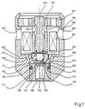
- the valve according to Fig. 1 features an armature 109 which is semi-spherical at its outer periphery; the armature is preferable machined from a sphere.
- the external diameter of the armature is preferably 5-6 mm.
- Armature 109 is flat at both top and bottom. Lateral guidance of the armature is provided by opening 123 which is part of housing 102. Because of the lateral guidance, and the flat shape at top and bottom, defined armature positioning is achieved at the termination of armature movement.
- Reset spring 110 is located inside armature 109.
- Pin 105 anchors reset spring 110. Pin 105 is pressure fitted into magnetic pole 101.
- Magnetic pole 101 is solidly connected to housing 102 through flange 107.
- the magnetic field is generated by coil 104.
- Magnetic return flow to armature 109 is via housing 102.
- the valve contains a diffuser 121 which is pressed into housing 102.
- Two flat valve seats 113 and 125 are machined into diffuser 121.
- Between valve seats 113 and 125 a circular groove 114 is disposed from which fuel flows to nozzles 118.
- Fuel flow to the sealing edges of the valve seats is via a pocket 116 and a hydraulic damping gap, or groove, 117 which are machined into diffuser 121.
- a preferred number of nozzles is 4-8.
- the direction of ejection of the nozzles is toward the inwards tapered edges 120 of diffuser 121.
- Straight line nozzles of this type are advantageous from a manufacturing point of view in comparison with the slanted arrangements otherwise in use. Furthermore, such vertically oriented nozzles allow for a specially narrow groove 114. By narrowing groove 114, the hydrostatic opening force exerted on armature 109 is reduced in advantageous manner.
- Fuel delivery is via orifices 103 in housing 102. From the housing the fuel flows via side orifices 106 to the internal region of pole 101, and from there via central passage 112 in armature 109 to the inside of valve seat 113. In addition, fuel passes via passages 108 to the outside of valve seat 113. Armature 109 may contain the additional side passages 111, which serve to equilibrate pressure between inner valve seat 125 and outer valve seat 113.
- valve seat shown in Fig.1 is perfused with fuel both on the inside and the outside, resulting in a large cross-sectional opening at small armature stroke. Electrical energy requirements of such valves with double sided valve seats are therefore distinctly lower than those of state of the art valves.
- the disadvantage versus state of the art valves is to be found in reduced tightness. This loss in tightness is caused by the fact that for seats of this type pocketing of the outer sealing edge is a possibility. Such pocketing of the outer sealing edge is caused by lopsided seating of the armature.
- pole 101 in Fig. 1 features collar 115 which juts out and provides the location against which armature 109 seals. This reduces the sealing surface of the armature.
- the use of such collars has already previously been proposed by applicant in an earlier application (P 34 08 012).
- the damping gaps according to the instant invention provide an additional advantage in the valve seat region, where a growing hydraulic reset force is established during the beginning of armature stroke. This increasing hydraulic reset force is generated by flow-forces in the damping gap. These flow-forces are initially only very small during valve opening, since at first the pressure drop almost exclusively happens in the valve seat. With progressing opening of the valve, the pressure drop in the damping gap surrounding the valve seat increases, causing the rise in hydraulic reset force. In addition, these hydraulic flow forces counteract any canting of the armature, resulting in an additional stabilizing effect on armature movement.
- damping gaps can be applied not only for groove type valve seats.
- the circular valve seat is simply surrounded by a damping gap.
- the use of such a simple circular valve seat is also possible for the valve described in Fig. 1, alternative to the groove-type valve seat described for it.
- damping gaps can be calculated numerically with the aid of simulation programs developed by the applicant. Nevertheless, a practically based optimization of the dimensions should be done, also in order to better assess the influence of the always present manufacturing tolerances. Experimental optimization can be done within the scope of the usual long term endurance test.
- the gap depth should be minimized as much as possible, without provoking significant delays in drop-off time of the armature caused by hydraulic damping forces. Valve drop-off times are easily measured by known methods.
- the width of collar 115 is also chosen to be as small as possible, without provoking pocketing of the closing surfaces during long term endurance tests. The beginning of pocketing is easily detected with the aid of a microscope.
- a functionally most favored height of the collar will be about 3-10 micrometers, and the width of the collar will be about 0.1-0.2 mm.
- the depth of the hydraulic damping gap 117, and the width of the outer valve seat are optimized by an analogous approach.
- the width of the inner valve seat should be as small as can be reliably achieved in manufacture (preferably about 0.1 mm).
- the depth of hydraulic damping gap 117 can be from 5 to 30 micrometers, where the larger values become a requirement for greater lateral extension of the pocket.
- a stamping procedure according to this invention is employed. To start with, the surfaces which are to hold damping gaps must be absolutely plane. Then a stamping tool is placed on the surface under consideration, and the damping gap is stamped in with the aid of an impact device.
- the damping gap is produced by a local densification of the material of which the item consists. Local densification excludes an otherwise possible uncontrolled spring-back of the material. Uncontrolled spring-back is always then a possibility if the part to be stamped is too thin-walled and is not firmly supported in the area where the stamping is to take place. Uncontrolled spring-back impairs the precision of the stamping process in an unacceptable manner.
- the depth of the damping gap is defined by the kinetic energy of the impact tool. The procedure is further explained with the aid of Fig. 2.
- Fig. 2 shows, by way of example, a suitable device to impress hydraulic damping gap 201 into magnetic pole 101 of the valve according to Fig. 1.
- magnet pole 101 is placed onto the massive pressure pad 203.
- the inert mass of 203 should be considerably larger than that of the work piece (pole 101).
- Stamping tool 205 is placed on the surface of pole 101 to be worked on.
- Stamping tool 205 is centered by guide sleeve 202 on pole 101.
- Stamping tool 205 is undercut at 209 to a larger depth than required for the damping gap. This guarantees that the stamping tool only contacts the area which is to be stamped.
- Lower edge 208 of the stamping tool is in the shape of the damping gap to be engraved, in this case an annular ring shape.
- Stamping tool 205 is spherical at its upper side. Above the stamping tool impact tool 207 is located. The depth of the stamping is given by the kinetic energy of impact tool 207, where the kinetic energy, in the case of simple impact devices, is directly proportional to the height of fall h. During the stamping process, impact tool 207 connects with contact point 206 of stamping tool 205. Given the ball-type surface 210 of stamping tool 205, contact point 206 is in the middle of the stamping device. This results in an even distribution of the impact force on surface 201 which is to be stamped. The even distribution of the impact force guarantees in simple fashion an extremely high precision of impact depth on the total circumference of the damping gap.
- stamping tool 205 can also be machined out of a hardened sphere. Using such spheres simplifies the manufacture of suitable stamping tools for rotationally symmetrical damping gap shapes.
- the procedure is not restricted to the fashioning of rotationally symmetrical damping gap shapes.
- the pressure point in this context, is defined as the point where the vertical axis of the stamping tool and the impact tool passes through the plane in which the damping gap is located (impact point of the kinetic force).
- the area center of gravity is always found in the center of the damping gap.
- the pressure point in this case would be chosen as the common area center of gravity of the damping gaps which are to be completed.
- the workpiece may, for instance, also be of oblong flat shape. Applicant introduces in a separate simultaneous application a valve with tilt-armature, where the tilt-armature, and the bearing for same, are of such oblong flat shapes.
- the stamping procedure introduced here is especially well suited for complicated parts of this type.
- FIG. 3 A top-view of magnet pole 101, which has been stamped with a damping gap by the stamping tool described in Fig. 2, is shown in Fig. 3.
- the stamping procedure according to the invention is exceptionally well suited for the manufacture of flat valve seats with narrow tolerances.
- the seating edge next to the damping gap is prepared directly by the stamping process for the damping gap. This will be further detailed with the aid of Fig. 4.
- Fig. 4 shows the valve seat according to Fig. 1 in top-view.
- the same reference numbers as in Fig. 1 are employed.
- the valve seat is supported by a pressure pad which fits into the central opening of diffuser 121 and engraves inner pocket 116.
- the complete diffuser 121 is supported by a flat pressure pad, and the hydraulic damping gap 117 is stamped in.
- Damping gap 117 should have a width of about 1-2 mm.
- Circular groove 114 is made by a separate working step.
- Both pocket 116 and damping gap 117 are then engraved together in one step.
- the stamping tool is then provided with an annular groove, in this fashion the inner and outer edges of this groove engrave the inner edge of valve seat 125 and the outer edge of outer valve seat 113.
- Stamping depth is preferably 5-30 micrometers.
- the stamping step may be followed by a brief lapping procedure to insure flatness; this should remove any possible distortions of the valve seats by the stamping step.
- the magnetic pole preferably has three contact surfaces 501, which are arranged equidistant on the circumference of the pole. Round or square contact surfaces are especially advantageous.
- the individual contact area segments should in each case be about 0.5-1 mm2. Damping gaps 502 are stamped in between contact areas 501. Contact areas 501 are shown cross-hatched.
- the hydraulic damping gap design shown in Fig. 5 is also suited for the manufacture of valve needle stops in state of the art injectors.
- Such state of the art valves feature a valve needle, guided in a central opening, which is solidly joined to the armature.
- the valve needle has an annular stop surface which closes against a disc-like stop for the open valve.
- damping gaps will be engraved into the disc-like stop.
- valve seat of this type will be detailed in connection with Fig. 6.
- Several hydraulic damping gaps, 602 are symmetrically arranged around seat 603. Centered in seat 603 is nozzle 604.
- the surface area 601 is reset by about 0.1-0.2 mm with respect to hydraulic damping gaps 602. This allows for largely unimpeded fuel flow to seat 603.
- Joint preparation of surface area 601 and the inside area 605 of valve seat 603 is preferably done by stamping.
- a lapping step of the total valve seat part, to insure planeness, follows.
- hydraulic damping gaps 602 are produced by a stamping tool which covers their area, and they are further stamped to a depth of about 3-10 micrometers with respect to the seat.
- FIG. 7 A further favorable valve seat design is shown in Fig. 7.
- a hydraulic damping gap 702 is arranged inside seat 701, the gap serves to attenuate armature impact.
- a further advantage of this seat design is an especially low fuel retention within the seat.
Landscapes
- Engineering & Computer Science (AREA)
- Chemical & Material Sciences (AREA)
- Combustion & Propulsion (AREA)
- Mechanical Engineering (AREA)
- General Engineering & Computer Science (AREA)
- Physics & Mathematics (AREA)
- Electromagnetism (AREA)
- Fuel-Injection Apparatus (AREA)
- Magnetically Actuated Valves (AREA)
- Forging (AREA)
Claims (6)
- Verfahren zur Herstellung von einem oder mehreren hydraulischen Dämpfungsspalten (117 oder 201) in einem einen Pol oder einen Ventilsitz enthaltenden Element (121 oder 101) eines elektromagnetischen Hydraulikventils, um das dynamische Ansprechverhalten des Ventiles zu verbessern, dadurch gekennzeichnet, daß der Spalt oder die Spalte durch Einstanzen der Oberfläche des Elementes (121 oder 101) mit einem Stanzwerkzeug (205, 207), das die Form der hydraulischen Dämpfungsspalte besitzt, erzeugt werden, was zu einer örtlichen Verdichtung des Materiales des Elementes führt, wobei die Tiefe der hydraulischen Dämpfungsspalte durch die kinetische Energie des Stanzwerkzeuges festgelegt wird.
- Verfahren nach Anspruch 1, dadurch gekennzeichnet, daß der Druckpunkt des Stanzwerkzeuges mit dem Mittelpunkt des Dämpfungsspaltes zusammenfällt (206).
- Verfahren nach Anspruch 1, dadurch gekennzeichnet, daß diverse koplanare Dämpfungsspalte (602) gleichzeitig hergestellt werden, wobei der Druckpunkt des Stanzwerkzeuges mit dem Mittelpunkt der Dämpfungsspalte zusammenfällt.
- Verfahren nach Anspruch 1, dadurch gekennzeichnet, daß das elektromagnetische Ventil einen oder mehrere Ventilsitze (113; 125) aufweist und daß das Verfahren einen Schritt umfaßt, bei dem mindestens ein Ventilsitzrand (113), der einem hydraulischen Dämpfungsspalt (117) nächstgelegen ist, mit dem Stanzwerkzeug gleichzeitig mit der Ausbildung der hydraulischen Dämpfungsspalte erzeugt wird.
- Verfahren nach Anspruch 1, dadurch gekennzeichnet, daß die hydraulischen Dämpfungsspalte bis zu einer Tiefe geformt werden, die 3/100 mm nicht übersteigt.
- Verfahren nach Anspruch 1, dadurch gekennzeichnet, daß die hydraulischen Dämpfungsspalte bis zu einer Tiefe geformt werden, die 1/100 mm nicht übersteigt.
Applications Claiming Priority (2)
| Application Number | Priority Date | Filing Date | Title |
|---|---|---|---|
| DE3834447A DE3834447A1 (de) | 1988-10-10 | 1988-10-10 | Elektromagnetisches einspritzventil und verfahren zu dessen herstellung |
| DE3834447 | 1988-10-10 |
Publications (2)
| Publication Number | Publication Date |
|---|---|
| EP0452329A1 EP0452329A1 (de) | 1991-10-23 |
| EP0452329B1 true EP0452329B1 (de) | 1994-02-16 |
Family
ID=6364780
Family Applications (1)
| Application Number | Title | Priority Date | Filing Date |
|---|---|---|---|
| EP89911462A Expired - Lifetime EP0452329B1 (de) | 1988-10-10 | 1989-10-10 | Verfahren zur Herstellung hydraulischer Dämpfungsspalten |
Country Status (6)
| Country | Link |
|---|---|
| US (1) | US5033716A (de) |
| EP (1) | EP0452329B1 (de) |
| JP (1) | JP2968295B2 (de) |
| KR (1) | KR960010291B1 (de) |
| DE (2) | DE3834447A1 (de) |
| WO (1) | WO1990004096A1 (de) |
Families Citing this family (38)
| Publication number | Priority date | Publication date | Assignee | Title |
|---|---|---|---|---|
| DE4018256A1 (de) * | 1990-06-07 | 1991-12-12 | Bosch Gmbh Robert | Elektromagnetisch betaetigbares brennstoffeinspritzventil |
| IT1250845B (it) * | 1991-10-11 | 1995-04-21 | Weber Srl | Valvola dosatrice e polverizzatrice di carburante ad azionamento elettromagnetico per un dispositivo di alimentazione di un motore endotermico |
| US5297915A (en) * | 1991-11-12 | 1994-03-29 | Bach Francis L | Apparatus for lifting and moving heavy objects |
| JPH05223031A (ja) * | 1992-02-12 | 1993-08-31 | Nippondenso Co Ltd | 燃料噴射弁 |
| US5307997A (en) * | 1993-03-12 | 1994-05-03 | Siemens Automotive L.P. | Fuel injector swirl passages |
| US5299776A (en) * | 1993-03-26 | 1994-04-05 | Siemens Automotive L.P. | Impact dampened armature and needle valve assembly |
| BR9406081A (pt) * | 1993-12-09 | 1996-02-06 | Bosch Gmbh Robert | Valvula acionável eletromagneticamente |
| JP3546508B2 (ja) * | 1994-03-25 | 2004-07-28 | 株式会社デンソー | インジェクターの製造方法及びインジェクタに用いられる可動コアの製造方法 |
| DE19544257B4 (de) * | 1995-11-28 | 2012-10-04 | Robert Bosch Gmbh | Elektromagnetisch betätigtes Ventil für hydraulische Bremsanlagen von Kraftfahrzeugen |
| US5954312A (en) * | 1996-01-31 | 1999-09-21 | Siemens Automotive Corporation | Groove means in a fuel injector valve seat |
| US5865371A (en) * | 1996-07-26 | 1999-02-02 | Siemens Automotive Corporation | Armature motion control method and apparatus for a fuel injector |
| US5758865A (en) * | 1996-08-21 | 1998-06-02 | Kavlico Corporation | Fuel injection valve and engine including the same |
| US6056214A (en) * | 1997-11-21 | 2000-05-02 | Siemens Automotive Corporation | Fuel injector |
| US6508418B1 (en) | 1998-05-27 | 2003-01-21 | Siemens Automotive Corporation | Contaminant tolerant compressed natural gas injector and method of directing gaseous fuel therethrough |
| US6328231B1 (en) | 1998-05-27 | 2001-12-11 | Siemens Automotive Corporation | Compressed natural gas injector having improved low noise valve needle |
| US6431474B2 (en) | 1999-05-26 | 2002-08-13 | Siemens Automotive Corporation | Compressed natural gas fuel injector having magnetic pole face flux director |
| US6405947B2 (en) * | 1999-08-10 | 2002-06-18 | Siemens Automotive Corporation | Gaseous fuel injector having low restriction seat for valve needle |
| US6422488B1 (en) * | 1999-08-10 | 2002-07-23 | Siemens Automotive Corporation | Compressed natural gas injector having gaseous dampening for armature needle assembly during closing |
| US6227457B1 (en) * | 1999-12-23 | 2001-05-08 | Siemens Automotive Corporation | Impact feature for an armature in a fuel injector |
| DE10105368A1 (de) * | 2001-02-06 | 2002-08-29 | Siemens Ag | Kraftstoffeinspritzdüse für eine Brennkraftmaschine |
| DE10148592A1 (de) * | 2001-10-02 | 2003-04-10 | Bosch Gmbh Robert | Brennstoffeinspritzventil |
| ITTO20010970A1 (it) * | 2001-10-12 | 2003-04-12 | Fiat Ricerche | Inettore di combustibile per un motore a combustione interna. |
| JP3719978B2 (ja) * | 2001-12-27 | 2005-11-24 | 株式会社日立製作所 | 燃料噴射弁 |
| DE10202722A1 (de) * | 2002-01-24 | 2003-11-27 | Siemens Ag | Düsenspannmutter für Einspritzventil sowie Verfahren zur Herstellung der Düsenspannmutter |
| DE10215980B4 (de) * | 2002-04-11 | 2008-03-27 | Siemens Ag | Leckageanschluss für einen Kraftstoffinjektor |
| JP4082929B2 (ja) * | 2002-05-21 | 2008-04-30 | 株式会社日立製作所 | 燃料噴射弁 |
| US20040011900A1 (en) * | 2002-05-22 | 2004-01-22 | Jens Gebhardt | Fuel injector assembly |
| US8382006B2 (en) * | 2002-05-22 | 2013-02-26 | Jens Gebhardt | Fuel injector assembly |
| US6702207B2 (en) * | 2002-07-16 | 2004-03-09 | Robert Bosch Gmbh | Fuel injector control module with unidirectional dampening |
| DE10256948A1 (de) * | 2002-12-05 | 2004-06-24 | Robert Bosch Gmbh | Brennstoffeinspritzventil |
| DE10325442A1 (de) * | 2003-06-05 | 2004-12-23 | Robert Bosch Gmbh | Magnetventil mit reduzierten Schaltgeräuschen |
| JP2006022727A (ja) * | 2004-07-08 | 2006-01-26 | Aisan Ind Co Ltd | 燃料噴射弁 |
| US7195226B2 (en) * | 2004-08-27 | 2007-03-27 | Kelsey-Hayes Company | Solenoid valve with spherical armature |
| DE102007046886B4 (de) * | 2007-09-28 | 2010-07-29 | Dieter Miehlich | EMS-Kleidungsstück und Elektrode sowie EMS-Modul dafür |
| US7509948B1 (en) | 2007-10-01 | 2009-03-31 | Caterpillar Inc. | Variable displacement pump with an anti-stiction device |
| JP4935882B2 (ja) * | 2009-03-05 | 2012-05-23 | 株式会社デンソー | 燃料噴射弁 |
| KR101345431B1 (ko) * | 2011-12-09 | 2013-12-27 | 주식회사 현대케피코 | 직분사 연료 인젝터 |
| US10364758B2 (en) | 2016-12-20 | 2019-07-30 | Continental Powertrain, USA, LLC | High pressure gas phase injector |
Family Cites Families (21)
| Publication number | Priority date | Publication date | Assignee | Title |
|---|---|---|---|---|
| FR1206142A (fr) * | 1957-05-10 | 1960-02-08 | Bendix Aviat Corp | Injecteur de combustible |
| US3001757A (en) * | 1958-04-09 | 1961-09-26 | Chrysler Corp | Magnetic fuel injection nozzle |
| DE1601395A1 (de) * | 1968-01-30 | 1970-10-29 | Bosch Gmbh Robert | Elektromagnetisch betaetigtes Einspritzventil |
| DE2049671A1 (de) * | 1970-10-09 | 1972-04-13 | Bosch Gmbh Robert | Magnetventil mit Maßnahmen gegen hydraulisches Kleben |
| US4245789A (en) * | 1979-05-03 | 1981-01-20 | General Motors Corporation | Electromagnetic fuel injector |
| DE3120160A1 (de) * | 1981-05-21 | 1982-12-09 | Robert Bosch Gmbh, 7000 Stuttgart | Elektromagnetisch betaetigbares ventil, insbesondere kraftstoffeinspritzventil fuer kraftstoffeinspritzan lagen |
| EP0102723A1 (de) * | 1982-07-29 | 1984-03-14 | LUCAS INDUSTRIES public limited company | Kraftstoffeinspritzventil nach Scheibenart |
| DE3312067A1 (de) * | 1983-04-02 | 1984-10-04 | Robert Bosch Gmbh, 7000 Stuttgart | Elektromagnetisch betaetigbares ventil |
| DE3408012A1 (de) * | 1984-03-05 | 1985-09-05 | Gerhard Dipl.-Ing. Warren Mich. Mesenich | Elektromagnetisches einspritzventil |
| IT1175561B (it) * | 1984-07-12 | 1987-07-01 | Spica Spa | Elettroiniettore perfezionato per alimentare combustibile a un motore a c.i. |
| JPS6179860A (ja) * | 1984-09-26 | 1986-04-23 | Hitachi Ltd | 電磁式燃料噴射弁 |
| DE3511463A1 (de) * | 1985-03-29 | 1986-10-09 | Robert Bosch Gmbh, 7000 Stuttgart | Elektromagnetisch betaetigbares ventil |
| EP0197232B1 (de) * | 1985-04-11 | 1989-06-28 | Honeywell Lucifer Sa | Impulsgesteuertes elektromagnetisches Ventil |
| DE3542044A1 (de) * | 1985-11-28 | 1987-06-04 | Gottfried Zimmermann | Verfahren und anwendung des verfahrens zum massivpraegen von profilierten mustern mittels einer presse |
| US4708117A (en) * | 1986-04-14 | 1987-11-24 | Colt Industries Inc. | Multi-point fuel injection apparatus |
| GB8611950D0 (en) * | 1986-05-16 | 1986-06-25 | Lucas Ind Plc | Gasoline injector |
| DE3641469C2 (de) * | 1986-12-04 | 1994-02-10 | Bosch Gmbh Robert | Elektromagnetisch betätigbares Kraftstoffeinspritzventil |
| DE3704541A1 (de) * | 1987-02-13 | 1988-09-01 | Vdo Schindling | Kraftstoff-einspritzventil |
| DE3723698C2 (de) * | 1987-07-17 | 1995-04-27 | Bosch Gmbh Robert | Kraftstoffeinspritzventil sowie Verfahren zu dessen Einstellung |
| GB2207463A (en) * | 1987-08-01 | 1989-02-01 | Lucas Ind Plc | I.C. engine petrol injector |
| DE3727342A1 (de) * | 1987-08-17 | 1989-03-02 | Bosch Gmbh Robert | Elektromagnetisch betaetigbares kraftstoffeinspritzventil |
-
1988
- 1988-10-10 DE DE3834447A patent/DE3834447A1/de not_active Withdrawn
-
1989
- 1989-10-10 KR KR1019900701240A patent/KR960010291B1/ko not_active Expired - Fee Related
- 1989-10-10 US US07/419,376 patent/US5033716A/en not_active Expired - Lifetime
- 1989-10-10 DE DE68913215T patent/DE68913215T2/de not_active Expired - Fee Related
- 1989-10-10 JP JP1510705A patent/JP2968295B2/ja not_active Expired - Fee Related
- 1989-10-10 WO PCT/US1989/004324 patent/WO1990004096A1/en not_active Ceased
- 1989-10-10 EP EP89911462A patent/EP0452329B1/de not_active Expired - Lifetime
Also Published As
| Publication number | Publication date |
|---|---|
| KR960010291B1 (ko) | 1996-07-27 |
| DE68913215D1 (de) | 1994-03-24 |
| JP2968295B2 (ja) | 1999-10-25 |
| KR900702216A (ko) | 1990-12-06 |
| US5033716A (en) | 1991-07-23 |
| WO1990004096A1 (en) | 1990-04-19 |
| DE3834447A1 (de) | 1990-04-12 |
| DE68913215T2 (de) | 1994-07-14 |
| EP0452329A1 (de) | 1991-10-23 |
| JPH04505197A (ja) | 1992-09-10 |
Similar Documents
| Publication | Publication Date | Title |
|---|---|---|
| US5033716A (en) | Electromagnetic fuel injector | |
| CA1124601A (en) | Electromagnetic fuel injector with selectively hardened armature | |
| US6035532A (en) | Groove means in a fuel injector valve seat | |
| EP1264984A1 (de) | Modulares Brennstoffeinspritzventil und sein Zusammenbau | |
| JP3069752B2 (ja) | 電磁式内燃機関燃料噴射装置 | |
| US4247052A (en) | Electromagnetic fuel injector | |
| EP0446214A1 (de) | Elektromagnetisch betätigbares kraftstoff-einspritzventil mit einer membranfeder. | |
| EP0826106A1 (de) | Ankerführung für ein elektromechanisches kraftstoffeinspritzventil und zusammenbaumethode | |
| EP2749800B1 (de) | Magnetventil | |
| WO1993002285A1 (de) | Brennstoffeinspritzventil | |
| US7021569B1 (en) | Fuel injection valve | |
| US8261446B2 (en) | Injector seat that includes a coined seal band with radius | |
| KR20000071199A (ko) | 연료 분사 밸브용 밸브 시트체의 제조 방법 및 연료 분사 밸브 | |
| US6687997B2 (en) | Method of fabricating and testing a modular fuel injector | |
| US6708906B2 (en) | Modular fuel injector having a surface treatment on an impact surface of an electromagnetic actuator and having an integral filter and dynamic adjustment assembly | |
| JPH04507122A (ja) | 電磁式に操作される燃料噴射弁 | |
| EP1219815A1 (de) | Modulares Brennstoffeinspritzventil mit einer den Hub einstellenden Hülse | |
| JP2004036604A (ja) | オフセット圧印加工斜角オリフィスを有するオリフィスプレートを備えた燃料噴射器 | |
| EP1668241B1 (de) | Ein angepresstes dichtungsband enthaltender injektorsitz | |
| US5626295A (en) | Injection valve | |
| US5056754A (en) | Electromagnetically actuatable valve | |
| KR960013106B1 (ko) | 전자 밸브 | |
| EP0215527A1 (de) | Elektromagnetisches Brennstoffeinspritzventil für Verbrennungsmotoren und dessen Herstellungsverfahren | |
| US20250116249A1 (en) | Magnet assembly for a fuel injector, and fuel injector | |
| JPH04365305A (ja) | ソレノイド用ステータ |
Legal Events
| Date | Code | Title | Description |
|---|---|---|---|
| PUAI | Public reference made under article 153(3) epc to a published international application that has entered the european phase |
Free format text: ORIGINAL CODE: 0009012 |
|
| 17P | Request for examination filed |
Effective date: 19910806 |
|
| AK | Designated contracting states |
Kind code of ref document: A1 Designated state(s): DE FR GB IT |
|
| RIN1 | Information on inventor provided before grant (corrected) |
Inventor name: MESENICH, GERHARD, DIPL.-ING. |
|
| 17Q | First examination report despatched |
Effective date: 19920302 |
|
| GRAA | (expected) grant |
Free format text: ORIGINAL CODE: 0009210 |
|
| AK | Designated contracting states |
Kind code of ref document: B1 Designated state(s): DE FR GB IT |
|
| REF | Corresponds to: |
Ref document number: 68913215 Country of ref document: DE Date of ref document: 19940324 |
|
| ITF | It: translation for a ep patent filed | ||
| ET | Fr: translation filed | ||
| PLBE | No opposition filed within time limit |
Free format text: ORIGINAL CODE: 0009261 |
|
| STAA | Information on the status of an ep patent application or granted ep patent |
Free format text: STATUS: NO OPPOSITION FILED WITHIN TIME LIMIT |
|
| 26N | No opposition filed | ||
| REG | Reference to a national code |
Ref country code: GB Ref legal event code: IF02 |
|
| PGFP | Annual fee paid to national office [announced via postgrant information from national office to epo] |
Ref country code: GB Payment date: 20021010 Year of fee payment: 14 |
|
| PGFP | Annual fee paid to national office [announced via postgrant information from national office to epo] |
Ref country code: FR Payment date: 20021023 Year of fee payment: 14 |
|
| PGFP | Annual fee paid to national office [announced via postgrant information from national office to epo] |
Ref country code: DE Payment date: 20021216 Year of fee payment: 14 |
|
| PG25 | Lapsed in a contracting state [announced via postgrant information from national office to epo] |
Ref country code: GB Free format text: LAPSE BECAUSE OF NON-PAYMENT OF DUE FEES Effective date: 20031010 |
|
| PG25 | Lapsed in a contracting state [announced via postgrant information from national office to epo] |
Ref country code: DE Free format text: LAPSE BECAUSE OF NON-PAYMENT OF DUE FEES Effective date: 20040501 |
|
| GBPC | Gb: european patent ceased through non-payment of renewal fee |
Effective date: 20031010 |
|
| PG25 | Lapsed in a contracting state [announced via postgrant information from national office to epo] |
Ref country code: FR Free format text: LAPSE BECAUSE OF NON-PAYMENT OF DUE FEES Effective date: 20040630 |
|
| REG | Reference to a national code |
Ref country code: FR Ref legal event code: ST |
|
| PG25 | Lapsed in a contracting state [announced via postgrant information from national office to epo] |
Ref country code: IT Free format text: LAPSE BECAUSE OF NON-PAYMENT OF DUE FEES Effective date: 20051010 |