EP0452466B1 - Automatische fehlererholung in einem paketnetz - Google Patents
Automatische fehlererholung in einem paketnetz Download PDFInfo
- Publication number
- EP0452466B1 EP0452466B1 EP90916903A EP90916903A EP0452466B1 EP 0452466 B1 EP0452466 B1 EP 0452466B1 EP 90916903 A EP90916903 A EP 90916903A EP 90916903 A EP90916903 A EP 90916903A EP 0452466 B1 EP0452466 B1 EP 0452466B1
- Authority
- EP
- European Patent Office
- Prior art keywords
- virtual
- network node
- fault
- circuit
- affected
- Prior art date
- Legal status (The legal status is an assumption and is not a legal conclusion. Google has not performed a legal analysis and makes no representation as to the accuracy of the status listed.)
- Expired - Lifetime
Links
- 238000011084 recovery Methods 0.000 title description 19
- 230000005540 biological transmission Effects 0.000 claims abstract description 23
- 238000000034 method Methods 0.000 claims description 9
- 238000001514 detection method Methods 0.000 claims 4
- 238000003780 insertion Methods 0.000 claims 1
- 230000037431 insertion Effects 0.000 claims 1
- 238000013507 mapping Methods 0.000 description 14
- 238000010586 diagram Methods 0.000 description 4
- 102100025708 Choline/ethanolaminephosphotransferase 1 Human genes 0.000 description 1
- 101000914238 Homo sapiens Choline/ethanolaminephosphotransferase 1 Proteins 0.000 description 1
- 230000003213 activating effect Effects 0.000 description 1
- 230000004913 activation Effects 0.000 description 1
- 238000009432 framing Methods 0.000 description 1
- 238000012544 monitoring process Methods 0.000 description 1
- 230000011664 signaling Effects 0.000 description 1
Images


Classifications
-
- H—ELECTRICITY
- H04—ELECTRIC COMMUNICATION TECHNIQUE
- H04L—TRANSMISSION OF DIGITAL INFORMATION, e.g. TELEGRAPHIC COMMUNICATION
- H04L12/00—Data switching networks
- H04L12/54—Store-and-forward switching systems
- H04L12/56—Packet switching systems
Definitions
- This invention relates to packet transmission systems and/or networks and, more particularly, to automatic recovery from faults in the system and/or network.
- Prior packet transmission and switching systems and/or networks included fault recovery arrangements.
- One such prior arrangement required a so-called centralized network management function to analyze reported faults and to reconfigure the network as required. Consequently, the centralized network management function required knowledge of the entire network and connectivity to each node in the network. Such arrangements are slow to respond to faults and are also susceptible to faults in the network and in the management function itself.
- a transmission system that employs a master station to issue a fault location command to all the other stations in the system is disclosed in US-A-4855993.
- each node in the network required knowledge of the network configuration and knowledge of faults occurring in the network.
- each node must store additional network configuration data other than that needed for transmission of packets in the particular node. Any change in the network configuration may require a change in the information being stored in the node. Both the storing and updating of the configuration information in the node is cumbersome and expensive to implement.
- a node receiving such a fault indication message determines whether the corresponding virtual circuit is terminated, i.e., exits the network, at the node or passes through this node to some other unknown node in the network. If an affected virtual circuit is terminated in the node, it is switched to an alternate virtual circuit. If an affected virtual circuit is not terminated in the node, the corresponding received fault indication message is passed through the node on that virtual circuit to the some other unknown node.
- FIG. 1 shows, in simplified form, details of transmission system and/or network 100 employing an embodiment of the invention. Accordingly, shown are a plurality of system and/or network nodes, namely, nodes 101-1 through 101-N. Hereinafter all references will be made to network nodes, etc. Also shown are a number of network facilities (NFs) connecting nodes 101 and access facilities (AFs) connected to particular ones of nodes 101. Network facilities carry virtual links (VLs) between nodes inside the network. Access facilities carry access circuits from the network to outside of the network and, conversely, from outside of the network to the network. In this example, some of nodes 101 are identical and others are not depending on their particular function in the network.
- NFs network facilities
- AFs access facilities
- VLs virtual links
- nodes 101 have access facilities connected to them while others do not. It will also be apparent that particular ones of nodes 101 may have a plurality of access facilities. Similarly, particular ones of nodes 101 may interface with a plurality of network facilities connecting them to one or more other nodes.
- the network facilities are either T1, CEPT1, or T3 transmission facilities using non-channelized ISDN packet mode framing formats, e.g., LAPD, protocols, and procedures. In some different applications, other facilities may be employed, for example, local area networks, wide area networks, RS232 and the like. Each network facility carries one or more virtual links.
- the access facilities are assumed to be T1 or ISDN basic rate interface (BRI) facilities.
- Each access facility carries one or more access circuits.
- an access circuit may be connected to a virtual link or a virtual link may be connected to another virtual link.
- a virtual circuit for a call comprises a local access circuit, one or more virtual links connected through one or more nodes and at least one remote access circuit. It will be apparent to those skilled in the art that other transmission facilities and other packet protocols may equally be employed in practicing the invention.
- a primary virtual circuit shown in dashed outline, is provisioned between an access circuit carried on the access facility (AF) shown connected to node 101-1 and an access circuit carried on the access facility (AF) shown connected to node 101-N.
- the primary virtual circuit is carried from originating node 101-1 to destination node 101-N through a primary path including nodes 101-2, 101-3 and 101-4 and virtual links (VLs) carried on the associated network facilities (NFs).
- VLs virtual links
- an alternate virtual circuit shown in dot-dashed outlined, is provisioned between the access circuit carried on the access facility (AF) connected to node 101-1 and the access circuit carried on the access facility (AF) connected to node 101-N on an alternate path passing through node 101-5 and virtual links carried on the associated network facilities (NFs).
- NFs network facilities
- node 101-1 and node 101-N there may be a plurality of such virtual circuits between node 101-1 and node 101-N.
- none of nodes 101 in network 100 has knowledge of any other node in the network.
- Each of nodes 101 only knows its own mappings of access circuits to virtual links and virtual links to virtual links.
- a fault can occur in the node equipment itself or in one or more network facilities connecting nodes. In this example, it is assumed that a fault occurs somewhere in the transmission path between nodes 101-3 and 101-4.
- each of nodes 101-3 and 101-4 determines that a particular virtual circuit, among others, is affected by the fault.
- Node 101-3 generates a fault indication message and supplies it as an output on the affected virtual circuit to node 101-2.
- the fault indication message is a LAPD frame (FIGs.
- node 101-4 uses a XID format (See CCITT Recommendation Q.921, pages 42-48, and a Committee T1 Contribution, "Explicit Congestion avoidance indication as part of Link Layer management", T1S1.1-89/339, T1S1.2-89/240, July 17-19, 1989, pages 1-14 for an explanation of the LAPD frame and XID format).
- node 101-4 generates a fault indication message and supplies it as an output on the affected virtual circuit to node 101-N.
- nodes 101-3 and 101-4 include information relating only to the virtual link to virtual link mapping of the virtual circuit.
- node 101-2 Upon receiving the fault indication message, node 101-2 determines whether the affected virtual circuit is terminated at this node. Since the fault indication message does not apply to a virtual circuit terminated in node 101-2, it relays the fault indication message on the virtual link of the affected virtual circuit passing through the network facility connecting node 101-2 to node 101-1. In this example, this relaying of the fault indication message is realized by employing the known LAPD frame relay procedures. (See articles entitled “Frame Relay: Protocols and Private Network Applications", Proceedings IEEE INFOCOM 89 , April 23-27, 1989, pages 676-685 and "Frame Relaying Service: An Overview", Proceedings IEEE INFOCOM 89 , April 23-27, 1989, pages 668-673 for an explanation of frame relay).
- node 101-1 When node 101-1 receives the fault indication message it determines that the fault indication message applies to a virtual circuit that is terminated at this node. Then, node 101-1 switches the virtual circuit from its primary path that was disrupted by the fault to its alternate path that passes through node 101-5. Similar actions to those effected in node 101-1 are taken by node 101-N upon receiving the fault indication message that was originated by node 101-4.
- the network has recovered from the fault on the affected virtual circuit. Furthermore, it can be seen that, in accordance with an aspect of the invention, this recovery is accomplished without any node having information relating to the network topology other than for the network facilities that terminate at individual ones of nodes 101.
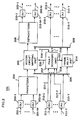
- FIG. 2 shows, in simplified block diagram form, the general architecture of nodes 101.
- the configuration of specific ones of nodes 101 may include an interface to at least one network facility and may not include any access facilities.
- a typical one of nodes 101 includes one or more receive access facilities 201-1 through 201-M, and a corresponding number of transmit access facilities 202-1 through 202-M.
- the signals received and transmitted on the access links may take any desired form.
- the access facility signals are non-packetized T-carrier in the known DS1 format.
- an access facility carries up to 24 access circuits.
- Signals obtained from receive access facilities 201-1 through 201-M are supplied via digital line interface (DLI) units 203-1 through 203-M, respectively, to packetizer 204.
- Each of digital line interfaces 203 are of a type well known in the art for interfacing the DS 1 signals being supplied via the receive access facilities 201.
- Packetizer 204 forms incoming voice or data information into a packet format. Such packetizers are known in the art.
- the LAPD format is used for packetization.
- the LAPD layer 2 data unit is known as a frame
- the layer 3 data unit is known as a packet.
- the term "frame" is used instead of "packet”.
- the LAPD frames (FIG. 9) generated in packetizer 204 are supplied to access circuit mapping unit 205.
- Access circuit mapping unit 205 also obtains received frames from receive frame bus 206.
- remap control signals are supplied to access circuit mapping unit 205 via circuit path 220 from fault recovery unit 207.
- the remap control signals control remapping of access circuits carried on receive access facitilies 201 to virtual links carried on transmit network facilities 212, and the remapping of virtual links carried on receive network facilities 211 to the original access circuits carried on transmit access facilities 202.
- Access circuit mapping unit 205 yields so-called terminated frames which are supplied to depacketizer 208, and so-called transmit frames which are supplied to transmit frame bus 209.
- Depacketizer 208 reconstructs the voice or data digital signals from the terminated LAPD frames. These signals are supplied via digital line interface (DLI) units 210-1 through 210-M to transmit access facilities 202-1 through 202-M, respectively. Again, such digital line interface units and such depacketizers are known in the art.
- DLI digital line interface
- Received LAPD frames from receive network facilities 211-1 through 211-Y are supplied to digital line interface (DLI) units 213-1 through 213-Y, respectively.
- Each of digital line interface units 213 is of a type well known in the art for interfacing DS1 digital signals.
- each of digital line interface (DLI) units 213 generates a facility failure signal in well known fashion.
- the facility failure signals from digital line interfaces 213-1 through 213-Y each indicate whether a red, yellow, blue, or performance alarm has occurred and are supplied via circuit paths 217-1 through 217-Y, respectively, to fault recovery unit 207.
- Each of digital line interface units (DLI) 213-1 through 213-Y supplies the received LAPD frames to receive frame bus 206.
- the received frames can be of many types, including received fault indication messages as shown in FIGs. 10 and 11.
- Fault recovery unit 207 obtains the received fault indication messages from receive frame bus 206 via circuit path 218, in well known fashion.
- An equipment failure signal indicating the failure of any unit in this node in the path of any virtual circuit is supplied via circuit path 216 to fault recovery unit 207.
- Fault recovery unit 207 generates transmit fault indication messages which are supplied via circuit path 219 to transmit frame bus 209 and receive fault indication messages which are supplied via circuit path 221 to frame relay unit 214.
- Frame relay unit 214 obtains the received frames from receive frame bus 206. Additionally, frame relay unit 214 relays transmit frames from receive frame bus 206 to transmit frame bus 209.
- frame relay unit 214 employs the known frame relay procedure to remap these incoming frames into transmit frames that are supplied to transmit frame bus 209.
- the relayed frames include appropriate address mapping for each virtual circuit. That is to say, LAPD frames that are passing through this node are frame relayed from receive frame bus 206 to transmit frame bus 209.
- the operation of frame relay unit 214 is described below in conjunction with FIG. 7.
- the appropriate transmit frames are obtained from transmit frame bus 209 by digital line interface units 215-1 through 215-Y and, then, supplied to transmit network facilities 212-1 through 212-Y, respectively. Pairs of receive network facilities 211-1 through 211-Y and transmit network facilities 212-1 through 212-Y form the network facilities (NFs) shown in FIG. 1.
- Fault recovery unit 207 monitors for fault indication messages (FIGs. 10 and 11) on receive frame bus 206. This is achieved by monitoring received frames for those that match a prescribed format. To this end, control fields in the received frames are monitored to determine if the frames include a fault indication message.
- the prescribed format is the so-called LAPD XID frame format denoting fault indication messages for either a fault condition or a clear condition, as shown in FIG. 10 and FIG. 11, respectively. As shown in both FIG. 10 and FIG.
- the affected virtual circuit ID is included in the DLCI fields, an indication (in this example, 10101111) that the LAPD frame is an XID frame is included in the XID field, an indication that this XID frame is a fault indication message, in accordance with an aspect of the invention, is included in the FI field and an indication, in accordance with an aspect of the invention, of whether the fault indication message denotes a fault or clear condition is included in the GI field.
- the indication 11111010 in the GI field denotes a fault condition
- the indication 11110000 in the GI field denotes a clear condition.
- fault recovery unit 207 Upon obtaining a fault indication message, fault recovery unit 207 either sends a remap control signal to access circuit mapping unit 205 causing it to switch a corresponding access circuit to a virtual link included in the alternate virtual circuit, in accordance with an aspect of the invention, or sends a corresponding receive fault indication message via circuit path 221 to frame relay unit 214. In turn, frame relay unit 214 supplies the fault indication message to another node on a virtual link included in the primary virtual circuit.
- fault recovery unit 207 monitors for facility or equipment failures, and either orders access circuit mapping unit 205 via remap control signals to switch the affected access circuits to alternate virtual circuits and/or generates transmit fault indication messages to be passed via transmit frame bus 209 and appropriate ones digital line interface (DLI) units 215-1 through 215-Y and transmit network facilities 212-1 through 212-Y, respectively, to other ones of nodes 101 in network 100 (FIG.1). Further details regarding operation of fault recovery unit 207 are discussed below in conjunction with FIGs. 3 through 6.
- DLI digital line interface
- FIG. 3 depicts, in simplified block diagram form, details of fault recovery unit 207 of FIG. 2. Accordingly, shown are fault indication message receiver 301 and fault indication message generator 302.
- Fault indication message receiver 301 obtains received fault indication messages via circuit path 218 from receive frame bus 206. If the received fault indication message is for an access circuit in this node, the remap control signal for that access circuit is activated. If a received fault indication message is not for an access circuit in this node, it is supplied as an output unchanged to frame relay unit 214. The operation of fault indication message receiver 301 is shown in the flow chart of FIG. 4 and described below.
- Fault indication message generator 302 is responsive to either a facility failure signal or an equipment failure signal becoming active or inactive.
- fault indication message generator 302 determines if the failure affects an access circuit terminated in this node. If an access circuit terminated in this node is affected, a remap control signal for the access circuit is activated. If the affected access circuit is not in this node, a transmit fault indication message including a fault indication (FIG. 10) is generated for the affected access circuit. Similarly, when the fault is cleared, either the remap control signal is deactivated or a transmit fault indication message including a clear indication (FIG. 11) is generated. Operation of fault indication message generator 302 is described below in conjunction with the flow chart shown in FIGs. 5 and 6.
- FIG. 4 is a flow chart showing a sequence of operations effected in fault indication message receiver 301 of FIG. 3. Accordingly, the sequence is entered via step 401. Thereafter, conditional branch point 402 tests to determine if there is a received fault indication message on receive frame bus 206 (FIG. 2). If the test result is NO, the sequence is exited via step 403. If the test result in step 402 is YES, operational block 404 determines the virtual link identification corresponding to the obtained fault indication message. In the LAPD format this identification (ID) is known as the DLCI. Then, conditional branch point 405 tests to determine if the determined virtual link ID (DLCI) is mapped to an access circuit in this node.
- ID the virtual link identification
- step 405 If the test result in step 405 is NO, the virtual link denoted by this DLCI is frame relayed via frame relay unit 214 (FIG. 2) through this node. To this end, operational block 406 supplies as an output the received fault indication message to frame relay unit 214 (FIG. 2). Thereafter, the sequence is exited via step 403. If the test result in step 405 is YES, the virtual link denoted by this DLCI is mapped to an appropriate access circuit in this node, i.e., the virtual circuit is terminated at this node. Conditional branch point 407 tests to determine that the received fault indication message indicates the activating of a fault or the clearing of a fault.
- test block 408 supplies as an output an activated remap control signal for this virtual link ID (DLCI) to access circuit mapping unit 205 (FIG. 2). Thereafter, the sequence is exited via step 403.
- test result in step 407 is NO, indicating clearing of a fault
- operational block 409 supplies as an output a deactivated remap control signal for this virtual link ID (DLCI) to access circuit mapping unit 205 (FIG. 2). Thereafter, the sequence is exited via step 403.
- steps 402 and 404 through 406 could be reversed in order such that steps 404 and 405 are performed for all received frames and if the test result in step 405 is YES, then step 402 is performed to determine if the received frame includes a fault indication message.
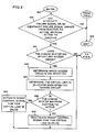
- conditional branch point 505 If the test result in step 504 is NO, control is supplied to conditional branch point 505 (FIG. 6). If the test result in step 504 is YES, operational block 506 determines which access circuits are affected. It is noted that more than one access circuit may be affected. Then, operational block 507 determines the virtual link ID (DLCI) for each affected access circuit. Conditional branch point 508 tests to determine if the change in state of either failure signal is from inactive to active. If the test result in step 508 is YES, operational block 509 activates the remap control signal for this virtual link ID (DLCI). Then, control is supplied to conditional branch point 505.
- DLCI virtual link ID
- step 508 If the test result in step 508 is NO, operational block 510 deactivates the remap control signal for this virtual link ID (DLCI). Thereafter, control is supplied to conditional branch point 505 (FIG. 6). Conditional branch point 505 tests to determine if the change in state of either failure signal affects any so-called frame relay connection, i.e., virtual link to virtual link connection. It is noted that an affected frame relay connection includes a faulted or cleared virtual link and a connected virtual link. If the test result in step 505 is NO, the sequence is exited via step 503 (FIG. 5). If the test result in step 505 is YES, operational block 511 determines which frame relay connections are affected by the fault.
- DLCI virtual link ID
- Operational block 512 determines the virtual link ID (DLCI) and the network facility of the connected virtual link for each affected virtual link.
- Operational block 513 generates a fault indication message for each affected frame relay connection using the virtual link ID (DLCI) that was determined in step 512 as an address.
- Conditional branch point 514 tests to determine whether the change in state of either failure signal is from inactive to active. If the test result in step 514 is YES, operational block 515 causes the fault indication message generated in block 513 to indicate "fault" (FIG. 10). If the test result in step 514 is NO, operational block 516 causes the fault indication message generated in block 513 to indicate "clear" (FIG. 11). Thereafter, operational block 517 supplies as an output the fault indication messages to transmit frame bus 209 (FIG. 2). Then, the sequence is exited via step 503 (FIG. 5).
- DLCI virtual link ID
- Operational block 513 generates a fault indication message for each affected frame relay connection using the virtual link
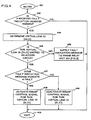
- FIG. 7 is a flow chart of a sequence of operations effected by access circuit mapping unit 205 of FIG. 2. Accordingly, the sequence is entered via step 701. Thereafter, conditional branch point 702 tests to determine if a received frame is present on receive frame bus 206 (FIG. 2). If the test result in step 702 is YES, operational block 703 determines the virtual link ID (DLCI) for the received frame. Conditional Branch point 704 tests to determine if the remap control signal is active for this virtual link ID (DLCI). If the test result in 704 is YES, operational block 705 causes the virtual link ID (DLCI) determined in step 703 to be modified to a DLCI for the appropriate virtual link ID of the primary virtual circuit.
- DLCI virtual link ID
- test result in step 704 is NO, no action is taken to change the virtual link ID (DLCI) and operational block 706 supplies the received frame to depacketizer 208 (FIG. 2). Thereafter, the sequence is exited via step 707.
- conditional branch point 708 tests to determine if there is a generated frame from packetizer 204 (FIG. 2). If the test result in step 708 is NO, the sequence is exited via step 707. If the test result in step 708 is YES, operational block 709 determines the virtual link ID (DLCI) for the generated frame. Then, conditional branch point 710 tests to determine if the remap control signal is active for this virtual link ID (DLCI).
- operational block 711 changes the virtual link ID (DLCI) in the generated frame to the alternate virtual link ID (DLCI) for the appropriate virtual link in the alternate virtual circuit (FIG. 1). Then, operational block 712 supplies as an output the generated frame to transmit frame bus 209 (FIG. 2). Thereafter, the sequence is exited via step 707.
- the test result is NO, the generated frame DLCI is not changed and steps 712 and 707 are iterated.
- FIG. 8 is a flow chart of a sequence of operations effected in frame relay unit 214 of FIG. 2. This flow chart does not completely describe the LAPD frame relay function known to the art but only those functions necessary to this embodiment of the invention. Accordingly, the sequence is entered via step 801. Then, conditional branch point 802 tests to determine if there is a received frame on receive frame bus 206 (FIG. 2). If the test result in step 802 is NO, conditional branch point 803 tests to determine if there is a receive fault indication message on receive frame bus 206 (FIG. 2). If the result in step 803 is NO, the sequence is exited via step 804.
- operational block 805 determines the virtual link ID (DLCI) for the received frame.
- Operational block 806 determines the virtual link ID (DLCI) for the connected virtual link, i.e., the frame relay connection.
- Operational block 807 changes the virtual link ID (DLCI) of the received frame to the virtual link ID (DLCI) for the connected virtual link.
- Operational block 808 supplies as an output the modified "received" frame to the transmit frame bus 209 (FIG. 2). Thereafter, the sequence is exited by step 804.
Landscapes
- Engineering & Computer Science (AREA)
- Computer Networks & Wireless Communication (AREA)
- Signal Processing (AREA)
- Data Exchanges In Wide-Area Networks (AREA)
Claims (14)
- Vorrichtung zur Verwendung in einem Netzwerkknoten (z.B. 101-1) für die Wiedererlangung der Betriebsfähigkeit nach Fehlern auf Übertragungswegen einschließlich wenigstens eines virtuellen Stromkreises, wobei der Netzwerkknoten zur Verwendung in einem Netzwerk mit einer Vielzahl solcher Knoten bestimmt ist und jeder Netzwerkknoten eine Einrichtung (DLls 213-1, 213-Y) zur Feststellung von Fehlern auf wenigstens einem, an den Netzwerkknoten angeschlossenen Übertragungsweg (211-1, 211-Y) enthält und der virtuelle Stromkreis eine erste Zugriffsschaltung an einem Ursprungsnetzwerkknoten, eine zweite Zugriffsschaltung an einem Bestimmungsnetzwerkknoten und wenigstens eine virtuelle Linkleitung umfaßt,
dadurch gekennzeichnet, daß
der Netzwerkknoten keine Information bezüglich der Netzwerktopologie außer für die Netzwerkeinrichtungen besitzt, die an den Netzwerkknoten angeschlossen sind,
daß ein Fehleranzeigenachrichtengenerator (302 über 513) zur Erzeugung einer Fehleranzeigenachricht für jeden, durch den festgestellten Fehler beeinträchtigten virtuellen Stromkreis aufweist, der nicht an den Netzwerkknoten angeschlossen ist, einschließlich einer Detektoreinrichtung (302 über 502, 504, 506, 507) zur Feststellung derjenigen virtuellen Stromkreise, die an den Netzwerkknoten angeschlossen und durch den festgestellten Fehler beeinträchtigt sind und zur Feststellung (302 über 502, 504, 505, 511, 512) derjenigen virtuellen Stromkreise, die nicht an das Netzwerk angeschlossen sind und durch den festgestellten Fehler beeinträchtigt werden,
daß ferner eine Übertragungseinrichtung (302 über 517, 209) vorgesehen ist, die jede erzeugte Fehleranzeigennachricht auf ihrem zugeordneten virtuellen Stromkreis weg vom Fehler zu einem anderen Netzwerkknoten im Netzwerk überträgt, und
daß eine Vermittlungseinrichtung (205, 209) vorgesehen ist, um die festgestellten, beeinträchtigten, virtuellen Stromkreise, die an den Netzwerkknoten angeschlossen sind, auf zugeordnete, alternative, virtuelle Stromkreise für eine Übertragung in Richtung zu einem Bestimmungsnetzwerkknoten umzuschalten. - Vorrichtung nach Anspruch 1 mit ferner einem Empfänger (301) zum Empfang von Fehleranzeigenachrichten einschließlich einer Detektoreinrichtung (301 über 402, 404, 405) zur Feststellung, ob ein in einer empfangenen Fehleranzeigenachricht identifizierter virtueller Stromkreis an den Netzwerkknoten angeschlossen ist, und eine Übertragungseinrichtung (301 über 406, 214) zur Übertragung jeder empfangenen Fehleranzeigenachricht, die nicht einem virtuellen, an den Netzwerkknoten angeschlossenen Stromkreis zugeordnet ist, über ihren zugeordneten virtuellen Stromkreis zu einem anderen Netzwerkknoten im Netzwerk.
- Vorrichtung nach Anspruch 3, bei der die empfangene Fehleranzeigenachricht die Identität einer virtuellen Linkleitung auf dem virtuellen Stromkreis enthält, über den übertragen wird, und die Detektoreinrichtung im Empfänger einen Steuersignalgenerator (301 über 402, 404-409) zur Erzeugung eines Steuersignals aufweist, das angibt, ob die in der empfangenen Fehleranzeigenachricht identifizierte, virtuelle Linkleitung einer Zugriffsschaltung im Netzwerkknoten zugeordnet ist, und wobei die Vermittlungseinrichtung (205, 209) unter Ansprechen auf das Steuersignal die Identität der virtuellen Linkleitung in eine alternative Identität einer virtuellen Linkleitung ändert, wenn das Steuersignal anzeigt (über 408), daß die virtuelle Linkleitung einer Zugriffsschaltung im Netzwerkknoten zugeordnet ist, wobei die Zugriffsschaltung einem alternativen virtuellen Stromkreis zur Übertragung an die Zugriffsschaltung im Bestimmungsnetzwerkknoten zugeordnet ist.
- Vorrichtung nach Anspruch 2, bei der die Detektoreinrichtung im Fehleranzeigenachrichtengenerator eine Identifiziereinrichtung (302 über 504, 505) zur Identifizierung von Zugriffsschaltungen im Netzwerkknoten aufweist, die durch den festgestellten Fehler beeinträchtigt sind, ferner eine Identifiziereinrichtung (302 über 507) für virtuelle Linkleitungen zur Identifizierung einer zugeordneten virtuellen Linkleitung für jede Zugriffsschaltung im Netzwerkknoten, welche durch den festgestellten Fehler beeinträchtigt ist, und einen Steuersignalgenerator (302 über 508-510) zur Erzeugung eines ersten Steuersignals, das angibt, daß eine entsprechende Zugriffsschaltung einer virtuellen, durch den festgestellten Fehler beeinträchtigten Linkleitung zugeordnet ist, wobei die Vermittlungseinrichtung eine Identifizieränderungseinrichtung (205 über 708-711) enthält, die unter Ansprechen auf das erste Steuersignal die Identität der virtuellen, der identifizierten Zugriffsschaltung zugeordneten Linkleitung auf eine alternative Identität einer virtuellen Linkleitung ändert, wobei die Zugriffsschaltung einem alternativen, virtuellen Stromkreis zugeordnet ist.
- Vorrichtung nach Anspruch 2, bei der der virtuelle Stromkreis eine virtuelle Linkleitung enthalten kann, die einer anderen virtuellen Linkleitung im Netzwerkknoten zugeordnet ist, und bei der der Fehleranzeigenachrichtengenerator eine Identifiziereinrichtung (302 über 502, 504, 505, 511, 512) zur Identifizierung einer virtuellen Linkleitung, der eine virtuelle, durch den festgestellten Fehler beeinträchtigte Linkleitung zugeordnet ist, und eine Einfügeeinrichtung (302 über 513-516) enthält, die die Identität der identifizierten, virtuellen Linkleitung als Adresse für die Fehleranzeigenachricht einfügt, die für den beeinträchtigten virtuellen Stromkreis erzeugt wird, und wobei die Übertragungseinrichtung im Fehleranzeigenachrichtengenerator die erzeugte Fehleranzeigenachricht als Ausgangssignal auf dem beeinträchtigten, virtuellen Stromkreis liefert (302 über 517).
- Vorrichtung nach Anspruch 2, bei der die Übertragungseinrichtung im Empfänger (301 über 406, 214) eine Identifiziereinrichtung (301 über 404) zur Identifizierung einer virtuellen Linkleitung in der empfangenen Fehleranzeigenachricht enthält, ferner eine Identifiziereinrichtung (214 über 805, 806) zur Identifizierung einer zugeordneten virtuellen Linkleitung, mit der die identifizierte virtuelle Linkleitung zu verbinden ist, und eine Änderungseinrichtung (214 über 807) zur Änderung der virtuellen Linkleitungsidentifizierung in der Fehleranzeigenachricht auf die zugeordnete virtuelle Linkleitung sowie eine Liefereinrichtung (214 über 808, 209) zur Lieferung der Fehleranzeigenachricht einschließlich der zugeordneten Identität der virtuellen Linkleitung als Ausgangssignal auf dem beeinträchtigten virtuellen Stromkreis.
- Vorrichtung nach Anspruch 2, bei der die Fehleranzeigenachricht einen Rahmen mit einer Vielzahl von Feldern umfaßt, wobei ein vorbestimmtes Feld die Identität einer virtuellen Linkleitung eines durch den festgestellten Fehler beeinträchtigten virtuellen Stromkreises und ein Feld enthält, das eine Anzeige beinhaltet, ob ein Fehlerzustand besteht.
- Vorrichtung nach Anspruch 7, bei der ein Feld in dem Rahmen eine Anzeige enthält, die angibt, daß der Rahmen eine Fehleranzeigenachricht ist.
- Vorrichtung nach Anspruch 8, bei der der Rahmen ein LAPD XID-Rahmen mit einem Feld ist, das eine Anzeige dahingehend enthält, daß der Rahmen ein XID-Rahmen ist.
- Verfahren zur Anwendung in einem Netzwerkknoten (z.B. 101-1) für eine Wiedererlangung der Betriebsfähigkeit nach Fehlern auf Übertragungswegen einschließlich wenigstens eines virtuellen Stromkreises, die an einen Netzwerkknoten angeschlossen sind, wobei der Netzwerkknoten zur Verwendung in einem Netzwerk mit einer Vielzahl solcher Knoten vorgesehen ist und das Verfahren den Schritt umfaßt: Feststellen von Fehlern (über DLIs 213-1, 213-Y) auf wenigstens einem, an den Netzwerkknoten angeschlossenen Übertragungsweg (211-1, 211-Y) und wobei
der virtuelle Stromkreis eine erste Zugriffsschaltung an einem Ursprungsnetzwerkknoten, eine zweite Zugriffsschaltung an einem Bestimmungsnetzwerkknoten und wenigstens eine virtuelle Linkleitung umfaßt,
dadurch gekennzeichnet, daß
der Netzwerkknoten keine Informationen bezüglich der Netzwerktopologie außer bezüglich der Netzwerkeinrichtungen, die an den Netzwerkknoten angeschaltet sind,
Feststellen (302, 502, 504, 506, 507) derjenigen virtuellen Stromkreise, die durch einen festgestellten Fehler beeinträchtigt werden und an den Netzwerkknoten angeschlossen sind,
Feststellen (302, 502, 504, 505, 511, 512) derjenigen virtuellen Stromkreise, die durch einen festgestellten Fehler beeinträchtigt und nicht an den Netzwerkknoten angeschlossen sind,
Erzeugen (302, 513) einer Fehleranzeigenachricht für jeden virtuellen Stromkreis, der durch den festgestellten Fehler beeinträchtigt und nicht an den Netzwerkknoten angeschlossen ist,
Übertragen (302, 517, 209) jeder erzeugten Fehleranzeigenachricht über ihren zugeordneten virtuellen Stromkreis weg von dem Fehler zu einem anderen Netzwerkknoten im Netzwerk, und
Umschalten (205, 209) jedes beeinträchtigten, virtuellen Stromkreises, die an dem Netzwerkknoten angeschlossen sind, auf zugeordnete alternative virtuelle Stromkreise zur Übertragung zu einem Bestimmungsnetzwerkknoten. - Verfahren nach Anspruch 10 mit ferner den Schritten: Empfangen von Fehleranzeigenachrichten (301) einschließlich der Feststellung (301, 402, 404, 405), ob eine virtuelle Schaltung, die in einer empfangenen Fehleranzeigenachricht identifiziert wird, an den Netzwerkknoten angeschlossen ist und Übertragen (301, 406, 214) jeder empfangenen Fehleranzeigenachricht, die nicht einem an den Netzwerkknoten angeschlossenen virtuellen Stromkreis zugeordnet ist, über ihren zugeordneten Stromkreis zu einem anderen Netzwerkknoten im Netzwerk.
- Verfahren nach Anspruch 11, bei dem die Fehleranzeigenachricht einen Rahmen mit einer Vielzahl von Feldern umfaßt, wobei ein vorbestimmtes Feld die Identität einer virtuellen Linkleitung eines virtuellen, durch den festgestellten Fehler beeinträchtigten Stromkreises und ein Feld eine Anzeige enthält, ob ein Fehlerzustand besteht.
- Verfahren nach Anspruch 12, bei dem ein Feld in dem Rahmen eine Anzeige enthält, die angibt, daß der Rahmen eine Fehleranzeigenachricht ist.
- Verfahren nach Anspruch 13, bei dem der Rahmen ein LAPD XID-Rahmen mit einem Feld einschließlich einer Anzeige ist, daß der Rahmen ein XID-Rahmen ist.
Applications Claiming Priority (3)
| Application Number | Priority Date | Filing Date | Title |
|---|---|---|---|
| US431797 | 1989-11-06 | ||
| US07/431,797 US4993015A (en) | 1989-11-06 | 1989-11-06 | Automatic fault recovery in a packet network |
| PCT/US1990/006545 WO1991007039A1 (en) | 1989-11-06 | 1990-11-02 | Automatic fault recovery in a packet network |
Publications (2)
| Publication Number | Publication Date |
|---|---|
| EP0452466A1 EP0452466A1 (de) | 1991-10-23 |
| EP0452466B1 true EP0452466B1 (de) | 1995-08-23 |
Family
ID=23713460
Family Applications (1)
| Application Number | Title | Priority Date | Filing Date |
|---|---|---|---|
| EP90916903A Expired - Lifetime EP0452466B1 (de) | 1989-11-06 | 1990-11-02 | Automatische fehlererholung in einem paketnetz |
Country Status (8)
| Country | Link |
|---|---|
| US (1) | US4993015A (de) |
| EP (1) | EP0452466B1 (de) |
| JP (1) | JP2533972B2 (de) |
| AU (1) | AU618206B2 (de) |
| CA (1) | CA2042358C (de) |
| DE (1) | DE69021864T2 (de) |
| IL (1) | IL96255A0 (de) |
| WO (1) | WO1991007039A1 (de) |
Families Citing this family (32)
| Publication number | Priority date | Publication date | Assignee | Title |
|---|---|---|---|---|
| GB8914983D0 (en) * | 1989-06-29 | 1989-08-23 | Digital Equipment Int | Congestion control in computer networks |
| CA2032620C (en) * | 1989-12-22 | 1995-08-15 | Takafumi Chujo | Method for searching for alternate path in communication network |
| US6847611B1 (en) * | 1990-12-10 | 2005-01-25 | At&T Corp. | Traffic management for frame relay switched data service |
| GB2259797B (en) * | 1991-09-19 | 1995-08-16 | Rockwell International Corp | Fault tolerant multi-drop communications system |
| US6295615B1 (en) | 1991-12-09 | 2001-09-25 | Sprint Communications Company, L. P. | Automatic restoration of communication channels |
| US5371744A (en) * | 1992-03-23 | 1994-12-06 | Hughes Aircraft Company | System and method for enumerating all acyclic paths in a processing system for reconfiguration and fault tolerance |
| SE500940C2 (sv) * | 1993-02-10 | 1994-10-03 | Ellemtel Utvecklings Ab | Sätt och system för att i ett distribuerat operativsystem demontera en kedja av sammanlänkade processer |
| US5506956A (en) * | 1993-04-07 | 1996-04-09 | Sprint Communications Company L.P. | Error correction and channel restoration apparatus for T1 digital links |
| US5577196A (en) * | 1993-04-07 | 1996-11-19 | Sprint Communications Co. L.P. | Intelligent digital signal hitless protection switch |
| US6771617B1 (en) * | 1993-06-17 | 2004-08-03 | Gilat Satellite Networks, Ltd. | Frame relay protocol-based multiplex switching scheme for satellite mesh network |
| US5434850A (en) | 1993-06-17 | 1995-07-18 | Skydata Corporation | Frame relay protocol-based multiplex switching scheme for satellite |
| US6333932B1 (en) | 1994-08-22 | 2001-12-25 | Fujitsu Limited | Connectionless communications system, its test method, and intra-station control system |
| US5659544A (en) * | 1994-10-17 | 1997-08-19 | Lucent Technologies Inc. | Method and system for distributed control in wireless cellular and personal communication systems |
| CA2161847A1 (en) * | 1995-10-31 | 1997-05-01 | Wayne D. Grover | Method for preconfiguring a network to withstand anticipated failures |
| US5878428A (en) * | 1995-11-20 | 1999-03-02 | International Business Machines Corporation | System, method, and article of manufacture for adding transactional recovery to a binary class in an object oriented system |
| US5922077A (en) * | 1996-11-14 | 1999-07-13 | Data General Corporation | Fail-over switching system |
| US6031817A (en) * | 1996-12-23 | 2000-02-29 | Cascade Communications Corporation | System and method for providing notification of malfunctions in a digital data network |
| US6038219A (en) * | 1996-12-31 | 2000-03-14 | Paradyne Corporation | User-configurable frame relay network |
| US5923840A (en) * | 1997-04-08 | 1999-07-13 | International Business Machines Corporation | Method of reporting errors by a hardware element of a distributed computer system |
| US5968189A (en) * | 1997-04-08 | 1999-10-19 | International Business Machines Corporation | System of reporting errors by a hardware element of a distributed computer system |
| US6081524A (en) * | 1997-07-03 | 2000-06-27 | At&T Corp. | Frame relay switched data service |
| US6421349B1 (en) * | 1997-07-11 | 2002-07-16 | Telecommunications Research Laboratories | Distributed preconfiguration of spare capacity in closed paths for network restoration |
| US6377543B1 (en) | 1997-08-13 | 2002-04-23 | Telecommunications Research Laboratories | Path restoration of networks |
| US6311288B1 (en) * | 1998-03-13 | 2001-10-30 | Paradyne Corporation | System and method for virtual circuit backup in a communication network |
| US6538997B1 (en) * | 1998-06-24 | 2003-03-25 | 3Com Corporation | Layer-2 trace method and node |
| US6651189B1 (en) * | 1998-09-02 | 2003-11-18 | Korea Telecommunication Authority | Communication network disturbance management method using top-down method |
| US6404734B1 (en) | 1998-10-06 | 2002-06-11 | Telecommuncations Research Laboratories | Scalable network restoration device |
| US6744775B1 (en) * | 1999-09-27 | 2004-06-01 | Nortel Networks Limited | State information and routing table updates in large scale data networks |
| US8762568B1 (en) * | 2001-07-06 | 2014-06-24 | Cisco Technology, Inc. | Method and apparatus for inter-zone restoration |
| JP2003304573A (ja) * | 2002-02-08 | 2003-10-24 | Ntt Docomo Inc | 通信システム、通信装置、通信方法 |
| JP4682887B2 (ja) * | 2006-03-22 | 2011-05-11 | 日本電気株式会社 | 故障復旧方法およびノードならびにネットワーク |
| CA2543417A1 (en) * | 2006-04-13 | 2007-10-13 | University Of Ottawa | Limited perimeter vector matching fault localization protocol for survivable all-optical networks |
Family Cites Families (12)
| Publication number | Priority date | Publication date | Assignee | Title |
|---|---|---|---|---|
| US4777595A (en) * | 1982-05-07 | 1988-10-11 | Digital Equipment Corporation | Apparatus for transferring blocks of information from one node to a second node in a computer network |
| US4593154A (en) * | 1983-07-08 | 1986-06-03 | Nissan Motor Company, Limited | Loop-type data transmission/reception network |
| US4550397A (en) * | 1983-12-16 | 1985-10-29 | At&T Bell Laboratories | Alternate paths in a self-routing packet switching network |
| US4679186A (en) * | 1984-09-26 | 1987-07-07 | American Telephone And Telegraph Company, At&T Bell Laboratories | Alternate self-routing packet switching node having fault detection capabilities |
| US4679189A (en) * | 1985-11-27 | 1987-07-07 | American Telephone And Telegraph Company | Alternate routing arrangement |
| JPS62159942A (ja) * | 1986-01-09 | 1987-07-15 | Nec Corp | パケツト交換方式 |
| US4703477A (en) * | 1986-02-28 | 1987-10-27 | American Telephone And Telegraph Company At&T Bell Laboratories | Packet information field data format |
| JPH0831869B2 (ja) * | 1987-02-23 | 1996-03-27 | 株式会社日立製作所 | データ伝送方法及びデータ伝送装置 |
| JP2550083B2 (ja) * | 1987-07-16 | 1996-10-30 | 富士通株式会社 | パケット交換網における呼の迂回方法 |
| GB8726966D0 (en) * | 1987-11-18 | 1987-12-23 | Jaguar Cars | Cooling systems |
| US4999829A (en) * | 1989-11-06 | 1991-03-12 | At&T Bell Laboratories | Automatic fault recovery in a packet network |
| US5016243A (en) * | 1989-11-06 | 1991-05-14 | At&T Bell Laboratories | Automatic fault recovery in a packet network |
-
1989
- 1989-11-06 US US07/431,797 patent/US4993015A/en not_active Expired - Lifetime
-
1990
- 1990-11-02 CA CA002042358A patent/CA2042358C/en not_active Expired - Fee Related
- 1990-11-02 AU AU67240/90A patent/AU618206B2/en not_active Ceased
- 1990-11-02 DE DE69021864T patent/DE69021864T2/de not_active Expired - Fee Related
- 1990-11-02 WO PCT/US1990/006545 patent/WO1991007039A1/en not_active Ceased
- 1990-11-02 JP JP2515725A patent/JP2533972B2/ja not_active Expired - Fee Related
- 1990-11-02 EP EP90916903A patent/EP0452466B1/de not_active Expired - Lifetime
- 1990-11-06 IL IL96255A patent/IL96255A0/xx unknown
Non-Patent Citations (2)
| Title |
|---|
| Infocom/proceedings IEEE computer society, Vol., April 1989, (Ottawa) Rao J. Cherukuri et al: "Frame Relay: Protocols and Private Network Applications", see page 676 page 685 * |
| Proceedings IEEE INFOCOM, Vol., 1989, WAI SUM LAI. 2FRAME RELAYING SERVICE. AN OVERVIEW2, see page 668-page 673 * |
Also Published As
| Publication number | Publication date |
|---|---|
| WO1991007039A1 (en) | 1991-05-16 |
| CA2042358A1 (en) | 1991-05-07 |
| JP2533972B2 (ja) | 1996-09-11 |
| CA2042358C (en) | 1996-09-24 |
| AU6724090A (en) | 1991-05-31 |
| AU618206B2 (en) | 1991-12-12 |
| EP0452466A1 (de) | 1991-10-23 |
| IL96255A0 (en) | 1991-08-16 |
| DE69021864T2 (de) | 1996-05-02 |
| US4993015A (en) | 1991-02-12 |
| DE69021864D1 (de) | 1995-09-28 |
| JPH05502346A (ja) | 1993-04-22 |
Similar Documents
| Publication | Publication Date | Title |
|---|---|---|
| EP0452466B1 (de) | Automatische fehlererholung in einem paketnetz | |
| US5016243A (en) | Automatic fault recovery in a packet network | |
| EP0452487B1 (de) | Automatische fehlerberichtigung in einem paketnetzwerk | |
| JP4687176B2 (ja) | パケット中継装置 | |
| US7164652B2 (en) | System and method for detecting failures and re-routing connections in a communication network | |
| US6898630B2 (en) | Network management system utilizing notification between fault manager for packet switching nodes of the higher-order network layer and fault manager for link offering nodes of the lower-order network layer | |
| US8917592B2 (en) | Communication apparatus, system, and method | |
| EP2074752B1 (de) | Elastizitätsverfahren in verbindungsorientierten kommunikationsnetzen | |
| US20100150160A1 (en) | Interworking oam between ethernet and atm/frame relay networks | |
| JP2000209287A (ja) | ネットワ―クシステム | |
| CN102857316B (zh) | 一种实现源环网保护的方法及系统 | |
| JP2016171403A (ja) | 伝送装置及び伝送方法 | |
| US8553530B1 (en) | Operating state control in redundancy protection systems | |
| JPH10285214A (ja) | 障害回復システム |
Legal Events
| Date | Code | Title | Description |
|---|---|---|---|
| PUAI | Public reference made under article 153(3) epc to a published international application that has entered the european phase |
Free format text: ORIGINAL CODE: 0009012 |
|
| 17P | Request for examination filed |
Effective date: 19910702 |
|
| AK | Designated contracting states |
Kind code of ref document: A1 Designated state(s): DE FR GB IT |
|
| 17Q | First examination report despatched |
Effective date: 19940314 |
|
| RAP3 | Party data changed (applicant data changed or rights of an application transferred) |
Owner name: AT&T CORP. |
|
| GRAA | (expected) grant |
Free format text: ORIGINAL CODE: 0009210 |
|
| AK | Designated contracting states |
Kind code of ref document: B1 Designated state(s): DE FR GB IT |
|
| REF | Corresponds to: |
Ref document number: 69021864 Country of ref document: DE Date of ref document: 19950928 |
|
| ET | Fr: translation filed | ||
| ITF | It: translation for a ep patent filed | ||
| PLBE | No opposition filed within time limit |
Free format text: ORIGINAL CODE: 0009261 |
|
| STAA | Information on the status of an ep patent application or granted ep patent |
Free format text: STATUS: NO OPPOSITION FILED WITHIN TIME LIMIT |
|
| 26N | No opposition filed | ||
| REG | Reference to a national code |
Ref country code: GB Ref legal event code: IF02 |
|
| PG25 | Lapsed in a contracting state [announced via postgrant information from national office to epo] |
Ref country code: IT Free format text: LAPSE BECAUSE OF NON-PAYMENT OF DUE FEES Effective date: 20051102 |
|
| PGFP | Annual fee paid to national office [announced via postgrant information from national office to epo] |
Ref country code: DE Payment date: 20061026 Year of fee payment: 17 |
|
| PGFP | Annual fee paid to national office [announced via postgrant information from national office to epo] |
Ref country code: GB Payment date: 20061101 Year of fee payment: 17 |
|
| PGFP | Annual fee paid to national office [announced via postgrant information from national office to epo] |
Ref country code: FR Payment date: 20061108 Year of fee payment: 17 |
|
| GBPC | Gb: european patent ceased through non-payment of renewal fee |
Effective date: 20071102 |
|
| PG25 | Lapsed in a contracting state [announced via postgrant information from national office to epo] |
Ref country code: DE Free format text: LAPSE BECAUSE OF NON-PAYMENT OF DUE FEES Effective date: 20080603 |
|
| REG | Reference to a national code |
Ref country code: FR Ref legal event code: ST Effective date: 20080930 |
|
| PG25 | Lapsed in a contracting state [announced via postgrant information from national office to epo] |
Ref country code: GB Free format text: LAPSE BECAUSE OF NON-PAYMENT OF DUE FEES Effective date: 20071102 |
|
| PG25 | Lapsed in a contracting state [announced via postgrant information from national office to epo] |
Ref country code: FR Free format text: LAPSE BECAUSE OF NON-PAYMENT OF DUE FEES Effective date: 20071130 |