EP0452487B1 - Automatische fehlerberichtigung in einem paketnetzwerk - Google Patents
Automatische fehlerberichtigung in einem paketnetzwerk Download PDFInfo
- Publication number
- EP0452487B1 EP0452487B1 EP91901187A EP91901187A EP0452487B1 EP 0452487 B1 EP0452487 B1 EP 0452487B1 EP 91901187 A EP91901187 A EP 91901187A EP 91901187 A EP91901187 A EP 91901187A EP 0452487 B1 EP0452487 B1 EP 0452487B1
- Authority
- EP
- European Patent Office
- Prior art keywords
- virtual
- network node
- circuit
- fault
- virtual link
- Prior art date
- Legal status (The legal status is an assumption and is not a legal conclusion. Google has not performed a legal analysis and makes no representation as to the accuracy of the status listed.)
- Expired - Lifetime
Links
Images


Classifications
-
- H—ELECTRICITY
- H04—ELECTRIC COMMUNICATION TECHNIQUE
- H04L—TRANSMISSION OF DIGITAL INFORMATION, e.g. TELEGRAPHIC COMMUNICATION
- H04L45/00—Routing or path finding of packets in data switching networks
- H04L45/28—Routing or path finding of packets in data switching networks using route fault recovery
-
- H—ELECTRICITY
- H04—ELECTRIC COMMUNICATION TECHNIQUE
- H04L—TRANSMISSION OF DIGITAL INFORMATION, e.g. TELEGRAPHIC COMMUNICATION
- H04L45/00—Routing or path finding of packets in data switching networks
- H04L45/22—Alternate routing
-
- H—ELECTRICITY
- H04—ELECTRIC COMMUNICATION TECHNIQUE
- H04L—TRANSMISSION OF DIGITAL INFORMATION, e.g. TELEGRAPHIC COMMUNICATION
- H04L45/00—Routing or path finding of packets in data switching networks
- H04L45/76—Routing in software-defined topologies, e.g. routing between virtual machines
-
- H—ELECTRICITY
- H04—ELECTRIC COMMUNICATION TECHNIQUE
- H04L—TRANSMISSION OF DIGITAL INFORMATION, e.g. TELEGRAPHIC COMMUNICATION
- H04L69/00—Network arrangements, protocols or services independent of the application payload and not provided for in the other groups of this subclass
- H04L69/40—Network arrangements, protocols or services independent of the application payload and not provided for in the other groups of this subclass for recovering from a failure of a protocol instance or entity, e.g. service redundancy protocols, protocol state redundancy or protocol service redirection
Definitions
- This invention relates to packet transmission systems and/or networks and, more particularly, to automatic recovery from faults in the system and/or network.
- Prior packet transmission and switching systems and/or networks included fault recovery arrangements.
- One such prior arrangement required a so-called centralized network management function to analyze reported faults and to reconfigure the network as required. Consequently, the centralized network management function required knowledge of the entire network and connectivity to each node in the network. Such arrangements are slow to respond to faults and are also susceptible to faults in the network and in the management function itself.
- a transmission system that employs a master station to issue a fault location command to all the other stations in the system is disclosed in US-A-4855993.
- each node in the network requires knowledge of the network configuration and knowledge of faults occurring in the network.
- each node must store additional network configuration data other than that needed for transmission of packets in the particular node. Any change in the network configuration may require a change in the information being stored in the node. Both the storing and updating of the configuration information in the node is cumbersome and expensive to implement.
- the fault indication message includes the identity of at least one virtual circuit which is affected by the fault and is transmitted in-band on the affected virtual circuit or on another specified affected virtual circuit to another unknown node. If the affected virtual circuit is terminated in the node or if one or more alternate virtual circuits are present in the node for the affected virtual circuit no such fault indication message is generated for it and it is switched to an at least one alternate virtual circuit in the node.
- Any generated fault indication message is sent from the node that is affected by the detected fault toward an unknown node. If a node that receives such a fault indication message has one or more alternate virtual links for any virtual circuit identified by the fault indication message, that node switches the at least one virtual circuit identified in the fault indication message to one of the alternate virtual links. If the node receiving the fault indication message does not have any alternate virtual links assigned to the affected virtual circuit identified in the fault indication message, the fault indication is passed, i.e., switched through the node, on the affected virtual circuit or some other designated affected virtual circuit to some other unknown node.
- fault indication messages are generated for each affected virtual circuit and transmitted from the node affected by the detected fault in a direction away from the fault and in a direction towards the fault.
- a node receiving the fault indication message(s) may have more than one alternate virtual link assigned to the virtual circuit(s) identified in the fault indication message(s). Such a node switches the virtual circuit identified in the fault indication message to a selected one of the assigned alternate virtual links.
- the selection of the alternate virtual link may be realized by employing any one of a number of selection techniques, for example, by using a priority scheme or by considering the available capacity on each of the routes taken by the alternate virtual links.
- the alternate virtual link on the route with the most available capacity i.e., the least congestion
- FIG. 1 shows, in simplified form, details of transmission system and/or network 100 employing an embodiment of the invention. Accordingly, shown are a plurality of system and/or network nodes, namely, nodes 101-1 through 101-N. Hereinafter all references will be made to network nodes, etc. Also shown are a number of network facilities (NFs) connecting nodes 101 and access facilities (AFs) connected to particular ones of nodes 101. Network facilities carry virtual links (VLs) between nodes inside the network. It is noted that some virtual links are designated alternate virtual lines (AVLs) and are shown in dot-dashed outline. Access facilities carry access circuits from the network to outside of the network and, conversely, from outside of the network to the network.
- VLs virtual links
- nodes 101 are identical and others are not depending on their particular function in the network. That is, some of nodes 101 have access facilities connected to them while others do not. It will also be apparent that particular ones of nodes 101 may have a plurality of access facilities. Similarly, particular ones of nodes 101 may interface with a plurality of network facilities connecting them to one or more other nodes.
- the network facilities are either T1, CEPT1, or T3 transmission facilities using non-channelized ISDN packet mode framing formats, e.g., LAPD, protocols, and procedures.
- other facilities may be employed, for example, local area networks, wide area networks, RS232 and the like. Each network facility carries a set of virtual links or alternate virtual links.
- the access facilities are assumed to be T1 or ISDN basic rate interface (BRI) facilities.
- Each access facility carries one or more access circuits.
- an access circuit may be connected to a virtual link or a virtual link may be connected to another virtual link.
- a virtual circuit for a call comprises a local access circuit, one or more virtual links connected through one or more nodes and at least one remote access circuit. It will be apparent to those skilled in the art that other transmission facilities and other packet protocols may equally be employed in practicing the invention.
- a primary virtual circuit shown in dashed outline, is provisioned between an access circuit carried on the access facility (AF) shown connected to originating node 101-1 and an access circuit carried on the access facility (AF) shown connected to destination node 101-N.
- the primary virtual circuit is carried from originating node 101-1 to destination node 101-N through a primary path including nodes 101-2, 101-3 and 101-4 and virtual links (VLs) carried on the associated network facilities (NFs).
- VLs virtual links
- AOLs alternate virtual links
- node 101-2 node 101-5 and destination node 101-N
- one alternate virtual link is provisioned from originating node 101-1 to node 101-5.
- node 101-5 node 101-5 and destination node 101-N
- one alternate virtual link is provisioned from originating node 101-1 to node 101-5.
- nodes 101 in network 100 has knowledge of any other node in the network.
- Each of nodes 101 only knows its own mappings of access circuits to virtual links and virtual links to virtual links. These mappings include access circuits to alternate virtual links, virtual links to alternate virtual links and alternate virtual links to alternate virtual links.
- a fault can occur in the node equipment itself or in one or more network facilities connecting nodes. In this example, it is assumed that a fault occurs somewhere in the transmission path between nodes 101-3 and 101-4.
- each of nodes 101-3 and 101-4 determines that a particular virtual circuit, among others, is affected by the fault.
- Node 101-3 generates a fault indication message and supplies it as an output on the affected virtual circuit to node 101-2.
- Node 101-3 also generates a fault indication message and supplies it as an output on the affected virtual circuit toward node 101-4. If the fault is unidirectional, this fault indication message may reach node 101-4.
- the fault indication message is a LAPD frame (FIGs.
- node 101-4 uses a XID format (See CCITT Recommendation Q.921, pages 42-48, and a Committee T1 Contribution, "Explicit Congestion avoidance indication as part of Link Layer management", T1S1.1-89/339, T1S1.2-89/240, July 17-19, 1989, pages 1-14 for an explanation of the LAPD frame and XID format).
- node 101-4 generates a fault indication message and supplies it as an output on the affected virtual circuit to node 101-N.
- node 101-4 supplies as an output a fault indication message on the affected virtual circuit to node 101-3.
- neither node 101-3 nor node 101-4 has knowledge of other nodes in the path or of the end points of the affected virtual circuit.
- Nodes 101-3 and 1014 include information relating only to the virtual link to virtual link mapping of the virtual circuit
- node 101-2 determines whether one or more alternate virtual links are present at this node for the affected virtual circuit. Since node 101-2 includes two alternate virtual links for the affected virtual circuit, node 101-2 switches the virtual link between node 101-2 and node 101-3 to one of the two alternate virtual links.
- the choice of which alternate virtual link to use may be made by determining which alternate virtual link is on the least congested network facility, where congestion is measured in a manner know to the art (see for example, United States Patent 4,703,477, issued October 27, 1987 for a congestion control arrangement). Alternatively, a priority scheme may be used to select the alternate virtual link.
- a pre-provisioned priority exists for each alternate virtual link and an alternate virtual link not affected by any fault with the highest priority is chosen. It will be apparent to those skilled in the art that other techniques for choosing an alternative virtual link may also be used.
- the virtual circuit is switched to use that alternate virtual link instead of the affected virtual link.
- the network has recovered from the fault on the affected virtual circuit. Furthermore, it can be seen that, in accordance with an aspect of the invention, this recovery is accomplished without any node having information relating to the network topology other than for the network facilities that terminate at individual ones of nodes 101. Moreover, switching from the affected virtual links to the alternate virtual links is accomplished at an intermediate node, not at the endpoint of the virtual circuit.
- FIG. 2 shows, in simplified block diagram form, the general architecture of nodes 101.
- the configuration of specific ones of nodes 101 may include an interface to at least one network facility and may not include any access facilities.
- a typical one of nodes 101 includes one or more receive access facilities 201-1 through 201-M, and a corresponding number of transmit access facilities 202-1 through 202-M.
- the signals received and transmitted on the access links may take any desired form.
- the access facility signals are non-packetized T-carrier in the known DS 1 format.
- an access facility carries up to 24 access circuits.
- Signals obtained from receive access facilities 201-1 through 201-M are supplied via digital line interface (DLI) units 203-1 through 203-M, respectively, to packetizer 204.
- Each of digital line interfaces 203 are of a type well known in the art for interfacing the DS1 signals being supplied via the receive access facilities 201.
- Packetizer 204 forms incoming voice or data information into a packet format. Such packetizers are known in the art.
- the LAPD format is used for packetization.
- the LAPD layer 2 data unit is known as a frame
- the layer 3 data unit is known as a packet.
- the term "frame" is used instead of "packet”.
- the LAPD frames (FIG. 10) generated in packetizer 204 are supplied to access circuit mapping unit 205.
- Access circuit mapping unit 205 also obtains received frames from receive frame bus 206.
- access circuit remap control signals are supplied to access circuit mapping unit 205 via circuit path 220 from fault recovery unit 207.
- the access circuit remap control signals control remapping of access circuits carried on receive access facitilies 201 to virtual links carried on transmit network facilities 212, and the remapping of virtual links carried on receive network facilities 211 to the original access circuits carried on transmit access facilities 202.
- Access circuit mapping unit 205 yields so-called terminated frames which are supplied to depacketizer 208, and so-called transmit frames which are supplied to transmit frame bus 209.
- Depacketizer 208 reconstructs the voice or data digital signals from the terminated LAPD frames. These signals are supplied via digital line interface (DLI) units 210-1 through 210-M to transmit access facilities 202-1 through 202-M, respectively. Again, such digital line interface units and such depacketizers are known in the art.
- DLI digital line interface
- Received LAPD frames from receive network facilities 211-1 through 211-Y are supplied to digital line interface (DLI) units 213-1 through 213-Y, respectively.
- Each of digital line interface units 213 is of a type well known in the art for interfacing DS1 digital signals.
- each of digital line interface (DLI) units 213 generates a facility failure signal in well known fashion.
- the facility failure signals from digital line interfaces 213-1 through 213-Y each indicate whether a red, yellow, blue, or performance alarm has occurred and are supplied via circuit paths 217-1 through 217-Y, respectively, to fault recovery unit 207.
- Each of digital line interface units (DLIs) 213-1 through 213-Y supplies the received LAPD frames to receive frame bus 206.
- the received frames can be of many types, including received fault indication messages as shown in FIGs. 11 and 12.
- Fault recovery unit 207 obtains the received fault indication messages from receive frame bus 206 via circuit path 218, in well known fashion. An equipment failure signal indicating the failure of any unit in this node in the path of any virtual circuit is supplied via circuit path 216 to fault recovery unit 207.
- Fault recovery unit 207 generates transmit fault indication messages which are supplied via circuit path 219 to transmit frame bus 209 and receive fault indication messages which are supplied via circuit path 221 to frame mapping unit 214.
- Fault recovery unit 207 supplies a frame relay remap control signal via circuit path 222 and an alternate virtual link ID via circuit path 223 to frame mapping unit 214.
- Frame mapping unit 214 obtains the received frames from receive frame bus 206.
- frame mapping unit 214 relays transmit frames from receive frame bus 206 to transmit frame bus 209.
- frame mapping unit 214 employs the known frame relay procedure to remap these incoming frames into transmit frames that are supplied to transmit frame bus 209.
- the relayed frames include appropriate address mapping for each virtual circuit. That is to say, LAPD frames that are passing through this node are frame relayed from receive frame bus 206 to transmit frame bus 209.
- the operation of frame mapping unit 214 is described below in conjunction with FIG. 9.
- the appropriate transmit frames are obtained from transmit frame bus 209 by digital line interface units 215-1 through 215-Y and, then, supplied to transmit network facilities 212-1 through 212-Y, respectively. Pairs of receive network facilities 211-1 through 211-Y and transmit network facilities 212-1 through 212-Y form the network facilities (NFs) shown in FIG. 1.
- Fault recovery unit 207 monitors for fault indication messages (FIGs. 11 and 12) on receive frame bus 206. This is achieved by monitoring received frames for those that match a prescribed format. To this end, control fields in the received frames are monitored to determine if the frames include a fault indication message.
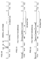
- the prescribed format is the so-called LAPD XID frame format denoting fault indication messages for either a fault condition or a clear condition, as shown in FIG. 11 and FIG. 12, respectively. As shown in both FIG. 11 and FIG.
- the affected virtual circuit ID is included in the DLCI fields, an indication (in this example, 10101111) that the LAPD frame is an XID frame is included in the XID field, an indication that this XID frame is a fault indication message, in accordance with an aspect of the invention, is included in the FI field and an indication, in accordance with another aspect of the invention, of whether the fault indication message denotes a fault or a clear condition is included in the GI field.
- the indication 11111010 in the GI field denotes a fault condition
- the indication 11110000 in the GI field denotes a clear condition.
- fault recovery unit 207 either sends an access circuit remap control signal to access circuit mapping unit 205 causing it to switch a corresponding access circuit to an alternate virtual link, in accordance with an aspect of the invention, or it sends a frame relay remap control signal via circuit path 222 and an alternate virtual link ID via circuit path 223 to frame mapping unit 214 causing it to switch the corresponding virtual link to an alternate virtual link, in accordance with an aspect of the invention, or it sends a corresponding receive fault indication message via circuit path 221 to frame mapping unit 214.
- fault recovery unit 207 monitors for facility or equipment failures, and either orders access circuit mapping unit 205 via access circuit remap control signal or frame mapping unit 214 via frame relay remap control signals to switch the affected access circuits or virtual links to alternate virtual links and/or generates transmit fault indication messages to be passed via transmit frame bus 209 and appropriate ones digital line interface (DLI) units 215-1 through 215-Y and transmit network facilities 212-1 through 212-Y, respectively, to other ones of nodes 101 in network 100 (FIG.1). Further details regarding operation of fault recovery unit 207 are discussed below in conjunction with FIGs. 3 through 6.
- DLI digital line interface
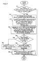
- FIG. 3 depicts, in simplified block diagram form, details of fault recovery unit 207 of FIG. 2. Accordingly, shown are fault indication message receiver 301 and fault indication message generator 302. Fault indication message receiver 301 obtains received fault indication messages via circuit path 218 from receive frame bus 206. If the received fault indication message is for an access circuit in this node, the access circuit remap control signal for that access circuit is activated and supplied via circuit path 220 to access circuit mapping unit 205. If the received fault indication message is on a virtual link that has one or more alternate virtual links in this node, the frame relay remap control signal and the alternate virtual link ID (DLCI) are supplied via circuit paths 222 and 223, respectively, to frame mapping unit 214.
- DLCI alternate virtual link ID
- fault indication message generator 302 is responsive to either a facility failure signal or an equipment failure signal becoming active or inactive. When either failure signal becomes active, fault indication message generator 302 determines if the failure affects an access circuit terminated in this node or if it affects a virtual link that has one or more alternate virtual links in this node. If an access circuit terminated in this node is affected, an access circuit remap control signal for the access circuit is activated.
- a frame relay remap control signal for the virtual link is activated. If the affected virtual circuit is not terminated in this node and if no alternate virtual links exist for the affected virtual link, in this example, two fault indication messages including a fault indication (FIG. 11) are generated for the affected virtual circuit. One fault indication message is sent on the virtual circuit in the direction of the fault and the other one is sent in the direction away from the fault. Similarly, when the fault is cleared, either the access circuit remap control signal or the frame relay remap control signal is deactivated, or two fault indication messages including a clear indication (FIG. 12) are generated. Operation of fault indication message generator 302 is described below in conjunction with the flow chart shown in FIGs. 5, 6 and 7.
- FIG. 4 is a flow chart showing a sequence of operations effected in fault indication message receiver 301 of FIG. 3. Accordingly, the sequence is entered via step 401. Thereafter, conditional branch point 402 tests to determine if there is a received fault indication message on receive frame bus 206 (FIG. 2). If the test result is NO, the sequence is exited via step 403. If the test result in step 402 is YES, operational block 404 determines the virtual link identification corresponding to the obtained fault indication message. In the LAPD format this identification (ID) is known as the DLCI. Then, conditional branch point 405 tests to determine if the determined virtual link ID (DLCI) is mapped to an access circuit in this node.
- ID the virtual link identification
- conditional branch point 406 tests to determine if the determined virtual link ID (DLCI) has one or more alternate virtual links in this node. If the test result in step 406 is YES, conditional branch point 407 tests to determine if the fault indication message indicates a fault. As indicated above, a fault indication message indicates a fault, in this example, when field GI includes 1111010, as shown in FIG. 11. If the test result in step 407 is YES, operational block 408 selects one of the alternate virtual link IDs and supplies it as an output from fault recovery unit 207 via circuit path 223 to frame mapping unit 214. This selection may be done in many ways, including measuring congestion in the network facilities and choosing an alternate virtual link on the least congested network facility.
- Operational block 409 then supplies as an output an activated frame relay remap control signal for this virtual link via circuit path 222 to the frame mapping unit 214.
- the sequence is then exited via step 403.
- the fault indication message indicates a clear condition and operational block 410 supplies as an output a deactivated frame relay remap control signal via circuit path 222 to frame mapping unit 214.
- a fault indication indicates a clear condition, in this example, when field GI includes 11110000, as shown in FIG. 11.
- the sequence is then exited via step 403. If the test result of 406 is NO, the virtual link denoted by this DLCI is frame relayed via frame mapping unit 214 (FIG. 2) through this node.
- operational block 411 supplies as an output the received fault indication message to frame mapping unit 214 (FIG. 2). Thereafter, the sequence is exited via step 403. If the test result in step 405 is YES, the virtual link denoted by this DLCI is mapped to an appropriate access circuit in this node, i.e., the virtual circuit is terminated at this node.
- Conditional branch point 412 tests to determine whether the received fault indication message indicates the activating of a fault or the clearing of a fault (FIG. 11 or FIG. 12, respectively).
- test block 412 If the test result in step 412 is YES, indicating the activation of a fault, operational block 413 supplies as an output an activated access circuit remap control signal for this virtual link ID (DLCI) to access circuit mapping unit 205 (FIG. 2). Thereafter, the sequence is exited via step 403. If the test result in step 412 is NO, indicating clearing of a fault, operational block 409 supplies as an output a deactivated access circuit remap control signal for this virtual link ID (DLCI) to access circuit mapping unit 205 (FIG. 2). Thereafter, the sequence is exited via step 403.
- DLCI virtual link ID
- steps 402,404 and 405 could be reversed in order, such that steps 404 and 405 are performed for all received frames and if the test result in step 405 is YES, then step 402 is performed to determine if the received frame includes a fault indication message.
- conditional branch point 505 If the test result in step 504 is NO, control is supplied to conditional branch point 505 (FIG. 6). If the test result in step 504 is YES, operational block 506 determines which access circuits are affected. It is noted that more than one access circuit may be affected. Then, operational block 507 determines the virtual link ID (DLCI) for each affected access circuit. Conditional branch point 508 tests to determine if the change in state of either failure signal is from inactive to active. If the test result in step 508 is YES, operational block 509 activates the access circuit remap control signal for this virtual link ID (DLCI). Then, control is supplied to conditional branch point 505 (FIG.
- DLCI virtual link ID
- test block 510 deactivates the access circuit remap control signal for this virtual link ID (DLCI). Thereafter, control is supplied to conditional branch point 505 (FIG. 6).
- Conditional branch point 505 tests to determine if the change in state of either failure signal in step 502 affects any virtual links for which one or more alternate virtual links are present in this node. If the test result in step 505 is NO, control is supplied to conditional branch point 511 (FIG. 7). If the test result in step 505 is YES, operational block 512 determines the virtual link IDs (DLCIs) of the virtual links that have alternate virtual links present in this node.
- DLCIs virtual link IDs
- conditional branch point 513 tests to determine if the change in state in step 502 was from inactive to active, indicating a fault has occurred. If the test result in step 513 is YES, indicating a fault, operational block 514 selects an alternate virtual link for each determined virtual link ID (DLCI) from step 512 and supplies the 5 alternate virtual link ID to frame mapping unit 214. This selection may be done by considering network facility congestion, by using a priority scheme or in some other manner. Operational block 515 then activates the frame relay remap control signal for the determined virtual link IDs and supplies it as an output to frame mapping unit 214. Control is then passed to conditional branch point 511 (FIG.7).
- DLCI determined virtual link ID
- step 516 supplies as an output a deactivated frame relay remap control signal to frame mapping unit 214 for the virtual link IDs determined in step 512.
- Control is then passed to conditional branch point 511 (FIG. 7).
- Conditional branch point 511 tests to determine if the change in state of either failure signal in step 502 affects any so-called frame relay connection, i.e., virtual link to virtual link connection for which no alternate virtual links are present in this node. It is noted that an affected frame relay connection includes a faulted or cleared virtual link and a connected virtual link. If the test result in step 511 is NO, the sequence is exited via step 503 (FIG. 5).
- operational block 517 determines which frame relay connections are affected by the fault.
- Operational block 518 determines the virtual link ID (DLCI) and the network facility of the connected virtual link for each affected virtual link.
- Operational block 519 generates, in this example, two fault indication messages for each affected frame relay connection.
- the virtual link ID (DLCI) that was determined in step 518 is used as the address for one of the fault indication messages and the affected virtual link ID is used for the address of the other fault indication message.
- Conditional branch point 520 tests to determine whether the change in state of either failure signal in step 502 is from inactive to active.
- operational block 521 causes the fault indication messages generated in block 519 to indicate "fault” (GI field includes 1111010, FIG. 11). If the test result in step 520 is NO, operational block 522 causes the fault indication messages generated in block 519 to indicate "clear” (GI field includes 11110000, FIG. 12). Thereafter, operational block 523 supplies as an output the fault indication messages to transmit frame bus 209 (FIG. 2). Then, the sequence is exited via step 503 (FIG. 5).
- FIG. 8 is a flow chart of a sequence of operations effected by access circuit mapping unit 205 of FIG. 2. Accordingly, the sequence is entered via step 801. Thereafter, conditional branch point 802 tests to determine if a received frame is present on receive frame bus 206 (FIG. 2). If the test result in step 802 is YES, operational block 803 determines the virtual link ID (DLCI) for the received frame. Conditional Branch point 804 tests to determine if the access circuit remap control signal is active for this virtual link ID (DLCI). If the test result in 804 is YES, operational block 805 causes the virtual link ID (DLCI) determined in step 803 to be modified to a DLCI for the appropriate virtual link ID of the primary virtual circuit.
- DLCI virtual link ID
- test result in step 804 is NO, no action is taken to change the virtual link ID (DLCI) and operational block 806 supplies the received frame to depacketizer 208 (FIG. 2). Thereafter, the sequence is exited via step 807.
- conditional branch point 808 tests to determine if there is a generated frame from packetizer 204 (FIG. 2). If the test result in step 808 is NO, the sequence is exited via step 807. If the test result in step 808 is YES, operational block 809 determines the virtual link ID (DLCI) for the generated frame. Then, conditional branch point 810 tests to determine if the access circuit remap control signal is active for this virtual link ID (DLCI).
- step 810 If the test result in step 810 is YES, operational block 811 changes the virtual link ID (DLCI) in the generated frame to the alternate virtual link ID (DLCI) for the appropriate alternate virtual link. Then, operational block 812 supplies as an output the generated frame to transmit frame bus 209 (FIG. 2). Thereafter, the sequence is exited via step 807.
- step 810 if the test result is NO, the generated frame DLCI is not changed and steps 812 and 807 are iterated.
- FIG. 9 is a flow chart of a sequence of operations effected in frame mapping unit 214 of FIG. 2. This flow chart does not completely describe the LAPD frame relay function known to the art but only those functions necessary to this embodiment of the invention. Accordingly, the sequence is entered via step 901. Then, conditional branch point 902 tests to determine if there is a received frame on receive frame bus 206 (FIG. 2). If the test result in step 902 is NO, conditional branch point 903 tests to determine if there is a receive fault indication message on receive frame bus 206 (FIG. 2). If the result in step 903 is NO, the sequence is exited via step 904.
- operational block 905 determines the virtual link ID (DLCI) for the received frame.
- Operational block 906 determines the virtual link ID (DLCI) for the connected virtual link, i.e., the frame relay connection.
- Conditional branch point 907 tests to determine if the frame relay remap control signal from fault recovery unit 207 is active for the virtual link ID (DLCI) determined in block 906. If the test result in step 907 is YES, operational block 908 determines the alternate virtual link ID (DLCI) as supplied from fault recovery unit 207 (FIG. 2). Operational block 909 then changes the virtual link ID (DLCI) of the received frame to the alternate virtual link ID (DLCI) determined in step 908.
- control is then passed to operational block 911. If the test result in step 907 is NO, operational block 910 changes the virtual link ID (DLCI) of the received frame to the virtual link ID (DLCI) for the connected virtual link. Operational block 911 supplies as an output the modified "received" frame to the transmit frame bus 209 (FIG. 2). Thereafter, the sequence is exited by step 904.
- DLCI virtual link ID
- DLCI virtual link ID
- fault indications i.e., fault or clear
- fault indication messages including the identification of all virtual circuits being transported on a network facility could be employed. See co-pending application EP-A-0 452 466 (F.D. Fite Case 2) for an arrangement using such fault indication messages.
- still other transport techniques may be employed to transport the fault indication message to the unknown nodes to effect the fault recovery in accordance with the principles of the invention.
Landscapes
- Engineering & Computer Science (AREA)
- Computer Networks & Wireless Communication (AREA)
- Signal Processing (AREA)
- Computer Security & Cryptography (AREA)
- Data Exchanges In Wide-Area Networks (AREA)
Claims (14)
- Vorrichtung zur Verwendung in einem Netzwerkknoten (z.B. 101-1) zur Wiedererlangung der Betriebsfähigkeit nach Fehlern auf Übertragungswegen (211-1, 211-Y) einschließlich wenigstens eines virtuellen Stromkreises, wobei der Netzwerkknoten zur Verwendung in einem Netzwerk mit einer Vielzahl solcher Knoten bestimmt ist, mit einer Vorrichtung (DLls 213-1, 213-Y) zur Feststellung von Fehlern auf wenigstens einem, an den Netzwerkknoten angeschlossenen Übertragungsweg wobei
jeder virtuelle Stromkreis eine erste Zugriffsschaltung an einem Ursprungsnetzwerkknoten, eine zweite Zugriffsschaltung an einem Bestimmungsnetzwerkknoten und wenigstens eine virtuelle Linkleitung umfaßt,
dadurch gekennzeichnet, daß
der Netzwerkknoten keine Information bezüglich der Netzwerktopologie außer für Netzwerkeinrichtungen besitzt, die an den Netzwerkknoten angeschlossen sind,
daß ein Fehleranzeigenachrichtengenerator (302) vorgesehen ist, der Fehleranzeigenachrichten (über 519) für virtuelle, durch den angezeigten Fehler beeintrachtigte Schaltungen erzeugt, die nicht an den Netzwerkknoten angeschlossen sind und keinen alternativen, virtuellen Stromkreis in dem Netzwerkknoten besitzt, einschließlich einer Detektoreinrichtung (302 über 502, 504, 506, 507) zur Feststellung, ob ein virtueller, durch einen festgestellten Fehler beeinträchtigter Stromkreis an den Netzwerkknoten angeschlossen ist, und zur Feststellung (302 über 502, 504, 505, 512) ob ein durch den Fehler beeinträchtigter, virtueller Stromkreis wenigstens einen alternativen virtuellen Stromkreis in dem Netzwerkknoten besitzt,
daß eine Übertragungseinrichtung (302 über 523, 209) vorgesehen ist, die jede erzeugte Fehleranzeigennachricht auf zugeordneten virtuellen Stromkreisen zu einem anderen Netzwerkknoten im Netzwerk überträgt, und
daß eine Vermittlungsvorrichtung (205, 209, 214) vorgesehen ist, die jeden beeinträchtigten virtuellen Stromkreis, für den bestimmt worden ist, daß er an den Netzwerkknoten angeschlossen ist oder wenigstens eine alternative, virtuelle Linkleitung in dem Netzwerkknoten besitzt, auf zugeordnete alternative, virtuelle Stromkreise zur Übertragung zu einem Bestimmungsnetzwerkknoten umzuschaltet. - Vorrichtung nach Anspruch 1 mit ferner einem Empfänger (301) zum Empfangen von Fehleranzeigenachrichten einschließlich einer Detektorvorrichtung (301 über 402, 404, 405) zur Feststellung, ob ein in einer empfangenen Fehleranzeigenachricht identifizierter, virtueller Stromkreis an das Netzwerk angeschlossen ist, und zur Feststellung (301 über 402, 404-406), ob ein in einer empfangenen Fehleranzeigenachricht identifizierter, virtueller Stromkreis wenigstens eine alternative, virtuelle Linkleitung in dem Netzwerkknoten besitzt und ferner mit einer Übertragungseinrichtung (301 über 411, 214) zur Übertragung jeder empfangenen Fehleranzeigenachricht, die nicht einem virtuellen, an den Netzwerkknoten angeschlossenen Stromkreis zugeordnet ist oder nicht wenigstens einen alternativen, virtuellen Stromkreis im Netzwerkknoten besitzt, auf zugeordneten virtuellen Stromkreisen zu einem anderen Netzwerkknoten im Netzwerk.
- Vorrichtung nach Anspruch 2, bei der die Übertragungsvorrichtung (302 über 523, 209) in dem Fehleranzeigenachrichtengenerator (302) eine Übertragungsvorrichtung (209) enthält, die Fehleranzeigenachrichten in Richtung weg von dem festgestellten Fehler und in Richtung zu dem festgestellten Fehler auf den zugeordneten virtuellen Stromkreisen überträgt.
- Vorrichtung nach Anspruch 2, bei der die empfangene Fehleranzeigenachricht die Identität einer beeinträchtigten virtuellen Linkleitung eines virtuellen
Stromkreises enthält und die Detektorvorrichtung in dem Empfänger (301) einen Steuersignalgenerator (301 über 402, 404, 405, 412-414) enthält, der ein erstes Steuersignal erzeugt, das darstellt, ob die virtuelle, in der empfangenen Fehleranzeigenachricht identifizierte Linkleitung einer Zugriffsschaltung im Netzwerkknoten zugeordnet ist, und ein zweites Steuersignal erzeugt (301 über 402, 404-410), das darstellt, daß wenigstens eine alternative virtuelle Linkleitung im Netzwerkknoten für die virtuelle, in der empfangenen Fehleranzeigenachricht identifizierte Linkleitung vorhanden ist, bei der die Vermittlungsvorrichtung (205, 209, 214) unter Ansprechen auf das erste Steuersignal die Identität (205 über 810, 811) der identifizierten, virtuellen Linkleitung in die Identität einer alternativen virtuellen Linkleitung ändert, wenn das erste Steuersignal anzeigt, daß die virtuelle Linkleitung einer Zugriffsschaltung im Netzwerkknoten zugeordnet ist, wobei die Zugriffsschaltung einem alternativen, virtuellen Stromkreis zur Übertragung (205 über 812, 209) zu der Zugriffsschaltung in dem Bestimmungsnetzwerkknoten zugeordnet ist, und die Vermittlungsvorrichtung (214, 209) unter Ansprechen auf das zweite Steuersignal die wenigstens eine alternative, virtuelle Linkleitung auswählt und identifiziert (214 über 902-909), so daß die identifizierte beeinträchtigte virtuelle Linkleitung der gewählten, wenigstens einen, alternativen, virtuellen Linkleitung zur Übertragung (214 über 911, 209) zu der Zugriffsschaltung im Bestimmungsnetzwerkknoten zugeordnet ist. - Vorrichtung nach Anspruch 2, bei der die 0Detektorvorrichtung im Fehleranzeigenachrichtengenerator (302) eine Identifiziervorrichtung (302 über 502, 504, 506) aufweist, die durch den festgestellten Fehler beeinträchtigte Zugriffsschaltungen im Netzwerkknoten identifiziert, ferner eine Vorrichtung (302 über 507) zur Identifizierung einer zugeordneten virtuellen Linkleitung für jeden durch den festgestellten Fehler beeinträchtigte Zugriffsschaltung im Netzwerkknoten und eine Vorrichtung (302 über 509) zur Erzeugung eines Zugriffsschaltungs-Steuersignals, das angibt, daß eine entsprechende Zugriffsschaltung einer virtuellen, durch den festgestellten Fehler beeinträchtigten Linkleitung zugeordnet ist, und eine Vorrichtung (302 über 505, 512-514) zur Auswahl und Identifizierung wenigstens einer alternativen, virtuellen Linkleitung im Netzwerkknoten für jede virtuelle Linkleitung, die dem durch den Fehler beeinträchtigten Netzwerkknoten zugeordnet und nicht an den Netzwerkknoten angeschlossen ist, sowie eine Vorrichtung (302 über 515) zur Erzeugung eines Rahmenrelais-Steuersignals, das angibt, daß eine identifizierte, alternative, virtuelle Linkleitung der identifizierten, beeinträchtigten, virtuellen Linkleitung zuzuordnen ist, wobei die Vermittlungsvorrichtung (205, 209, 214) eine Vorrichtung (205 über 810, 811) enthält, die unter Ansprechen auf das Zugriffsschaltungssteuersignal die Identität der virtuellen, der identifizierten Zugriffsschaltung zugeordneten Linkleitung in die Identität einer alternativen, virtuellen Linkleitung ändert, wobei die Zugriffsschaltung einem alternativen, virtuellen Stromkreis zugeordnet wird, und eine Vorrichtung (214 über 907-909), die unter Ansprechen auf das Rahmenrelais-Steuersignal die identifizierte, beeinträchtigte, virtuelle Linkleitung der identifizierten, alternativen, virtuellen Linkleitung zuordnet.
- Vorrichtung nach Anspruch 2, bei der der virtuelle Stromkreis eine virtuelle Linkleitung enthalten kann, die einer anderen virtuellen Linkleitung in einem Netzwerkknoten zugeordnet ist, der Fehleranzeigenachrichtengenerator (302) eine Identifiziervorrichtung (302 über 502, 505, 511, 517, 518) enthält, die eine virtuelle Linkleitung identifiziert, der eine virtuelle, durch den festgestellten Fehler beeinträchtigte Linkleitung zugeordnet ist, und eine Vorrichtung (302 über 519), die die Identität der identifizierten, virtuellen Linkleitung als Adresse für die Fehleranzeigenachricht umfaßt, die für den beeinträchtigten, virtuellen Stromkreis erzeugt wird, wobei die Übertragungsvorrichtung (302 über 523, 209) die erzeugte Fehleranzeigenachricht als Ausgangssignal auf einen zugeordneten, beeinträchtigten, virtuellen Stromkreis gibt.
- Vorrichtung nach Anspruch 2, bei der die Übertragungsvorrichtung im Empfänger (301) eine Vorrichtung (301 über 402, 404) zur Identifizierung einer virtuellen Linkleitung in der empfangenen Fehleranzeigenachricht enthält, ferner eine Vorrichtung (301 über 402, 404-406) zur Identifizierung einer zugeordneten, virtuellen Linkleitung, mit der die identifizierte, virtuelle Linkleitung zu verbinden ist, und eine Vorrichtung (301 über 408, 214 über 909) zur Änderung der Identifizierung der virtuellen Linkleitung in der Fehleranzeigenachricht, auf die der zugeordneten, virtuellen Linkleitung, und eine Vorrichtung (214 über 911, 209), die die Fehleranzeigenachricht einschließlich der Identität der zugeordneten, virtuellen Linkleitung als Ausgangssignal auf einen zugeordneten, beeinträchtigten, virtuellen Stromkreis gibt.
- Vorrichtung nach Anspruch 2, bei der die Fehleranzeigenachricht einen Rahmen mit einer Vielzahl von Feldern, einem vorbestimmten Feld einschließlich der Identität einer virtuellen Linkleitung auf einem virtuellen Stromkreis umfaßt, der durch den Fehler beeinträchtigt ist, und ein Feld umfaßt, das eine Anzeige enthält, ob ein Fehlerzustand besteht.
- Vorrichtung nach Anspruch 8, bei der ein Feld im Rahmen eine Anzeige enthält, die darstellt, daß der Rahmen eine Fehleranzeigenachricht ist.
- Vorrichtung nach Anspruch 9, bei der Rahmen ein LAPD XID-Rahmen mit einem Feld ist, das eine Anzeige enthält, daß der Rahmen ein XID-Rahmen ist.
- Verfahren zur Anwendung in einem Netzwerkknoten (z.B. 101-1) für eine Wiedergewinnung der Betriebsfähigkeit nach Fehlern auf Übertragungswegen (211-1, 211-Y) einschließlich wenigstens eines, an einen Netzwerkknoten angeschlossenen, virtuellen Stromkreises, wobei der Netzwerkknoten zur Verwendung in einem Netzwerk mit einer Vielzahl solcher Knoten vorgesehen ist, mit dem Schritt Feststellen von Fehlern auf wenigstens einem, dem Netzwerkknoten zugeordneten Übertragungsweg, wobei jeder virtuelle Stromkreis eine erste Zugriffsschaltung an einem Ursprungsnetzwerkknoten, eine zweite Zugriffsschaltung an einem Bestimmungsnetzwerkknoten und wenigstens eine virtuelle Linkleitung umfaßt,
dadurch gekennzeichnet, daß
der Netzwerkknoten keine Informationen bezüglich der Netzwerktopologie außer für Netzwerkeinrichtungen besitzt, die an den Netzwerkknoten angeschlossen ist,
das festgestellt wird (302 über 502, 504, 506, 507), ob ein virtueller, durch einen festgestellten Fehler beeinträchtigter Stromkreis an den Netzwerkknoten angeschlossen ist, daß festgestellt wird (302 über 502, 504, 505 512), ob ein, durch den Fehler beeinträchtigter, virtueller Stromkreis wenigstens einen alternativen, virtuellen Stromkreis in dem Netzwerkknoten besitzt,
Erzeugen von Fehleranzeigenachrichten (302 über 519) für virtuelle, durch den festgestellten Fehler beeinträchtigte Stromkreise, die nicht an den Netzwerkknoten angeschlossen sind und keinen alternativen, virtuellen Stromkreis in dem Netzwerkknoten besitzen,
daß jede erzeigte Fehleranzeigenachricht auf zugeordneten, virtuellen Stromkreisen zu anderen Netzwerkknoten im Netzwerk übertragen wird (302 über 523, 209), und
daß jeder beeinträchtigte, virtuelle Stromkreis, für den festgestellt worden ist, daß er an den Netzwerkknoten angeschlossen ist oder wenigstens eine alternative, virtuelle Linkleitung in dem Netzwerkknoten besitzt, auf zugeordnete, alternative, virtuelle Stromkreise zur Übertragung zu einem Bestimmungsnetzwerkknoten umgeschaltet wird (über 205, 209, 214). - Verfahren nach Anspruch 11 mit ferner den Schritten:
Empfangen von Fehleranzeigenachrichten (über 301) einschließlich der Feststellung (301 über 402, 404, 405), ob ein in einer empfangenen Fehleranzeigenachricht identifizierter, virtueller Stromkreis an den Netzwerkknoten angeschlossen ist und Feststellen (301 über 401, 404-406), ob ein in einer empfangenen Fehleranzeigenachricht identifizierter, virtueller Stromkreis wenigstens eine alternative, virtuelle Linkleitung im Netzwerkknoten besitzt, und
Übertragen (301 über 411, 214) jeder empfangenen Fehleranzeigenachricht, die nicht einem virtuellen, an den Netzwerkknoten angeschlossenen Stromkreis zugeordnet ist oder nicht wenigstens einen alternativen, virtuellen Stromkreis im Netzwerk besitzt, auf zugeordneten, virtuellen Stromkreisen zu einen anderen Netzwerkknoten im Netzwerk. - Verfahren nach Anspruch 12, bei dem ein Feld in dem Rahmen eine Anzeige enthält, die darstellt, daß der Rahmen eine Fehleranzeigenachricht ist.
- Verfahren nach Anspruch 13, bei dem der Rahmen ein LAPD XID-Rahmen mit einem Feld ist, das eine Anzeige enthält, daß der Rahmen ein XID-Rahmen ist.
Applications Claiming Priority (3)
| Application Number | Priority Date | Filing Date | Title |
|---|---|---|---|
| US431795 | 1989-11-06 | ||
| US07/431,795 US4999829A (en) | 1989-11-06 | 1989-11-06 | Automatic fault recovery in a packet network |
| PCT/US1990/006549 WO1991007032A1 (en) | 1989-11-06 | 1990-11-02 | Automatic fault recovery in a packet network |
Publications (2)
| Publication Number | Publication Date |
|---|---|
| EP0452487A1 EP0452487A1 (de) | 1991-10-23 |
| EP0452487B1 true EP0452487B1 (de) | 1995-08-23 |
Family
ID=23713450
Family Applications (1)
| Application Number | Title | Priority Date | Filing Date |
|---|---|---|---|
| EP91901187A Expired - Lifetime EP0452487B1 (de) | 1989-11-06 | 1990-11-02 | Automatische fehlerberichtigung in einem paketnetzwerk |
Country Status (8)
| Country | Link |
|---|---|
| US (1) | US4999829A (de) |
| EP (1) | EP0452487B1 (de) |
| JP (1) | JPH04504347A (de) |
| AU (1) | AU626746B2 (de) |
| CA (1) | CA2042390C (de) |
| DE (1) | DE69021865T2 (de) |
| IL (1) | IL96257A0 (de) |
| WO (1) | WO1991007032A1 (de) |
Families Citing this family (44)
| Publication number | Priority date | Publication date | Assignee | Title |
|---|---|---|---|---|
| US4993015A (en) * | 1989-11-06 | 1991-02-12 | At&T Bell Laboratories | Automatic fault recovery in a packet network |
| US5016243A (en) * | 1989-11-06 | 1991-05-14 | At&T Bell Laboratories | Automatic fault recovery in a packet network |
| CA2044718C (en) * | 1990-06-18 | 1998-07-28 | Katsumi Omuro | Rerouting and change-back systems for asynchronous transfer mode network |
| US6847611B1 (en) * | 1990-12-10 | 2005-01-25 | At&T Corp. | Traffic management for frame relay switched data service |
| US5182744A (en) * | 1991-01-03 | 1993-01-26 | At&T Bell Laboratories | Telecommunications network restoration architecture |
| US5278977A (en) * | 1991-03-19 | 1994-01-11 | Bull Hn Information Systems Inc. | Intelligent node resident failure test and response in a multi-node system |
| JPH04351032A (ja) * | 1991-05-28 | 1992-12-04 | Fujitsu Ltd | ネットワーク切替制御方法 |
| US6771617B1 (en) * | 1993-06-17 | 2004-08-03 | Gilat Satellite Networks, Ltd. | Frame relay protocol-based multiplex switching scheme for satellite mesh network |
| US5434850A (en) | 1993-06-17 | 1995-07-18 | Skydata Corporation | Frame relay protocol-based multiplex switching scheme for satellite |
| US5442624A (en) * | 1993-10-29 | 1995-08-15 | At&T Corp. | Dynamic access control for an ATM network |
| GB9400057D0 (en) * | 1994-01-05 | 1994-03-02 | Plessey Telecomm | Telecommunications system |
| US5640504A (en) * | 1994-01-24 | 1997-06-17 | Advanced Computer Applications, Inc. | Distributed computing network |
| US5495471A (en) * | 1994-03-09 | 1996-02-27 | Mci Communications Corporation | System and method for restoring a telecommunications network based on a two prong approach |
| US5459716A (en) * | 1994-04-15 | 1995-10-17 | Mci Communications Corporation | Facility restoration for telecommunications networks |
| US5452294A (en) * | 1994-07-05 | 1995-09-19 | Motorola, Inc. | Method and apparatus for adaptive route selection in communication networks |
| EP0699006A1 (de) * | 1994-08-23 | 1996-02-28 | BELL TELEPHONE MANUFACTURING COMPANY Naamloze Vennootschap | Verfahren zur Umleitung eines Datenstroms |
| EP0699008A1 (de) * | 1994-08-23 | 1996-02-28 | BELL TELEPHONE MANUFACTURING COMPANY Naamloze Vennootschap | Verfahren zur Umleitung eines Datenstroms |
| US5659544A (en) * | 1994-10-17 | 1997-08-19 | Lucent Technologies Inc. | Method and system for distributed control in wireless cellular and personal communication systems |
| US5581543A (en) * | 1995-02-27 | 1996-12-03 | Motorola, Inc. | Communication network and method which respond to a failed link |
| US5646936A (en) * | 1995-06-22 | 1997-07-08 | Mci Corporation | Knowledge based path set up and spare capacity assignment for distributed network restoration |
| US5748612A (en) * | 1995-08-10 | 1998-05-05 | Mcdata Corporation | Method and apparatus for implementing virtual circuits in a fibre channel system |
| US5878428A (en) * | 1995-11-20 | 1999-03-02 | International Business Machines Corporation | System, method, and article of manufacture for adding transactional recovery to a binary class in an object oriented system |
| US5768300A (en) * | 1996-02-22 | 1998-06-16 | Fujitsu Limited | Interconnect fault detection and localization method and apparatus |
| US5991296A (en) * | 1996-02-22 | 1999-11-23 | Fujitsu, Ltd. | Crossbar switch and method with reduced voltage swing and no internal blocking data path |
| US5805569A (en) * | 1996-04-30 | 1998-09-08 | Telefonaktiebolaget Lm Ericsson | Packet data communications system having a malfunction list |
| US6456596B2 (en) | 1996-07-23 | 2002-09-24 | Marconi Communications Limited | Synchronous transmission systems |
| US5922077A (en) * | 1996-11-14 | 1999-07-13 | Data General Corporation | Fail-over switching system |
| US5838660A (en) * | 1996-11-14 | 1998-11-17 | Mci Communications Corporation | Dynamic restoration process |
| US6031817A (en) * | 1996-12-23 | 2000-02-29 | Cascade Communications Corporation | System and method for providing notification of malfunctions in a digital data network |
| US6081524A (en) * | 1997-07-03 | 2000-06-27 | At&T Corp. | Frame relay switched data service |
| US6311288B1 (en) * | 1998-03-13 | 2001-10-30 | Paradyne Corporation | System and method for virtual circuit backup in a communication network |
| US6498779B1 (en) * | 1998-05-22 | 2002-12-24 | Alcatel Canada Inc. | Multiple endpoint paths |
| US6651189B1 (en) * | 1998-09-02 | 2003-11-18 | Korea Telecommunication Authority | Communication network disturbance management method using top-down method |
| US6496941B1 (en) * | 1998-12-29 | 2002-12-17 | At&T Corp. | Network disaster recovery and analysis tool |
| JP3747740B2 (ja) * | 2000-05-22 | 2006-02-22 | 株式会社日立製作所 | インタネットゲートウェイシステムでの迂回制御方法 |
| JP4095258B2 (ja) * | 2001-04-03 | 2008-06-04 | 株式会社エヌ・ティ・ティ・ドコモ | 移動通信システム、関門交換機選択サーバ及び関門交換機選択方法 |
| US6987735B2 (en) | 2001-05-24 | 2006-01-17 | International Business Machines Corporation | System and method for enhancing the availability of routing systems through equal cost multipath |
| US6882627B2 (en) * | 2001-06-14 | 2005-04-19 | Tropic Networks | Methods and apparatus for selecting multiple paths taking into account shared risk |
| US7126907B2 (en) * | 2001-08-31 | 2006-10-24 | Tropic Networks Inc. | Label switched communication network, a method of conditioning the network and a method of data transmission |
| US8275864B1 (en) * | 2002-12-20 | 2012-09-25 | Symantec Operating Corporation | Peer-to-peer network with recovery capability |
| US7688739B2 (en) * | 2005-08-02 | 2010-03-30 | Trilliant Networks, Inc. | Method and apparatus for maximizing data transmission capacity of a mesh network |
| CN100454849C (zh) * | 2005-08-05 | 2009-01-21 | 华为技术有限公司 | 下一代网络中的故障检测方法 |
| US8300798B1 (en) | 2006-04-03 | 2012-10-30 | Wai Wu | Intelligent communication routing system and method |
| US7876751B2 (en) | 2008-02-21 | 2011-01-25 | International Business Machines Corporation | Reliable link layer packet retry |
Family Cites Families (8)
| Publication number | Priority date | Publication date | Assignee | Title |
|---|---|---|---|---|
| US4777595A (en) * | 1982-05-07 | 1988-10-11 | Digital Equipment Corporation | Apparatus for transferring blocks of information from one node to a second node in a computer network |
| US4593154A (en) * | 1983-07-08 | 1986-06-03 | Nissan Motor Company, Limited | Loop-type data transmission/reception network |
| US4550397A (en) * | 1983-12-16 | 1985-10-29 | At&T Bell Laboratories | Alternate paths in a self-routing packet switching network |
| US4679186A (en) * | 1984-09-26 | 1987-07-07 | American Telephone And Telegraph Company, At&T Bell Laboratories | Alternate self-routing packet switching node having fault detection capabilities |
| US4679189A (en) * | 1985-11-27 | 1987-07-07 | American Telephone And Telegraph Company | Alternate routing arrangement |
| US4703477A (en) * | 1986-02-28 | 1987-10-27 | American Telephone And Telegraph Company At&T Bell Laboratories | Packet information field data format |
| JPH0831869B2 (ja) * | 1987-02-23 | 1996-03-27 | 株式会社日立製作所 | データ伝送方法及びデータ伝送装置 |
| US4920529A (en) * | 1987-02-27 | 1990-04-24 | Hitachi, Ltd. | Network control method and apparatus therefor |
-
1989
- 1989-11-06 US US07/431,795 patent/US4999829A/en not_active Expired - Lifetime
-
1990
- 1990-11-02 EP EP91901187A patent/EP0452487B1/de not_active Expired - Lifetime
- 1990-11-02 DE DE69021865T patent/DE69021865T2/de not_active Expired - Fee Related
- 1990-11-02 WO PCT/US1990/006549 patent/WO1991007032A1/en not_active Ceased
- 1990-11-02 JP JP3501464A patent/JPH04504347A/ja active Pending
- 1990-11-02 CA CA002042390A patent/CA2042390C/en not_active Expired - Fee Related
- 1990-11-02 AU AU69060/91A patent/AU626746B2/en not_active Ceased
- 1990-11-06 IL IL96257A patent/IL96257A0/xx not_active IP Right Cessation
Also Published As
| Publication number | Publication date |
|---|---|
| WO1991007032A1 (en) | 1991-05-16 |
| DE69021865D1 (de) | 1995-09-28 |
| EP0452487A1 (de) | 1991-10-23 |
| IL96257A0 (en) | 1991-08-16 |
| US4999829A (en) | 1991-03-12 |
| DE69021865T2 (de) | 1996-05-02 |
| CA2042390C (en) | 1994-08-30 |
| CA2042390A1 (en) | 1991-05-07 |
| AU626746B2 (en) | 1992-08-06 |
| JPH04504347A (ja) | 1992-07-30 |
| AU6906091A (en) | 1991-05-31 |
Similar Documents
| Publication | Publication Date | Title |
|---|---|---|
| EP0452487B1 (de) | Automatische fehlerberichtigung in einem paketnetzwerk | |
| EP0452466B1 (de) | Automatische fehlererholung in einem paketnetz | |
| US5016243A (en) | Automatic fault recovery in a packet network | |
| US6898630B2 (en) | Network management system utilizing notification between fault manager for packet switching nodes of the higher-order network layer and fault manager for link offering nodes of the lower-order network layer | |
| US7027390B2 (en) | Packet routing apparatus and a method of communicating a packet | |
| EP2074752B1 (de) | Elastizitätsverfahren in verbindungsorientierten kommunikationsnetzen | |
| US7961602B2 (en) | Method and device using a backup communication path to transmit excess traffic | |
| US8917592B2 (en) | Communication apparatus, system, and method | |
| US20030063613A1 (en) | Label switched communication network and system and method for path restoration | |
| CN110708245B (zh) | 多控制器架构下的sdn数据平面故障监测与恢复方法 | |
| GB2471761A (en) | Fault recovery path reconfiguration in ring networks | |
| US20040213148A1 (en) | Network data re-routing | |
| US6662308B1 (en) | Dual-homing select architecture | |
| WO2001067677A2 (en) | Layer 3 routing in self-healing networks | |
| CA2358174A1 (en) | A label switched communication network and system and method for path restoration |
Legal Events
| Date | Code | Title | Description |
|---|---|---|---|
| PUAI | Public reference made under article 153(3) epc to a published international application that has entered the european phase |
Free format text: ORIGINAL CODE: 0009012 |
|
| 17P | Request for examination filed |
Effective date: 19910702 |
|
| AK | Designated contracting states |
Kind code of ref document: A1 Designated state(s): DE FR GB IT |
|
| 17Q | First examination report despatched |
Effective date: 19940314 |
|
| RAP3 | Party data changed (applicant data changed or rights of an application transferred) |
Owner name: AT&T CORP. |
|
| GRAA | (expected) grant |
Free format text: ORIGINAL CODE: 0009210 |
|
| AK | Designated contracting states |
Kind code of ref document: B1 Designated state(s): DE FR GB IT |
|
| PGFP | Annual fee paid to national office [announced via postgrant information from national office to epo] |
Ref country code: GB Payment date: 19950915 Year of fee payment: 6 |
|
| REF | Corresponds to: |
Ref document number: 69021865 Country of ref document: DE Date of ref document: 19950928 |
|
| ET | Fr: translation filed | ||
| PGFP | Annual fee paid to national office [announced via postgrant information from national office to epo] |
Ref country code: DE Payment date: 19951027 Year of fee payment: 6 |
|
| ITF | It: translation for a ep patent filed | ||
| PGFP | Annual fee paid to national office [announced via postgrant information from national office to epo] |
Ref country code: FR Payment date: 19951102 Year of fee payment: 6 |
|
| PLBE | No opposition filed within time limit |
Free format text: ORIGINAL CODE: 0009261 |
|
| STAA | Information on the status of an ep patent application or granted ep patent |
Free format text: STATUS: NO OPPOSITION FILED WITHIN TIME LIMIT |
|
| 26N | No opposition filed | ||
| PG25 | Lapsed in a contracting state [announced via postgrant information from national office to epo] |
Ref country code: GB Effective date: 19961102 |
|
| GBPC | Gb: european patent ceased through non-payment of renewal fee |
Effective date: 19961102 |
|
| PG25 | Lapsed in a contracting state [announced via postgrant information from national office to epo] |
Ref country code: FR Effective date: 19970731 |
|
| PG25 | Lapsed in a contracting state [announced via postgrant information from national office to epo] |
Ref country code: DE Effective date: 19970801 |
|
| REG | Reference to a national code |
Ref country code: FR Ref legal event code: ST |
|
| PG25 | Lapsed in a contracting state [announced via postgrant information from national office to epo] |
Ref country code: IT Free format text: LAPSE BECAUSE OF NON-PAYMENT OF DUE FEES;WARNING: LAPSES OF ITALIAN PATENTS WITH EFFECTIVE DATE BEFORE 2007 MAY HAVE OCCURRED AT ANY TIME BEFORE 2007. THE CORRECT EFFECTIVE DATE MAY BE DIFFERENT FROM THE ONE RECORDED. Effective date: 20051102 |