EP0452479B1 - Reparation automatique de derangements d'un reseau de transmission par paquets - Google Patents
Reparation automatique de derangements d'un reseau de transmission par paquets Download PDFInfo
- Publication number
- EP0452479B1 EP0452479B1 EP91900115A EP91900115A EP0452479B1 EP 0452479 B1 EP0452479 B1 EP 0452479B1 EP 91900115 A EP91900115 A EP 91900115A EP 91900115 A EP91900115 A EP 91900115A EP 0452479 B1 EP0452479 B1 EP 0452479B1
- Authority
- EP
- European Patent Office
- Prior art keywords
- virtual
- node
- fault
- affected
- fault indication
- Prior art date
- Legal status (The legal status is an assumption and is not a legal conclusion. Google has not performed a legal analysis and makes no representation as to the accuracy of the status listed.)
- Expired - Lifetime
Links
- 238000011084 recovery Methods 0.000 title description 18
- 230000005540 biological transmission Effects 0.000 claims abstract description 23
- 238000000034 method Methods 0.000 claims description 12
- 238000013507 mapping Methods 0.000 description 14
- 238000010586 diagram Methods 0.000 description 4
- 102100025708 Choline/ethanolaminephosphotransferase 1 Human genes 0.000 description 1
- 101000914238 Homo sapiens Choline/ethanolaminephosphotransferase 1 Proteins 0.000 description 1
- 230000004913 activation Effects 0.000 description 1
- 238000009432 framing Methods 0.000 description 1
- 238000012544 monitoring process Methods 0.000 description 1
- 230000011664 signaling Effects 0.000 description 1
Images




Classifications
-
- H—ELECTRICITY
- H04—ELECTRIC COMMUNICATION TECHNIQUE
- H04L—TRANSMISSION OF DIGITAL INFORMATION, e.g. TELEGRAPHIC COMMUNICATION
- H04L41/00—Arrangements for maintenance, administration or management of data switching networks, e.g. of packet switching networks
- H04L41/06—Management of faults, events, alarms or notifications
- H04L41/0654—Management of faults, events, alarms or notifications using network fault recovery
-
- H—ELECTRICITY
- H04—ELECTRIC COMMUNICATION TECHNIQUE
- H04L—TRANSMISSION OF DIGITAL INFORMATION, e.g. TELEGRAPHIC COMMUNICATION
- H04L45/00—Routing or path finding of packets in data switching networks
- H04L45/02—Topology update or discovery
- H04L45/10—Routing in connection-oriented networks, e.g. X.25 or ATM
-
- H—ELECTRICITY
- H04—ELECTRIC COMMUNICATION TECHNIQUE
- H04L—TRANSMISSION OF DIGITAL INFORMATION, e.g. TELEGRAPHIC COMMUNICATION
- H04L45/00—Routing or path finding of packets in data switching networks
- H04L45/22—Alternate routing
-
- H—ELECTRICITY
- H04—ELECTRIC COMMUNICATION TECHNIQUE
- H04L—TRANSMISSION OF DIGITAL INFORMATION, e.g. TELEGRAPHIC COMMUNICATION
- H04L45/00—Routing or path finding of packets in data switching networks
- H04L45/28—Routing or path finding of packets in data switching networks using route fault recovery
-
- H—ELECTRICITY
- H04—ELECTRIC COMMUNICATION TECHNIQUE
- H04Q—SELECTING
- H04Q3/00—Selecting arrangements
- H04Q3/0016—Arrangements providing connection between exchanges
- H04Q3/0062—Provisions for network management
-
- H—ELECTRICITY
- H04—ELECTRIC COMMUNICATION TECHNIQUE
- H04L—TRANSMISSION OF DIGITAL INFORMATION, e.g. TELEGRAPHIC COMMUNICATION
- H04L41/00—Arrangements for maintenance, administration or management of data switching networks, e.g. of packet switching networks
- H04L41/40—Arrangements for maintenance, administration or management of data switching networks, e.g. of packet switching networks using virtualisation of network functions or resources, e.g. SDN or NFV entities
Definitions
- This invention relates to apparatus and methods for recovering from faults in transmission paths associated with a packet node.
- Prior packet transmission and switching systems and/or networks included fault recovery arrangements.
- One such prior arrangement required a so-called centralized network management function to analyze reported faults and to reconfigure the network as required. Consequently, the centralized network management function needed knowledge of the entire network and connectivity to each node in the network. Such arrangements are slow to respond to faults and are also susceptible to faults in the network and in the management function itself. See, for example, EP-A-0 221 360.
- each node in the network required knowledge of the network configuration and of faults occurring in the network.
- each node must store additional network configuration data other than that needed for transmission of packets in the particular node. Any change in the network configuration may require a change in the information being stored in the node. Both the storing and updating of the configuration information in the node is cumbersome and expensive to implement. See, for example, EP-A-0 234 191.
- Limitations of prior automatic packet fault recover arrangements are overcome in an embodiment of the invention by detecting faults in transmission paths associated with a network node and, then, generating an individual fault indication message for each network facility connected to some other unknown node from this node that has at least one virtual circuit affected by a detected fault.
- Each fault indication message includes the identity of each virtual circuit on the associated network facility affected by the fault and is transmitted in-band on a virtual circuit on the associated network facility. If the node terminates any of the affected virtual circuits, no fault indication message is generated for those virtual circuits and they are switched to alternate virtual circuits.
- a node receiving such a fault indication message determines which virtual circuits are terminated, i.e., exit the network, at the node and which virtual circuits pass through this node to some other unknown node in the network. Virtual circuits that are terminated in the node are switched to alternate virtual circuits. For virtual circuits passing through the node, the network facilities associated with them are identified and a fault indication message is generated for each of the identified network facilities. These fault indication messages include the identity of each of the virtual circuits passing through the node that were included in the received fault indication messages. Each of these fault indication messages is transmitted in-band on a virtual circuit on the, respective, identified network facilities.
- FIG. 1 shows, in simplified form, details of transmission system and/or network 100 employing an embodiment of the invention. Accordingly, shown are a plurality of system and/or network nodes, namely, nodes 101-1 through 101-N. Hereinafter all references will be made to network nodes, etc. Also shown are a number of network facilities (NFs) connecting nodes 101 and access facilities (AFs) connected to particular ones of nodes 101. Network facilities carry virtual links (VLs) between nodes inside the network. Access facilities carry access circuits from the network to outside of the network and, conversely, from outside of the network to the network. In this example, some of nodes 101 are identical and others are not depending on their particular function in the network.
- NFs network facilities
- AFs access facilities
- VLs virtual links
- nodes 101 have access facilities connected to them while others do not. It will also be apparent that particular ones of nodes 101 may have a plurality of access facilities. Similarly, particular ones of nodes 101 may interface with a plurality of network facilities connecting them to one or more other nodes.
- the network facilities are either T1, CEPT1, or T3 transmission facilities using non-channelized ISDN packet mode framing formats, e.g., LAPD, protocols, and procedures. In some different applications, other facilities may be employed, for example, local area networks, wide area networks, RS232 and the like. Each network facility carries one or more virtual links.
- the access facilities are assumed to be T1 or ISDN basic rate interface (BRI) facilities.
- Each access facility carries one or more access circuits.
- an access circuit may be connected to a virtual link or a virtual link may be connected to another virtual link.
- a virtual circuit for a call comprises a local access circuit, one or more virtual links connected through one or more nodes and at least one remote access circuit. It will be apparent to those skilled in the art that other transmission facilities and other packet protocols may equally be employed in practicing the invention.
- a primary virtual circuit shown in dashed outline, is provisioned between an access circuit carried on the access facility (AF) shown connected to node 101-1 and an access circuit carried on the access facility (AF) shown connected to node 101-N.
- the primary virtual circuit is carried from originating node 101-1 to destination node 101-N through a primary path including nodes 101-2, 101-3 and 101-4 and virtual links (VLs) carried on the associated network facilities (NFs).
- VLs virtual links
- an alternate virtual circuit shown in dot-dashed outline, is provisioned between the access circuit carried on the access facility (AF) connected to node 101-1 and the access circuit carried on the access facility (AF) connected to node 101-N on an alternate path passing through node 101-5 and virtual links carried on the associated network facilities (NFs).
- NFs network facilities
- node 101-1 and node 101-N there may be a plurality of such virtual circuits between node 101-1 and node 101-N.
- none of nodes 101 in network 100 has knowledge of any other node in the network.
- Each of nodes 101 only knows its own mappings of access circuits to virtual links and virtual links to virtual links.
- a fault can occur in the node equipment itself or in one or more network facilities connecting nodes. In this example, it is assumed that a fault occurs somewhere in the transmission path between nodes 101-3 and 101-4.
- each of nodes 101-3 and 101-4 determines which virtual circuits and corresponding network facilities that are affected by the fault.
- Node 101-3 generates a fault indication message for all the affected virtual circuits on a network facility and supplies it as an output on at least one of the affected virtual circuits to node 101-2.
- a specific virtual link ID DLCI
- DLCI specific virtual link ID
- a separate such fault indication message is generated for each network facility connected to node 101-3. In this example, only one such network facility is connected to node 101-3.
- the fault indication message is a LAPD frame (FIGS. 11 and 12) using a XID format.
- XID XID format
- node 101-4 generates a fault indication message for all the effected virtual circuits on a network facility and supplies it as an output on at least one of the affected virtual circuits to node 101-N. In this example, a separate such fault indication message is generated for each network facility connected to node 101-4.
- node 101-3 neither node 101-3 nor node 101-4 has knowledge of other nodes in the path or of the end points of the affected virtual circuit.
- Nodes 101-3 and 101-4 include information relating only to the virtual link to virtual link mapping of the virtual circuit.
- node 101-2 determines if any of the affected virtual circuits are terminated in this node. Since none of the virtual circuits are terminated, node 101-2 then determines which network facility and virtual link that the incoming virtual link of the affected virtual circuit is connected to for all of the affected virtual circuits.
- Fault indication messages are generated, as described above, for all the affected virtual circuits on a network facility and relayed over at least one virtual link on the network facility to a connected node, in this example, node 101-1.
- this relaying of the fault indication message is realized by employing the known LAPD frame relay procedures. (See articles entitled “Frame Relay: Protocols and Private Network Applications”, Proceedings of IEEE INFOCOM 89 , April 23-27, 1989, pages 676-685 and “Frame Relaying Service: An Overview", Proceedings of IEEE INFOCOM 89 , April 23-27, 1989, pages 668-673 for an explanation of frame relay).
- node 101-1 receives the fault indication message it determines that the fault indication message applies to virtual circuits that are terminated at this node.
- node 101-1 switches the virtual circuit from its primary path that was disrupted by the fault to its alternate path that passes through node 101-5. Similar actions to those effected in node 101-1 are taken by node 101-N upon receiving the fault indication message that was originated by node 101-4. Thus, it is seen that the network has recovered from the fault on the affected virtual circuits. Furthermore, it can be seen that this recovery is accomplished without any node having information relating to the network topology other than for the network facilities that terminate at individual ones of nodes 101.
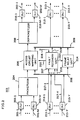
- FIG. 2 shows, in simplified block diagram form, the general architecture of nodes 101.
- the configuration of specific ones of nodes 101 may include an interface to at least one network facility and may not include any access facilities.
- a typical one of nodes 101 includes one or more receive access facilities 201-1 through 201-M, and a corresponding number of transmit access facilities 202-1 through 202-M.
- the signals received and transmitted on the access links may take any desired form.
- the access facility signals are non-packetized T-carrier in the known DS1 format.
- an access facility carries up to 24 access circuits.
- Signals obtained from receive access facilities 201-1 through 201-M are supplied via digital line interface (DLI) units 203-1 through 203-M, respectively, to packetizer 204.
- Each of digital line interfaces 203 are of a type well known in the art for interfacing the DS1 signals being supplied via the receive access facilities 201.
- Packetizer 204 forms incoming voice or data information into a packet format. Such packetizers are known in the art.
- the LAPD format is used for packetization.
- the LAPD layer 2 data unit is known as a frame
- the layer 3 data unit is known as a packet.
- the term "frame" is used instead of "packet”.
- the LAPD frames (FIG. 10) generated in packetizer 204 are supplied to access circuit mapping unit 205.
- Access circuit mapping unit 205 also obtains received frames from receive frame bus 206.
- remap control signals are supplied to access circuit mapping unit 205 via circuit path 220 from fault recovery unit 207.
- the remap control signals control remapping of access circuits carried on receive access facitilies 201 to virtual links carried on transmit network facilities 212, and the remapping of virtual links carried on receive network facilities 211 to the original access circuits carried on transmit access facilities 202.
- Access circuit mapping unit 205 yields so-called terminated frames which are supplied to depacketizer 208, and so-called transmit frames which are supplied to transmit frame bus 209.
- Depacketizer 208 reconstructs the voice or data digital signals from the terminated LAPD frames. These signals are supplied via digital line interface (DLI) units 210-1 through 210-M to transmit access facilities 202-1 through 202-M, respectively. Again, such digital line interface units and such depacketizers are known in the art.
- DLI digital line interface
- Received LAPD frames from receive network facilities 211-1 through 211-Y are supplied to digital line interface (DLI) units 213-1 through 213-Y, respectively.
- Each of digital line interface units 213 is of a type well known in the art for interfacing DS1 digital signals.
- each of digital line interface (DLI) units 213 generates a facility failure signal in well known fashion.
- the facility failure signals from digital line interfaces 213-1 through 213-Y each indicate whether a red, yellow, blue, or performance alarm has occurred and are supplied via circuit paths 217-1 through 217-Y, respectively, to fault recovery unit 207.
- Each of digital line interface units (DLI) 213-1 through 213-Y supplies the received LAPD frames to receive frame bus 206.
- the received frames can be of many types, including received fault indication messages as shown in FIGs. 11 and 12.
- Fault recovery unit 207 obtains the received fault indication messages from receive frame bus 206 via circuit path 218, in well known fashion. An equipment failure signal indicating the failure of any unit in this node in the path of any virtual circuit is supplied via circuit path 216 to fault recovery unit 207.
- Fault recovery unit 207 generates transmit fault indication messages which are supplied via circuit path 219 to transmit frame bus 209 and receive fault indication messages which are supplied via circuit path 221 to frame relay unit 214.
- Frame relay unit 214 obtains the received frames from receive frame bus 206. Additionally, frame relay unit 214 relays transmit frames from receive frame bus 206 to transmit frame bus 209.
- frame relay unit 214 employs the known LAPD frame relay procedure to remap these incoming frames into transmit frames that are supplied to transmit frame bus 209.
- the relayed frames include appropriate address mapping for each virtual circuit. That is to say, LAPD frames that are passing through this node are frame relayed from receive frame bus 206 to transmit frame bus 209.
- the operation of frame relay unit 214 is described below in conjunction with FIG. 9.
- the appropriate transmit frames are obtained from transmit frame bus 209 by digital line interface units (DLI) 215-1 through 215-Y and, then, supplied to transmit network facilities 212-1 through 212-Y, respectively. Pairs of receive network facilities 211-1 through 211-Y and transmit network facilities 212-1 through 212-Y form the network facilities (NFs) shown in FIG. 1.
- NFs network facilities
- Fault recovery unit 207 monitors for fault indication messages (FIGs. 11 and 12) on receive frame bus 206. This is achieved by monitoring received frames for those that match a prescribed format. To this end, control fields in the received frames are monitored to determine if the frame includes a control message.
- the prescribed format is the so-called LAPD XID frame format denoting fault indication messages for either a fault condition or a clear condition, as indicated in FIG. 11 and FIG. 12, respectively. As shown in FIG. 11 and FIG.
- the IDs (DLCIs) of the affected virtual circuits are included in fields of the information field of the LAPD frame, an indication (in this example, 10101111) that the LAPD frame is an XID frame is included in the XID field, an indication that this XID frame is a fault indication message is included in the FI field and an indication of whether the fault indication message denotes a fault or a clear condition is included in the GI field.
- an indication 11111010 in the GI field denotes a fault condition
- the indication 11110000 in the GI field denotes a clear condition.
- fault condition or clear condition indicated in the GI field is for all the affected virtual circuit DLCIs in the information field. It will be apparent to those skilled in the art that other signaling arrangements may equally be employed to indicate the presence of a fault indication message.
- fault recovery unit 207 either sends a remap control signal to access circuit mapping unit 205 causing it to switch a corresponding access circuit to a virtual link included in the alternate virtual circuit or sends a corresponding receive fault indication message via circuit path 221 to frame relay unit 214.
- frame relay unit 214 supplies the fault indication message to another node on a virtual link included in the primary virtual circuit.
- fault recovery unit 207 monitors for facility or equipment failures, and either orders access circuit mapping unit 205 via remap control signals to switch the affected access circuits to alternate virtual circuits and/or generates transmit fault indication messages to be passed via transmit frame bus 209 and appropriate ones digital line interface units 215-1 through 215-Y and transmit network facilities 212-1 through 212-Y, respectively, to other ones of nodes 101 in network 100 (FIG.1). Further details regarding operation of fault recovery unit 207 are discussed below in conjunction with FIGs. through 7.
- FIG. 3 depicts, in simplified block diagram form, details of fault recovery unit 207 of FIG. 2. Accordingly, shown are fault indication message receiver 301 and fault indication message generator 302.
- Fault indication message receiver 301 obtains received fault indication messages via circuit path 218 from receive frame bus 206. If the received fault indication message is for an access circuit in this node, the remap control signal for that access circuit is activated. If a received fault indication message is not for an access circuit in this node, it is supplied as an output unchanged to frame relay unit 214. The operation of fault indication message receiver 301 is shown in the flow chart of FIGs. 4 and 5 and described below.
- Fault indication message generator 302 is responsive to either a facility failure signal or an equipment failure signal becoming active or inactive.
- fault indication message generator 302 determines if the failure affects an access circuit terminated in this node. If an access circuit terminated in this node is affected, a remap control signal for the access circuit is activated. If the affected access circuit is not in this node, a transmit fault indication message including a fault indication (FIG. 11) is generated for the affected access circuit. Similarly, when the fault is cleared, either the remap control signal is deactivated or a transmit fault indication message including a clear indication (FIG. 12) is generated. Operation of fault indication message generator 302 is described below in conjunction with the flow chart shown in FIGS. 6 and 7.
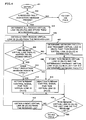
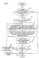
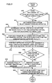
- FIGS. 4 and 5 when connected as shown, form a flow chart showing a sequence of operations effected in fault indication message receiver 301 of FIG. 3. Accordingly, the sequence is entered via step 401. Thereafter, conditional branch point 402 tests to determine if there is a received fault indication message on receive frame bus 206 (FIG. 2). If the test result is NO, the sequence is exited via step 403. If the test result in step 402 is YES, operational block 404 determines all the virtual link identifications from the received fault indication message and stores them in a received list. In the LAPD format the virtual link identification (ID) is known as the DLCI.
- ID virtual link identification
- Operational block 405 obtains a first receive virtual link ID (DLCI) from the received list. Then, conditional branch point 406 tests to determine if this receive virtual link ID (DLCI) is mapped to an access circuit in this node. If the test result in step 406 is NO, operational block 407 determines the transmit virtual link ID (DLCI) that this receive virtual link ID (DLCI) is connected to and the network facility that the transmit virtual link is on. Operational block 408 stores this receive virtual link ID (DLCI) and the determined virtual link ID (DLCI) in a list for the determined network facility. Then, conditional branch point 409 tests to determine if this receive virtual link ID (DLCI) is the last one stored in the received list. If the test result in step 409 is NO, control is supplied to operational block 410.
- DLCI receive virtual link ID
- step 406 if the test result is YES, this receive virtual link ID (DLCI) is mapped to an access circuit in this node, i.e., the virtual circuit is terminated at this node.
- Conditional branch point 411 tests to determine if the received fault indication message indicates the presence of a fault. or the clearing of a fault. If the test result in step 411 is YES, indicating the activation of a fault, operational block 412 supplies as an output an activated remap control signal for this receive virtual link ID (DLCI) to access circuit mapping unit 205 (FIG. 2). Thereafter, control is supplied to step 409.
- test result in step 411 is NO, indicating clearing of a fault
- operational block 413 supplies as an output a deactivated remap control signal for this receive virtual link ID (DLCI) to access circuit mapping unit 205 (FIG. 2). Thereafter, control is supplied to step 409.
- DLCI virtual link ID
- step 410 it causes a next virtual link ID (DLCI) to be obtaining from the received list. Then, appropriate ones of steps 406 through 413 are iterated until step 409 yields a YES result, indicating that the last virtual link ID (DLCI) has been reached in the received list.
- DLCI next virtual link ID
- Conditional branch point 414 tests to determine if any of the network lists formed in step 408 includes a transmit virtual link ID (DLCI). If the test result in step 414 is NO, the sequence is exited via step 403. If the test result in step 414 is YES, operational block 415 causes a first one of the network facility lists to be obtained. Then, operational block 416 generates a fault indication message including all the transmit virtual link IDs (DLCIs) in the current network facility list (FIG. 11). Operational block 417 selects at least one receive virtual link ID (DLCI) from the current network facility list for use as the address for the fault indication message generated in step 416. It is noted that frame relay unit 214 (FIG.
- test result in step 419 is YES
- sequence is exited via step 403.
- test result in step 419 is NO
- operational block 420 obtains a next network facility list from those generated in step 408. Thereafter, steps 416 through 420 are iterated until step 419 yields a YES result and, then, the sequence is exited via step 403.
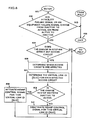
- conditional branch point 605 If the test result in step 604 is NO, control is supplied to conditional branch point 605 (FIG. 7). If the test result in step 604 is YES, operational block 606 determines which access circuits are affected. It is noted that more than one access circuit may be affected. Then, operational block 607 determines the virtual link ID (DLCI) for each affected access circuit. Conditional branch point 608 tests to determine if the change in state of either failure signal is from inactive to active. If the test result in step 608 is YES, operational block 609 activates the remap control signal for this virtual link ID (DLCI). Then, control is supplied to conditional branch point 605 (FIG. 7).
- DLCI virtual link ID
- step 608 If the test result in step 608 is NO, operational block 610 deactivates the remap control signal for this virtual link ID (DLCI). Thereafter, control is supplied to conditional branch point 605 (FIG. 7).
- Conditional branch point 605 tests to determine if the change in state of either failure signal affects any so-called frame relay connection, i.e., virtual link to virtual link connection. It is noted that an affected frame relay connection includes a faulted or cleared virtual link and a connected virtual link. If the test result in step 605 is NO, the sequence is exited via step 603 (FIG. 5). If the test result in step 605 is YES, operational block 611 determines which frame relay connections are affected by the fault.
- Operational block 612 determines the virtual link ID (DLCI) and the network facility of the connected virtual link for each affected virtual link.
- Operational block 613 causes the virtual link ID (DLCI) determined in step 612 to be stored in a list for the corresponding network facility.
- Operational block 614 causes a fault indication message to be generated for each network facility list.
- Each such fault indication message includes all the virtual link IDs (DLCIs) from the corresponding network facility list and uses one virtual link ID (DLCI) from the corresponding list as the message address. Again, a plurality of fault indication messages could be generated for each network facility list each using a different virtual link ID (DLCI) for its address.
- Conditional branch point 615 tests to determine whether the change in state of either failure signal is from inactive to active.
- step 615 If the test result in step 615 is YES, operational block 616 causes the fault indication message(s) generated in block 614 to indicate "fault” (FIG. 11). If the test result in step 615 is NO, operational block 617 causes the fault indication message generated in block 614 to indicate "clear” (FIG. 12). Thereafter, operational block 618 supplies as an output the fault indication message(s) to transmit frame bus 209 (FIG. 2). Then, the sequence is exited via step 603 (FIG. 6).
- FIG. 8 is a flow chart of a sequence of operations effected by access circuit mapping unit 205 of FIG. 2. Accordingly, the sequence is entered via step 801. Thereafter, conditional branch point 802 tests to determine if a received frame is present on receive frame bus 206 (FIG. 2). If the test result in step 802 is YES, operational block 803 determines the virtual link ID (DLCI) for the received frame. Conditional branch point 804 tests to determine if the remap control signal is active for this virtual link ID (DLCI). If the test result in 804 is YES, operational block 805 causes the virtual link ID (DLCI) determined in step 803 to be modified to a DLCI for the appropriate virtual link ID of the primary virtual circuit.
- DLCI virtual link ID
- test result in step 804 is NO, no action is taken to change the virtual link ID (DLCI) and operational block 806 supplies the received frame to depacketizer 208 (FIG. 2). Thereafter, the sequence is exited via step 807.
- conditional branch point 808 tests to determine if there is a generated frame from packetizer 204 (FIG. 2). If the test result in step 808 is NO, the sequence is exited via step 807. If the test result in step 808 is YES, operational block 809 determines the virtual link ID (DLCI) for the generated frame. Then, conditional branch point 810 tests to determine if the remap control signal is active for this virtual link ID (DLCI).
- operational block 811 changes the virtual link ID (DLCI) in the generated frame to the alternate virtual link ID (DLCI) for the appropriate virtual link in the alternate virtual circuit (FIG. 1). Then, operational block 812 supplies as an output the generated frame to transmit frame bus 209 (FIG. 2). Thereafter, the sequence is exited via step 807.
- the test result is NO, the generated frame DLCI is not changed and steps 812 and 807 are iterated.
- FIG. 9 is a flow chart of a sequence of operations effected in frame relay unit 214 of FIG. 2. This flow chart does not completely describe the LAPD frame relay function known to the art but only those functions necessary to this embodiment of the invention. Accordingly, the sequence is entered via step 901. Then, conditional branch point 902 tests to determine if there is a received frame on receive frame bus 206 (FIG. 2). If the test result in step 902 is NO, conditional branch point 903 tests to determine if there is a receive fault indication message on receive frame bus 206 (FIG. 2). If the result in step 903 is NO, the sequence is exited via step 904.
- operational block 905 determines the virtual link ID (DLCI) for the received frame.
- Operational block 906 determines the virtual link ID (DLCI) for the connected virtual link, i.e., the frame relay connection.
- Operational block 907 changes the virtual link ID (DLCI) of the received frame to the virtual link ID (DLCI) for the connected virtual link.
- Operational block 908 supplies as an output the modified "received" frame to the transmit frame bus 209 (FIG. 2). Thereafter, the sequence is exited by step 904.
Landscapes
- Engineering & Computer Science (AREA)
- Computer Networks & Wireless Communication (AREA)
- Signal Processing (AREA)
- Data Exchanges In Wide-Area Networks (AREA)
Abstract
Claims (16)
- Dispositif dans un noeud de commutation par paquets de reprise à la suite de pannes dans des chemins de transmission comportant au moins un circuit virtuel dans un réseau comportant une pluralité de noeuds de commutation par paquets, comportant
un moyen (DLI 213-1 - 213-Y) pour détecter des pannes dans n'importe quels chemins de transmission associés au noeud, chacun desdits chemins de transmission comportant au moins une installation de réseau transportant au moins un circuit virtuel,
le dispositif étant CARACTERISE PAR
un moyen (302 par l'intermédiaire de 602, 604, 606, 607) pour déterminer si un circuit virtuel affecté par une panne détectée se termine dans le noeud,
un moyen (302 par l'intermédiaire de 602, 604, 605, 611-614) pour générer un message d'indication de panne pour chaque installation de réseau transportant un circuit virtuel qui est affecté par la panne détectée et comportant une identité de chaque circuit virtuel affecté qui ne se termine pas dans le noeud et qui est transporté sur ladite installation de réseau,
un moyen (302 par l'intermédiaire de 618, 209) pour transmettre lesdits messages d'indication de pannes générés, chaque message d'indication de panne généré étant transmis sur au moins un des circuits virtuels affectés transportés par une installation de réseau correspondante loin de la panne à un quelconque autre noeud dans le réseau, et
un moyen (205, 209) pour commuter n'importe quels circuits virtuels affectés déterminés comme se terminant dans le noeud sur d'autres circuits virtuels associés pour la transmission à un noeud de destination. - Dispositif selon la revendication 1, comportant
un moyen (301) pour recevoir des messages d'indication de pannes comportant un autre moyen (301 par l'intermédiaire de 402-406, 411-413, 409, 410) pour déterminer si des circuits virtuels quelconques identifiés dans un message d'indication de panne reçu se terminent dans le noeud,
un autre moyen (301 par l'intermédiaire de 402-410, 414-420) pour générer un message d'indication de panne pour chaque installation de réseau comportant des circuits virtuels affectés par une panne détectée et ne se terminant pas dans le noeud, chacun desdits messages d'indication de pannes générés comportant une identité de chaque circuit virtuel affecté ne se terminant pas dans le noeud et étant transmis sur ladite installation de réseau, et
un autre moyen (301 par l'intermédiaire de 418, 214) pour transmettre lesdits messages d'indication de pannes générés par ledit second moyen de génération, chacun desdits messages d'indication de pannes générés étant transmis sur au moins un desdits circuits virtuels affectés sur une installation de réseau correspondante à un quelconque autre noeud dans le réseau. - Dispositif selon la revendication 2, dans lequel chacun desdits circuits virtuels comporte un premier circuit d'accès (201) à un noeud de départ, un second circuit d'accès (201) à un noeud d'arrivée et au moins une liaison virtuelle (VL).
- Dispositif selon la revendication 3, dans lequel chacun desdits messages d'indication de pannes reçus pour une installation de réseau correspondante comporte des identités de liaisons virtuelles dans des circuits virtuels correspondants étant transmis sur ladite installation de réseau correspondante, et ledit autre moyen pour déterminer comporte un moyen (301 par l'intermédiaire de 402-406, 411, 412) pour générer un signal de commande représentant si une liaison virtuelle identifiée dans le message d'indication de panne reçu est liée à un circuit d'accès dans le noeud et ledit moyen (205, 209) pour commuter est sensible audit signal de commande pour changer l'identité de ladite liaison virtuelle en une autre identité de liaison virtuelle quand ledit signal de commande indique que ladite liaison virtuelle est reliée à un circuit d'accès dans le noeud, dans lequel ledit circuit d'accès est relié à un autre circuit virtuel pour la transmission audit circuit d'accès de destination.
- Dispositif selon la revendication 3, dans lequel ledit moyen pour déterminer comporte un moyen (302 par l'intermédiaire de 604, 606) pour identifier des circuits d'accès dans le noeud qui sont affectés par la panne détectée, un moyen (302 par l'intermédiaire de 607) pour identifier une liaison virtuelle associée pour chaque circuit d'accès dans le noeud qui est affecté par la panne détectée et un moyen (302 par l'intermédiaire de 604-609) pour générer un premier signal de commande représentatif du fait qu'un circuit d'accès correspondant est relié à une liaison virtuelle qui est affectée par la panne détectée, et dans lequel ledit moyen pour commuter comporte un moyen (205 par l'intermédiaire de 808-811) sensible audit premier signal de commande pour changer l'identité de ladite liaison virtuelle associée au circuit d'accès identifié en une autre identité de liaison virtuelle, dans lequel ledit circuit d'accès est relié à un autre circuit virtuel.
- Dispositif selon la revendication 3, dans lequel chacun desdits circuits virtuels peut comporter une liaison virtuelle reliée à une autre liaison virtuelle dans un noeud, et ledit moyen pour générer un message d'indication de panne comporte un moyen (302 par l'intermédiaire de 602, 604, 605, 611-613) pour identifier une liaison virtuelle à laquelle une liaison virtuelle affectée par la panne détectée est reliée et un moyen (302 par l'intermédiaire de 614-616) pour inclure l'identité de la liaison virtuelle identifiée dans le message d'indication de panne généré pour l'installation de réseau correspondante ayant au moins un circuit virtuel affecté, et dans lequel ledit moyen (302 par l'intermédiaire de 618, 209) pour transmettre fournit ledit message d'indication de panne généré en guise de sortie sur au moins un circuit virtuel affecté transporté sur ladite installation de réseau correspondante.
- Dispositif selon la revendication 3, dans lequel ledit autre moyen pour générer comporte un moyen (301 par l'intermédiaire de 402-410) pour déterminer une identité d'une liaison virtuelle dans ledit message d'indication de panne reçu, un moyen (301-407) pour déterminer une identité d'une liaison virtuelle associée à laquelle ladite liaison virtuelle identifiée doit être connectée, un moyen (301-416) pour inclure l'identification de liaison virtuelle de la liaison virtuelle associée dans le message d'indication de panne, et dans lequel ledit autre moyen (301 par l'intermédiaire de 418, 214) pour transmettre comporte un moyen (301 par l'intermédiaire de 417, 418) pour fournir le message d'indication de panne comportant les identités de toutes les liaisons virtuelles associées en guise de sortie sur au moins un circuit virtuel affecté transporté sur ladite installation de réseau correspondante.
- Dispositif selon la revendication 3, dans lequel ledit message d'indication de panne comporte une trame comportant une pluralité de zones, une zone prédéterminée comportant les identités (DLCI) de toutes les liaisons virtuelles de circuits virtuels correspondants affectés par la panne détectée transportés par une installation de réseau correspondante et une zone (GI) comportant une indication de l'existence ou non d'une condition de panne.
- Dispositif selon la revendication 8, comportant en outre une zone (FI) dans ladite trame qui comporte une indication représentative du fait que la trame est un message d'indication de panne.
- Dispositif selon la revendication 9, dans lequel ladite trame est une trame LAPD XID ayant une zone (XID) comportant une indication que la trame est une trame XID.
- Procédé de reprise à la suite de pannes dans des chemins de transmission associés à un noeud de commutation par paquets comportant au moins un circuit virtuel associé à un noeud de commutation par paquets dans un réseau comportant une pluralité de noeuds de commutation par paquets, comportant l'étape de
détection de pannes (par l'intermédiaire de DLI 213-1 à 213-Y) dans n'importe quels chemins de transmission associés au noeud, chacun desdits chemins de transmission comportant au moins une installation de réseau transportant au moins un circuit virtuel,
le procédé étant CARACTERISE PAR
la détermination (par l'intermédiaire de 302, 602, 604, 606, 607) de la terminaison ou non dans le noeud d'un circuit virtuel affecté par une panne détectée,
la génération (par l'intermédiaire de 302, 602, 604, 605, 611-614) d'un message d'indication de panne pour chaque installation de réseau transportant un circuit virtuel qui est affecté par la panne détectée et comportant une identité de chaque circuit virtuel affecté ne se terminant pas dans le noeud et étant transporté sur ladite installation de réseau,
la transmission (par l'intermédiaire de 302, 618, 209) desdits messages d'indication de pannes générés, chaque message d'indication de panne généré étant transmis sur au moins un des circuits virtuels affectés transportés par une installation de réseau correspondante loin de la panne à un quelconque autre noeud dans le réseau, et
la commutation (par l'intermédiaire de 205, 209) de n'importe quels circuits virtuels affectés déterminés comme se terminant dans le noeud sur d'autres circuits virtuels associés pour la transmission vers un noeud de destination. - Procédé selon la revendication 11, comportant les étapes de
réception (par l'intermédiaire de 301) de messages d'indication de pannes comportant l'étape de détermination (par l'intermédiaire de 301, 402-406) de la terminaison ou non dans le noeud de circuits virtuels quelconques identifiés dans un message d'indication de panne reçu,
génération (par l'intermédiaire de 301, 402-410, 414-420) d'un message d'indication de panne pour chaque installation de réseau comportant des circuits virtuels affectés par une panne détectée et ne se terminant pas dans le noeud, chacun desdits messages d'indication de pannes générés comportant une identité de chaque circuit virtuel affecté ne se terminant pas dans le noeud et étant transmis sur ladite installation de réseau, et
transmission (par l'intermédiaire de 301, 418, 214) desdits messages d'indication de pannes, chacun desdits messages d'indication de pannes générés étant transmis sur au moins un desdits circuits virtuels affectés sur une installation de réseau correspondante à un quelconque autre noeud dans le réseau. - Procédé selon la revendication 12, dans lequel chacun desdits circuits virtuels comporte
un premier circuit d'accès (201) à un noeud de départ, un second circuit d'accès (201) à un noeud d'arrivée et au moins une liaison virtuelle (VL). - Procédé selon la revendication 13, dans lequel ledit message d'indication de panne comporte une trame comportant une pluralité de zones, une zone prédéterminée comportant les identités (DLCI) de toutes les liaisons virtuelles de circuits virtuels correspondants affectés par la panne détectée transportés par une installation de réseau correspondante et une zone (GI) comportant une indication de l'existence ou non d'une condition de panne.
- Procédé selon la revendication 14, dans lequel une zone (FI) dans ladite trame comporte une indication représentative du fait que la trame est un message d'indication de panne.
- Procédé selon la revendication 15, dans lequel ladite trame est une trame LAPD XID ayant une zone comportant une indication que la trame est une trame XID.
Applications Claiming Priority (3)
| Application Number | Priority Date | Filing Date | Title |
|---|---|---|---|
| US431796 | 1989-11-06 | ||
| US07/431,796 US5016243A (en) | 1989-11-06 | 1989-11-06 | Automatic fault recovery in a packet network |
| PCT/US1990/006546 WO1991007040A1 (fr) | 1989-11-06 | 1990-11-02 | Reparation automatique de derangements d'un reseau de transmission par paquets |
Publications (2)
| Publication Number | Publication Date |
|---|---|
| EP0452479A1 EP0452479A1 (fr) | 1991-10-23 |
| EP0452479B1 true EP0452479B1 (fr) | 1995-02-22 |
Family
ID=23713455
Family Applications (1)
| Application Number | Title | Priority Date | Filing Date |
|---|---|---|---|
| EP91900115A Expired - Lifetime EP0452479B1 (fr) | 1989-11-06 | 1990-11-02 | Reparation automatique de derangements d'un reseau de transmission par paquets |
Country Status (8)
| Country | Link |
|---|---|
| US (1) | US5016243A (fr) |
| EP (1) | EP0452479B1 (fr) |
| JP (1) | JP2533998B2 (fr) |
| AU (1) | AU626745B2 (fr) |
| CA (1) | CA2042402C (fr) |
| DE (1) | DE69017193T2 (fr) |
| IL (1) | IL96256A0 (fr) |
| WO (1) | WO1991007040A1 (fr) |
Cited By (1)
| Publication number | Priority date | Publication date | Assignee | Title |
|---|---|---|---|---|
| CN101610212B (zh) * | 2009-07-27 | 2012-12-12 | 迈普通信技术股份有限公司 | 实现数据平面可靠通信的方法和板卡 |
Families Citing this family (51)
| Publication number | Priority date | Publication date | Assignee | Title |
|---|---|---|---|---|
| US4993015A (en) * | 1989-11-06 | 1991-02-12 | At&T Bell Laboratories | Automatic fault recovery in a packet network |
| JPH04154242A (ja) * | 1990-10-17 | 1992-05-27 | Nec Corp | ネットワーク障害回復方式 |
| US6847611B1 (en) * | 1990-12-10 | 2005-01-25 | At&T Corp. | Traffic management for frame relay switched data service |
| US5159594A (en) * | 1990-12-31 | 1992-10-27 | At&T Bell Laboratories | Transparent communication of control information through a switching network |
| JP2752265B2 (ja) * | 1991-05-10 | 1998-05-18 | 株式会社東芝 | Lanからの切離し機能を持つ計算機システム |
| US5307354A (en) * | 1991-05-31 | 1994-04-26 | International Business Machines Corporation | Method and apparatus for remote maintenance and error recovery in distributed data processing networks |
| WO1992022971A1 (fr) * | 1991-06-18 | 1992-12-23 | Fujitsu Limited | Procede de determination d'un itineraire de remplacement |
| US5894547A (en) * | 1991-06-27 | 1999-04-13 | International Business Machines Corporation | Virtual route synchronization |
| US5416834A (en) * | 1991-12-30 | 1995-05-16 | At&T Corp. | Redirection of calls by a communication terminal |
| US5377262A (en) * | 1991-12-30 | 1994-12-27 | At&T Corp. | Telecommunication switching system having adaptive routing switching nodes |
| US5375167A (en) * | 1991-12-30 | 1994-12-20 | At&T Corp. | Telecommunication switching system having distributed dialing plan hierarchy |
| US5390242A (en) * | 1991-12-30 | 1995-02-14 | At&T Corp. | Rerouting in a distributed telecommunication system |
| US5386466A (en) * | 1991-12-30 | 1995-01-31 | At&T Corp. | Automatic initialization of a distributed telecommunication system |
| AU5684294A (en) * | 1992-12-03 | 1994-06-22 | Carnegie Wave Energy Limited | Method for on-line diagnosis for distributed network systems |
| CA2107757C (fr) * | 1992-12-18 | 1998-07-07 | Bruce Merrill Bales | Systeme de commutation a fonctions transparentes pour les telecommunications sans fil |
| US5390241A (en) * | 1992-12-18 | 1995-02-14 | At&T Corp. | Shared line appearance across a plurality of switching systems |
| US6181679B1 (en) | 1993-03-19 | 2001-01-30 | International Business Machines Corporation | Management of packet transmission networks |
| US5404350A (en) * | 1993-04-22 | 1995-04-04 | At&T Corp. | Routing calls destined for inaccessible destinations |
| US6771617B1 (en) | 1993-06-17 | 2004-08-03 | Gilat Satellite Networks, Ltd. | Frame relay protocol-based multiplex switching scheme for satellite mesh network |
| US5434850A (en) | 1993-06-17 | 1995-07-18 | Skydata Corporation | Frame relay protocol-based multiplex switching scheme for satellite |
| US5365512A (en) * | 1993-07-02 | 1994-11-15 | Ericsson Ge Mobile Communications Inc. | Multisite trunked RF communication system with reliable control messaging network |
| JP3095314B2 (ja) * | 1993-08-31 | 2000-10-03 | 株式会社日立製作所 | パス切替方式 |
| US5442624A (en) * | 1993-10-29 | 1995-08-15 | At&T Corp. | Dynamic access control for an ATM network |
| US5502757A (en) * | 1993-12-22 | 1996-03-26 | At&T Corp. | Location dependent service for a wireless telephone |
| FI95637C (fi) * | 1994-02-28 | 1996-02-26 | Nokia Telecommunications Oy | Menetelmä pakettimuotoisen datayhteyden reitin vaihtamiseksi |
| US5509004A (en) * | 1994-08-01 | 1996-04-16 | Motorola, Inc. | Communication method and network with multiple dynamic intraswitching |
| JPH08195745A (ja) * | 1995-01-13 | 1996-07-30 | Fujitsu Ltd | パス切替装置およびパス切替方法 |
| US5659542A (en) | 1995-03-03 | 1997-08-19 | Intecom, Inc. | System and method for signalling and call processing for private and hybrid communications systems including multimedia systems |
| US5687308A (en) * | 1995-06-07 | 1997-11-11 | Tandem Computers Incorporated | Method to improve tolerance of non-homogeneous power outages |
| GB9522639D0 (en) * | 1995-11-04 | 1996-01-03 | Plessey Telecomm | Encryption key management |
| US5878428A (en) * | 1995-11-20 | 1999-03-02 | International Business Machines Corporation | System, method, and article of manufacture for adding transactional recovery to a binary class in an object oriented system |
| US6108304A (en) * | 1996-03-08 | 2000-08-22 | Abe; Hajime | Packet switching network, packet switching equipment, and network management equipment |
| US5805569A (en) * | 1996-04-30 | 1998-09-08 | Telefonaktiebolaget Lm Ericsson | Packet data communications system having a malfunction list |
| US5922077A (en) * | 1996-11-14 | 1999-07-13 | Data General Corporation | Fail-over switching system |
| US5838660A (en) * | 1996-11-14 | 1998-11-17 | Mci Communications Corporation | Dynamic restoration process |
| US5923840A (en) * | 1997-04-08 | 1999-07-13 | International Business Machines Corporation | Method of reporting errors by a hardware element of a distributed computer system |
| US5968189A (en) * | 1997-04-08 | 1999-10-19 | International Business Machines Corporation | System of reporting errors by a hardware element of a distributed computer system |
| US6011780A (en) * | 1997-05-23 | 2000-01-04 | Stevens Institute Of Technology | Transparant non-disruptable ATM network |
| US6081524A (en) * | 1997-07-03 | 2000-06-27 | At&T Corp. | Frame relay switched data service |
| US6311288B1 (en) * | 1998-03-13 | 2001-10-30 | Paradyne Corporation | System and method for virtual circuit backup in a communication network |
| US6363051B1 (en) * | 1998-06-30 | 2002-03-26 | At&T Corp. | Method and apparatus for achieving fast reconnection of permanent virtal channels in a frame relay network |
| US6999459B1 (en) * | 1998-07-10 | 2006-02-14 | Pluris, Inc. | System and method for facilitating recovery from communication link failures in a digital data network |
| EP0986226B1 (fr) * | 1998-09-11 | 2007-01-17 | Hitachi, Ltd. | Appareil de communication par paquets IP |
| US6549533B1 (en) * | 1998-12-30 | 2003-04-15 | Objective Systems Integrators | Managing switched virtual circuits in a network |
| US6653434B2 (en) * | 2000-12-29 | 2003-11-25 | General Electric Company | Process for the production of polycarbonate |
| US7206281B2 (en) * | 2002-05-03 | 2007-04-17 | Ciena Corporation | Calculating physical routes in a communication network |
| US7986618B2 (en) * | 2002-06-12 | 2011-07-26 | Cisco Technology, Inc. | Distinguishing between link and node failure to facilitate fast reroute |
| US8520507B1 (en) | 2004-03-08 | 2013-08-27 | Extreme Networks, Inc. | Ethernet automatic protection switching |
| US7606240B1 (en) | 2005-06-16 | 2009-10-20 | Extreme Networks | Ethernet automatic protection switching |
| KR100780359B1 (ko) * | 2006-09-27 | 2007-11-30 | 삼성전자주식회사 | 유엠에이 네트워크에서 연결 오류 처리 장치 및 방법 |
| US9204269B1 (en) * | 2012-07-02 | 2015-12-01 | CSC Holdings, LLC | Method and system for service continuity, network preference, and reporting logic with SMS services |
Family Cites Families (10)
| Publication number | Priority date | Publication date | Assignee | Title |
|---|---|---|---|---|
| BE871518A (nl) * | 1978-10-25 | 1979-04-25 | Bell Telephone Mfg | Gegevenscommunicatie-en gegevensverwerkend stelsel. |
| US4777595A (en) * | 1982-05-07 | 1988-10-11 | Digital Equipment Corporation | Apparatus for transferring blocks of information from one node to a second node in a computer network |
| US4593154A (en) * | 1983-07-08 | 1986-06-03 | Nissan Motor Company, Limited | Loop-type data transmission/reception network |
| US4550397A (en) * | 1983-12-16 | 1985-10-29 | At&T Bell Laboratories | Alternate paths in a self-routing packet switching network |
| DE3687400T2 (de) * | 1985-11-04 | 1993-07-15 | Ibm | Digitale nachrichtenuebertragungsnetzwerke und aufbau von uebertragungswegen in diesen netzwerken. |
| US4679189A (en) * | 1985-11-27 | 1987-07-07 | American Telephone And Telegraph Company | Alternate routing arrangement |
| DE3788577T2 (de) * | 1986-01-09 | 1994-07-07 | Nippon Electric Co | Paketvermitteltes Fernmeldenetz mit parallelen virtuellen Verbindungen zur Umweglenkung von Nachrichtenpaketen. |
| US4703477A (en) * | 1986-02-28 | 1987-10-27 | American Telephone And Telegraph Company At&T Bell Laboratories | Packet information field data format |
| US4920529A (en) * | 1987-02-27 | 1990-04-24 | Hitachi, Ltd. | Network control method and apparatus therefor |
| US4999829A (en) * | 1989-11-06 | 1991-03-12 | At&T Bell Laboratories | Automatic fault recovery in a packet network |
-
1989
- 1989-11-06 US US07/431,796 patent/US5016243A/en not_active Expired - Lifetime
-
1990
- 1990-11-02 WO PCT/US1990/006546 patent/WO1991007040A1/fr not_active Ceased
- 1990-11-02 JP JP3500823A patent/JP2533998B2/ja not_active Expired - Lifetime
- 1990-11-02 AU AU68886/91A patent/AU626745B2/en not_active Ceased
- 1990-11-02 CA CA002042402A patent/CA2042402C/fr not_active Expired - Fee Related
- 1990-11-02 EP EP91900115A patent/EP0452479B1/fr not_active Expired - Lifetime
- 1990-11-02 DE DE69017193T patent/DE69017193T2/de not_active Expired - Lifetime
- 1990-11-06 IL IL96256A patent/IL96256A0/xx unknown
Cited By (1)
| Publication number | Priority date | Publication date | Assignee | Title |
|---|---|---|---|---|
| CN101610212B (zh) * | 2009-07-27 | 2012-12-12 | 迈普通信技术股份有限公司 | 实现数据平面可靠通信的方法和板卡 |
Also Published As
| Publication number | Publication date |
|---|---|
| AU6888691A (en) | 1991-05-31 |
| CA2042402A1 (fr) | 1991-05-07 |
| IL96256A0 (en) | 1991-08-16 |
| DE69017193D1 (de) | 1995-03-30 |
| AU626745B2 (en) | 1992-08-06 |
| JP2533998B2 (ja) | 1996-09-11 |
| WO1991007040A1 (fr) | 1991-05-16 |
| EP0452479A1 (fr) | 1991-10-23 |
| CA2042402C (fr) | 1996-11-19 |
| DE69017193T2 (de) | 1995-06-29 |
| JPH05502347A (ja) | 1993-04-22 |
| US5016243A (en) | 1991-05-14 |
Similar Documents
| Publication | Publication Date | Title |
|---|---|---|
| EP0452479B1 (fr) | Reparation automatique de derangements d'un reseau de transmission par paquets | |
| EP0452466B1 (fr) | Reparation automatique de derangements d'un reseau de transmission par paquets | |
| EP0452487B1 (fr) | Retour a la normale automatique apres derangements dans un reseau de transmission par paquets | |
| US6898630B2 (en) | Network management system utilizing notification between fault manager for packet switching nodes of the higher-order network layer and fault manager for link offering nodes of the lower-order network layer | |
| JP4687176B2 (ja) | パケット中継装置 | |
| US7596094B2 (en) | System and method for transmission of operations, administration, and maintenance packets between ATM and switching networks upon failures | |
| US7126921B2 (en) | Packet network providing fast distribution of node related information and a method therefor | |
| EP2074752B1 (fr) | Principes de résilience dans des réseaux de communications en mode connexion | |
| US8917592B2 (en) | Communication apparatus, system, and method | |
| CA2337068A1 (fr) | Systeme et procede assurant le retablissement de liaisons de communication defaillantes dans un reseau de donnees numeriques | |
| US20100150160A1 (en) | Interworking oam between ethernet and atm/frame relay networks | |
| CN102857316B (zh) | 一种实现源环网保护的方法及系统 | |
| WO2001067677A2 (fr) | Acheminement de couche 3 dans des reseaux a retablissement automatique | |
| KR101726264B1 (ko) | 이기종 패킷전달망간 연동을 위한 통합 네트워크 관리 시스템 및 그 방법 | |
| JPH06318953A (ja) | 発ノード押し戻しによるデータ迂回方式 |
Legal Events
| Date | Code | Title | Description |
|---|---|---|---|
| PUAI | Public reference made under article 153(3) epc to a published international application that has entered the european phase |
Free format text: ORIGINAL CODE: 0009012 |
|
| 17P | Request for examination filed |
Effective date: 19910702 |
|
| AK | Designated contracting states |
Kind code of ref document: A1 Designated state(s): DE FR GB IT |
|
| EL | Fr: translation of claims filed | ||
| 17Q | First examination report despatched |
Effective date: 19931126 |
|
| RAP3 | Party data changed (applicant data changed or rights of an application transferred) |
Owner name: AT&T CORP. |
|
| GRAA | (expected) grant |
Free format text: ORIGINAL CODE: 0009210 |
|
| AK | Designated contracting states |
Kind code of ref document: B1 Designated state(s): DE FR GB IT |
|
| ITF | It: translation for a ep patent filed | ||
| ET | Fr: translation filed | ||
| REF | Corresponds to: |
Ref document number: 69017193 Country of ref document: DE Date of ref document: 19950330 |
|
| PLBE | No opposition filed within time limit |
Free format text: ORIGINAL CODE: 0009261 |
|
| STAA | Information on the status of an ep patent application or granted ep patent |
Free format text: STATUS: NO OPPOSITION FILED WITHIN TIME LIMIT |
|
| 26N | No opposition filed | ||
| REG | Reference to a national code |
Ref country code: GB Ref legal event code: IF02 |
|
| PG25 | Lapsed in a contracting state [announced via postgrant information from national office to epo] |
Ref country code: IT Free format text: LAPSE BECAUSE OF NON-PAYMENT OF DUE FEES Effective date: 20051102 |
|
| PGFP | Annual fee paid to national office [announced via postgrant information from national office to epo] |
Ref country code: DE Payment date: 20091120 Year of fee payment: 20 |
|
| PGFP | Annual fee paid to national office [announced via postgrant information from national office to epo] |
Ref country code: FR Payment date: 20091201 Year of fee payment: 20 Ref country code: GB Payment date: 20091119 Year of fee payment: 20 |
|
| REG | Reference to a national code |
Ref country code: GB Ref legal event code: PE20 Expiry date: 20101101 |
|
| PG25 | Lapsed in a contracting state [announced via postgrant information from national office to epo] |
Ref country code: GB Free format text: LAPSE BECAUSE OF EXPIRATION OF PROTECTION Effective date: 20101101 |
|
| PG25 | Lapsed in a contracting state [announced via postgrant information from national office to epo] |
Ref country code: DE Free format text: LAPSE BECAUSE OF EXPIRATION OF PROTECTION Effective date: 20101102 |