EP0452561A2 - Einrichtung zur elektrischen Erwärmung - Google Patents
Einrichtung zur elektrischen Erwärmung Download PDFInfo
- Publication number
- EP0452561A2 EP0452561A2 EP90125037A EP90125037A EP0452561A2 EP 0452561 A2 EP0452561 A2 EP 0452561A2 EP 90125037 A EP90125037 A EP 90125037A EP 90125037 A EP90125037 A EP 90125037A EP 0452561 A2 EP0452561 A2 EP 0452561A2
- Authority
- EP
- European Patent Office
- Prior art keywords
- outer housing
- current path
- heating device
- path element
- furnace
- Prior art date
- Legal status (The legal status is an assumption and is not a legal conclusion. Google has not performed a legal analysis and makes no representation as to the accuracy of the status listed.)
- Withdrawn
Links
Images


Classifications
-
- F—MECHANICAL ENGINEERING; LIGHTING; HEATING; WEAPONS; BLASTING
- F27—FURNACES; KILNS; OVENS; RETORTS
- F27D—DETAILS OR ACCESSORIES OF FURNACES, KILNS, OVENS OR RETORTS, IN SO FAR AS THEY ARE OF KINDS OCCURRING IN MORE THAN ONE KIND OF FURNACE
- F27D99/00—Subject matter not provided for in other groups of this subclass
- F27D99/0001—Heating elements or systems
- F27D99/0006—Electric heating elements or system
-
- F—MECHANICAL ENGINEERING; LIGHTING; HEATING; WEAPONS; BLASTING
- F27—FURNACES; KILNS; OVENS; RETORTS
- F27B—FURNACES, KILNS, OVENS OR RETORTS IN GENERAL; OPEN SINTERING OR LIKE APPARATUS
- F27B5/00—Muffle furnaces; Retort furnaces; Other furnaces in which the charge is held completely isolated
- F27B5/06—Details, accessories or equipment specially adapted for furnaces of these types
- F27B5/14—Arrangements of heating devices
-
- H—ELECTRICITY
- H05—ELECTRIC TECHNIQUES NOT OTHERWISE PROVIDED FOR
- H05B—ELECTRIC HEATING; ELECTRIC LIGHT SOURCES NOT OTHERWISE PROVIDED FOR; CIRCUIT ARRANGEMENTS FOR ELECTRIC LIGHT SOURCES, IN GENERAL
- H05B3/00—Ohmic-resistance heating
- H05B3/62—Heating elements specially adapted for furnaces
- H05B3/64—Heating elements specially adapted for furnaces using ribbon, rod, or wire heater
Definitions
- the present invention provides a novel electrified single-ended tube heating device which can be replaceably disposed within a carburizing integral quench furnace. Furthermore, the present invention relates to electric heating furnaces, and more particularly to electrical resistance heating type heat treating or melting furnaces in which the heating device is incorporated.
- Another difficulty encountered is control of the desired heat distribution in the furnace and particularly in a heat treating furnace in which hot gases in the treating chamber are circulated by gravity or by a fan or the like.
- the corrugated heating elements resulted in a maintenance problem, wherein replacement required entering the furnace and removing the elements from the furnace walls.
- U-tube heating elements were developed.
- a typical U-tube heating element is disclosed in U.S. Patent No. 4,332,552 (Seelandt), which issued on June 1, 1982.
- the U-tube heating elements solved the maintenance problems associated with the corrugated heating elements by permitting removal of the elements through the roof of the furnace.
- the U-tube heating element operates on extremely low voltage, which permitted disposition of the element directly in a carbonaceous atmosphere. Since there is no need to isolate the element from the atmosphere, the element is free to radiate directly within the heat chamber, thereby lowering element operating temperatures.
- the elements are plug-mounted in the roof for ease of service. Four elements are utilized, two per sidewall, for maximum radiating area and extend above, below and beyond the workpiece.
- U-tube heating elements require very large openings in the furnace roof and are not interchangeable with gas fired, "single-ended" radiant tubes; that is to say, straight tubes requiring only that a single small roof opening be provided, contrasted with U-shaped elements. Therefore, the present inventor undertook the development of a unique electrified single-ended tube heating device which is easily replaceable and can be interchanged with the aforesaid gas fired, single-ended radiant tubes.
- the electrified single-ended tube heating device of the present invention is a low voltage heating device which permits operation directly in a carbonaceous atmosphere. Its unique design also facilitates field replacement or conversion to gas fired single-ended radiant tubes while minimizing the size of the roof openings.
- the present invention also provides many additional advantages which shall become apparent as described below.
- a low voltage electric heating device for application in a furnace which comprises: a cylindrical outer housing or sleeve replaceably disposed within a carburizing integral quench furnace and, in one preferred embodiment, electrically connected to a first electric terminal; and at least one low resistance current path element disposed within the outer housing, the current path element being electrically connected to a second electric terminal and electrically insulated from the outer housing.
- the electric heating device may include a first current path element and a second current path element disposed within the outer housing or sleeve.
- the first current path element preferably traverses, or is coextensive with, the entire length of the outer housing and the second current path element traverses only a portion of the outer housing, the second element being electrically connected to the sleeve at the second element's lowermost point.
- the outer housing or sleeve radiates heat directly, and selectively, into the carbonaceous atmosphere during the processing of the workpiece.
- selective is meant that the radiated heat is concentrated where it is most needed; namely in an area removed from the entry opening in the furnace roof, rather than being concentrated close to the opening.
- Fig. 1 depicts a carburizing integral quench furnace assembly 1 which includes an exterior panel 2 and an interior panel 3.
- Panels 2 and 3 are typically formed of a fibrous material.
- the panels serve to enclose the furnace chamber 4 into which is inserted at least one single-ended electric heating device 5.
- the panels (2,3) are fitted within a steel or other type of furnace shell 6 so as to form a space 7 therebetween on the order of one inch, although the exact dimensioning will depend on the type of furnace and its corresponding dimensions.
- Space 7 may either be left unfilled or may have inserted therein a blanket of fibrous material (not shown) which is receptive to the passage of gas therethrough.
- the side and rear wall assemblies 8 include a rectangularly shaped outer frame 9, a center bar (not shown) and a plurality of cross bars 10 which interconnect the center bar with frame 9.
- Wall assembly 8 is constructed by securing blocks of fibrous material to the center bar and cross bars 10 by use of clips, retainers, bolts or other conventional securing members so as to support at least an exterior Panel 2 and, under some circumstances, an interior panel 3, with a blanket of insulating material (not shown) being inserted between adjacent panels.
- spacers 12 in the form of bolts and threaded rods can be used to either secure panel 2 to furnace shell 6 or to assure that proper spacing to form space 7 is provided.
- Furnace shell 6 also includes an outwardly extending flange 14 for cooperation with roof assembly 15 which also includes a frame 9 similar to the wall assemblies for securing exterior panel 2 and interior panel 3 thereto.
- Roof assembly 15 includes a plurality of tapered openings 30 within which heating device 5 is mounted.
- Reference number 34 denotes an opening in roof assembly 15 for mounting of a gas circulation fan (not shown).
- Door assembly 38 includes a plurality of pins 39 attached thereto for cooperating with the furnace assembly.
- Floor assembly 40 includes a floor panel 42 of fibrous material mounted on a plurality of layers of brick insulation 44.
- Floor assembly 40 also includes a furnace snake chain guide assembly 52 used to transfer steel or other workpieces into furnace chamber 4.
- Roller rails 54 are also provided so as to assist in transferring the workpiece into furnace chamber 4 with cast rollers 56 being mounted on roller rails 54.
- Floor assembly 40 is provided with a rail support 60 upon which roller rails 54 are mounted.
- Reference number 46 designates a first source of purging gas (i.e., nitrogen is commonly used but other types of inert gases are acceptable) which may be supplied to furnace chamber 4.
- Reference number 48 denotes a second source of purging gas which can be supplied to space 7 formed between panel 2 and furnace shell 6.
- the furnace assembly 1 thus serves to provide a furnace chamber 4 which, during purging operation, is heated by heating device 5 to a temperature between 500 and 2000°F such that purging gas is introduced from the first source 46 which may include any inert gas.
- the purging gas forms an enriched endothermic atmosphere within the furnace chamber and is circulated about the furnace by operation of a gas circulating fan (not shown).
- the protective atmosphere within furnace chamber 4 is also subjected to a pressure which is approximately 0.2 ounces above atmospheric pressure.
- a corresponding auxiliary gas purge can also be accomplished by the introduction of nitrogen or a similar type gas under pressure approximately 0.2 ounces or more above atmospheric pressure within space 7 via secondary gas source 48.
- the nitrogen gas under pressure serves to assist purging of the furnace itself by keeping the exterior surface of exterior panel 2 at a higher temperature than is possible in a conventional furnace and purges water vapor and air by forcing the same towards the furnace chamber 4 by application of heat.
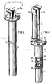
- a low voltage electric heating device 5 comprises a cylindrical outer housing or sleeve 70 replaceably disposed within furnace assembly 1 and electrically connected to a three phase system by way of a first electric connector 71.
- a first low resistance current path element 72 and a second current path element 74 are disposed within outer housing or sleeve 70.
- the current path elements (72,74) are independently electrically connected to the system by way of a dual electric connector 75, being electrically insulated from each other and outer housing 70.
- First current path element 72 preferably traverses, or is coextensive with, the entire length of outer housing 70, Fig. 4, whereas second current path element 74 traverses only a portion thereof.
- Cylindrical outer housing 70 is provided at its lower end with a disk-like portion 85 having an opening 86 such that first current path element 72 may, while making electrical contact with disk 85, conveniently extend beyond the confines of outer housing 70.
- Cylindrical outer housing 70 may also include a slot 76 about its sidewall such that a lower end of second current path element 74 is exposed to the carbonaceous atmosphere which surrounds outer housing 70.
- first current path element 72 is preferably rectangular in cross-section throughout, whereas second current path element 74 is substantially semicircular in cross-section for most of its length. As will be appreciated, the reason for this configuration is so that element 74 will fit within the circumference of tube or sleeve 70.
- Outer sleeve 70 may also include a guide bracket 78 capable of preventing shorting and also capable of insulating first current path element 72 from second current path element 74.
- Guide bracket 78 is preferably formed from a ceramic material.
- Fig. 4 is a cross-sectional view of heating device 5.
- the low resistance current path elements (72,74) are insulated from each other and outer housing 70 by insulation 80.
- Insulation 80 is typically a loose fiber. When multiple current path bars or elements are used, they typically have a gap therebetween of approximately 1/4".
- Cylindrical outer sleeve or tube 70 preferably comprises a first tubular member 82 having a flanged end, and a second tubular member 84 connected to first tubular member 82 by any conventional means. These tubular members are provided with a slot 76 which permits a lower shoulder portion 76A of second current path element 74 to be in electrical contact with tube 70 so that a complete series circuit path is established from 74, then by way of the lower part of tube 70, and return through metallic disk 85 and element 72. Second tubular member 84 includes an opening 86 at one end thereof such that guide disk 85 may be fitted therein and make electrical contact with element 72.
- Heating device 5 functions by having the electric current from the AC source 73 passed through the described circuit, including tube 70, so that the heat required by the furnace is principally radiated from the lower part of tube 70, which has a relatively large resistance R, compared with the smaller resistances r and r' respectively of elements 72 and 74.
- Fig. 5 is a top plan view along line 5-5 of Fig. 4, in which first current path element 72 is disposed in the center of outer housing 70 and second current path element 74 is disposed nearer to one side of tube 70.
- Fig. 6 is a cross-sectional view along line 6-6 of Fig. 4 and depicts the semicircular and rectangular shapes of element 74 and 72, respectively.
- Fig. 7 is a cross-sectional view along line 7-7 of Fig. 4 and depicts the positioning of element 74 within slot 76.
- Fig. 8 is a cross-sectional view along line 8-8 of Fig. 4, wherein element 72 is contained within tubular member 84.
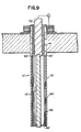
- FIG. 9 there will be seen an alternate preferred embodiment of the heating device in accordance with the present invention. Similar numerals in the form of prime numerals have been applied to this figure.
- the outer housing or sleeve 70' comprises two tubular members 82' and 84' suitably connected at adjacent ends, as was the case before.
- a much lower resistance R1 is chosen for the higher tubular member 82'; and a much higher resistance R2 for the lower tubular member 84'.
- a cylindrical ceramic insulator 90' is located at the upper part of device 5', disposed between element 72' and tubular member 82'.
Landscapes
- Engineering & Computer Science (AREA)
- Mechanical Engineering (AREA)
- General Engineering & Computer Science (AREA)
- Furnace Details (AREA)
- Resistance Heating (AREA)
Applications Claiming Priority (2)
| Application Number | Priority Date | Filing Date | Title |
|---|---|---|---|
| US51025790A | 1990-04-17 | 1990-04-17 | |
| US510257 | 1990-04-17 |
Publications (2)
| Publication Number | Publication Date |
|---|---|
| EP0452561A2 true EP0452561A2 (de) | 1991-10-23 |
| EP0452561A3 EP0452561A3 (en) | 1992-11-19 |
Family
ID=24029996
Family Applications (1)
| Application Number | Title | Priority Date | Filing Date |
|---|---|---|---|
| EP19900125037 Withdrawn EP0452561A3 (en) | 1990-04-17 | 1990-12-20 | Electric heating device |
Country Status (2)
| Country | Link |
|---|---|
| EP (1) | EP0452561A3 (de) |
| JP (1) | JPH0794262A (de) |
Cited By (2)
| Publication number | Priority date | Publication date | Assignee | Title |
|---|---|---|---|---|
| EP0752568A3 (de) * | 1995-07-06 | 1999-05-12 | Kanthal Ab | Elektrischen Ofen und Verfahren seiner Verwendung |
| CN104694715A (zh) * | 2015-01-19 | 2015-06-10 | 苏州新长光热能科技有限公司 | 有色金属热处理电炉的电加热装置 |
Family Cites Families (6)
| Publication number | Priority date | Publication date | Assignee | Title |
|---|---|---|---|---|
| GB153661A (en) * | 1919-08-09 | 1920-11-09 | Gen Electric | Improvements in and relating to electric heating units |
| CH250201A (de) * | 1942-04-28 | 1947-08-15 | Gerecke Eduard | Vakuumhochtemperaturofen mit elektrischer Widerstandsheizung. |
| FR1315187A (fr) * | 1961-12-08 | 1963-01-18 | Fours électriques tubulaires perfectionnés | |
| US3764718A (en) * | 1972-01-27 | 1973-10-09 | Dravo Corp | Vacuum furnace with an electric heater assembly |
| US4090054A (en) * | 1976-10-12 | 1978-05-16 | Brown Boveri Corporation | Electrical preheating apparatus |
| US4080510A (en) * | 1976-11-18 | 1978-03-21 | Btu Engineering Corporation | Silicon carbide heater |
-
1990
- 1990-12-20 EP EP19900125037 patent/EP0452561A3/en not_active Withdrawn
-
1991
- 1991-04-15 JP JP8223591A patent/JPH0794262A/ja active Pending
Cited By (2)
| Publication number | Priority date | Publication date | Assignee | Title |
|---|---|---|---|---|
| EP0752568A3 (de) * | 1995-07-06 | 1999-05-12 | Kanthal Ab | Elektrischen Ofen und Verfahren seiner Verwendung |
| CN104694715A (zh) * | 2015-01-19 | 2015-06-10 | 苏州新长光热能科技有限公司 | 有色金属热处理电炉的电加热装置 |
Also Published As
| Publication number | Publication date |
|---|---|
| JPH0794262A (ja) | 1995-04-07 |
| EP0452561A3 (en) | 1992-11-19 |
Similar Documents
| Publication | Publication Date | Title |
|---|---|---|
| FI85386B (fi) | Vakuumugn foer vaermebehandling av metallkroppar. | |
| JPH0772668B2 (ja) | 高い強さの赤外線熱処理装置 | |
| NO153415B (no) | Kontaktelektrodeanordning for lysbue- eller motstandssmelteovner. | |
| US4011395A (en) | Electric furnace heater | |
| US4612651A (en) | Heat treating furnace with heating element hangers and radiation shield spacers | |
| US4093816A (en) | Furnace heating apparatus | |
| EP0452561A2 (de) | Einrichtung zur elektrischen Erwärmung | |
| GB1087013A (en) | Vacuum furnace | |
| US5097114A (en) | Low-voltage heating device | |
| ES275029U (es) | Horno de resistencia electrica perfeccionado. | |
| US4101724A (en) | Furnace conversion method and apparatus | |
| US5473141A (en) | Radiant tube heating assembly | |
| US4327901A (en) | Melt and hold furnace for non-ferrous metals | |
| KR100484562B1 (ko) | 롤러하스형연속글라스기판봉착로 | |
| KR0142908B1 (ko) | 유도자의 극을 보호하기 위한 장치와 이 장치를 구비한 유도자 | |
| EP0467898B1 (de) | Vakuumofen | |
| JP7081029B1 (ja) | 超高温加熱炉の電極装置 | |
| US6111908A (en) | High temperature vacuum heater supporting mechanism with cup shaped shield | |
| JPS59194392A (ja) | 高温法用電極およびその使用法 | |
| CN114923343A (zh) | 一种烧结炉发热体的分区布置方法 | |
| US1839613A (en) | Electric furnace | |
| CA1105976A (en) | Electric furnace heater assembly | |
| US20110114621A1 (en) | Retort Furnace for Heat Treating Metal Workpieces | |
| JPH10158728A (ja) | 通電加熱方法 | |
| RU32953U1 (ru) | Электронагреватель |
Legal Events
| Date | Code | Title | Description |
|---|---|---|---|
| PUAI | Public reference made under article 153(3) epc to a published international application that has entered the european phase |
Free format text: ORIGINAL CODE: 0009012 |
|
| AK | Designated contracting states |
Kind code of ref document: A2 Designated state(s): AT DE FR GB IT |
|
| PUAL | Search report despatched |
Free format text: ORIGINAL CODE: 0009013 |
|
| AK | Designated contracting states |
Kind code of ref document: A3 Designated state(s): AT DE FR GB IT |
|
| 17P | Request for examination filed |
Effective date: 19930518 |
|
| 17Q | First examination report despatched |
Effective date: 19940831 |
|
| STAA | Information on the status of an ep patent application or granted ep patent |
Free format text: STATUS: THE APPLICATION IS DEEMED TO BE WITHDRAWN |
|
| 18D | Application deemed to be withdrawn |
Effective date: 19950313 |