EP0452582A1 - Verfahren und Vorrichtung zur Verhinderung von Spannungsrisskorrosion - Google Patents
Verfahren und Vorrichtung zur Verhinderung von Spannungsrisskorrosion Download PDFInfo
- Publication number
- EP0452582A1 EP0452582A1 EP90304303A EP90304303A EP0452582A1 EP 0452582 A1 EP0452582 A1 EP 0452582A1 EP 90304303 A EP90304303 A EP 90304303A EP 90304303 A EP90304303 A EP 90304303A EP 0452582 A1 EP0452582 A1 EP 0452582A1
- Authority
- EP
- European Patent Office
- Prior art keywords
- workpiece
- radiant heat
- set forth
- stress
- welded joint
- Prior art date
- Legal status (The legal status is an assumption and is not a legal conclusion. Google has not performed a legal analysis and makes no representation as to the accuracy of the status listed.)
- Withdrawn
Links
- 230000007797 corrosion Effects 0.000 title claims abstract description 17
- 238000005260 corrosion Methods 0.000 title claims abstract description 17
- 238000000034 method Methods 0.000 title claims abstract description 16
- 230000002401 inhibitory effect Effects 0.000 title claims abstract 5
- 238000005336 cracking Methods 0.000 title abstract description 10
- 229910000831 Steel Inorganic materials 0.000 claims abstract description 15
- 239000010959 steel Substances 0.000 claims abstract description 15
- 239000010935 stainless steel Substances 0.000 claims abstract description 12
- 229910001220 stainless steel Inorganic materials 0.000 claims abstract description 12
- 239000002826 coolant Substances 0.000 claims abstract description 7
- 239000012530 fluid Substances 0.000 claims abstract description 6
- 230000035882 stress Effects 0.000 claims description 37
- 238000001816 cooling Methods 0.000 claims description 4
- 230000001105 regulatory effect Effects 0.000 claims description 4
- 230000008646 thermal stress Effects 0.000 claims description 4
- 239000012809 cooling fluid Substances 0.000 claims 5
- 230000006835 compression Effects 0.000 claims 1
- 238000007906 compression Methods 0.000 claims 1
- 239000012141 concentrate Substances 0.000 claims 1
- 238000010438 heat treatment Methods 0.000 description 25
- 230000009467 reduction Effects 0.000 description 6
- 239000000919 ceramic Substances 0.000 description 5
- 238000011065 in-situ storage Methods 0.000 description 5
- 230000006698 induction Effects 0.000 description 5
- 239000000463 material Substances 0.000 description 4
- 229910000963 austenitic stainless steel Inorganic materials 0.000 description 3
- 238000009826 distribution Methods 0.000 description 3
- 238000009434 installation Methods 0.000 description 3
- 239000012212 insulator Substances 0.000 description 3
- 238000003466 welding Methods 0.000 description 3
- 229910045601 alloy Inorganic materials 0.000 description 2
- 239000000956 alloy Substances 0.000 description 2
- 239000003638 chemical reducing agent Substances 0.000 description 2
- 238000010276 construction Methods 0.000 description 2
- 239000000498 cooling water Substances 0.000 description 2
- 238000010586 diagram Methods 0.000 description 2
- 230000008030 elimination Effects 0.000 description 2
- 238000003379 elimination reaction Methods 0.000 description 2
- 229910052751 metal Inorganic materials 0.000 description 2
- 239000002184 metal Substances 0.000 description 2
- XLYOFNOQVPJJNP-UHFFFAOYSA-N water Substances O XLYOFNOQVPJJNP-UHFFFAOYSA-N 0.000 description 2
- 206010070834 Sensitisation Diseases 0.000 description 1
- 230000006978 adaptation Effects 0.000 description 1
- 238000005275 alloying Methods 0.000 description 1
- 238000000137 annealing Methods 0.000 description 1
- 230000000712 assembly Effects 0.000 description 1
- 238000000429 assembly Methods 0.000 description 1
- 229910010293 ceramic material Inorganic materials 0.000 description 1
- 238000006243 chemical reaction Methods 0.000 description 1
- 230000001276 controlling effect Effects 0.000 description 1
- 230000007613 environmental effect Effects 0.000 description 1
- 230000020169 heat generation Effects 0.000 description 1
- 230000002452 interceptive effect Effects 0.000 description 1
- 239000007788 liquid Substances 0.000 description 1
- 150000002739 metals Chemical class 0.000 description 1
- 239000000203 mixture Substances 0.000 description 1
- 230000004048 modification Effects 0.000 description 1
- 238000012986 modification Methods 0.000 description 1
- 230000000750 progressive effect Effects 0.000 description 1
- 238000005086 pumping Methods 0.000 description 1
- 239000010453 quartz Substances 0.000 description 1
- 238000010791 quenching Methods 0.000 description 1
- 230000000171 quenching effect Effects 0.000 description 1
- 230000004044 response Effects 0.000 description 1
- 230000008313 sensitization Effects 0.000 description 1
- 238000007493 shaping process Methods 0.000 description 1
- VYPSYNLAJGMNEJ-UHFFFAOYSA-N silicon dioxide Inorganic materials O=[Si]=O VYPSYNLAJGMNEJ-UHFFFAOYSA-N 0.000 description 1
- 230000007704 transition Effects 0.000 description 1
- 238000010792 warming Methods 0.000 description 1
Images

Classifications
-
- C—CHEMISTRY; METALLURGY
- C21—METALLURGY OF IRON
- C21D—MODIFYING THE PHYSICAL STRUCTURE OF FERROUS METALS; GENERAL DEVICES FOR HEAT TREATMENT OF FERROUS OR NON-FERROUS METALS OR ALLOYS; MAKING METAL MALLEABLE, e.g. BY DECARBURISATION OR TEMPERING
- C21D9/00—Heat treatment, e.g. annealing, hardening, quenching or tempering, adapted for particular articles; Furnaces therefor
- C21D9/50—Heat treatment, e.g. annealing, hardening, quenching or tempering, adapted for particular articles; Furnaces therefor for welded joints
Definitions
- This invention relates to the reduction of stress corrosion cracking in steel articles and particularly to improved method and apparatus for the in situ reduction, of intergranular stress corrosion cracking in the vicinity of welded joints in austenitic and other steel and stainless steel piping systems and articles.
- Induction heating of the pipe while theoretically attractive, requires as a practical matter expensive and bulky equipment such as special high frequency power supplies, impedance matching equipment, cooling media for the induction coils and power cables, and related pumping equipment as well as carefully positioned shielding, all constituting practical problems exacerbated by complex geometry installations at valves, tees, elbows, crossovers and the like, that require specially designed components.
- the subject invention includes modular ovenlike radiant heat generating means incorporating pluralities of high temperature radiant heating coils complimentally conformable to the contour of the area to be treated in association with readily permitted selective control of such radiant heat generating coils and spacing thereof from the workpiece.
- the invention includes heat flow directing and insulating means for efficiently maximizing the transfer of generated heat to the workpiece.
- Still further advantages include permitted application to varied pipe and component geometries and a high degree of selective control and positioning of radiant heat generating modules to control the selective application of heat to various workpiece areas to affect the desired throughwall temperature differential therethrough and consequent permitted treatment of welded joints between pipes or components of different alloys that require different heat up rates on either side of welded joint.
- the object of this invention is the provision of improved method and apparatus for the heat treatment of welded steel workpieces.
- Another object of this invention is the provision of improved method and apparatus for in situ reduction of intergranular stress corrosion cracking adjacent welded areas in stainless steel piping in nuclear power plants and the like.
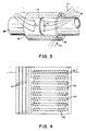
- Figure 1 is a schematic sectional view illustrative of the practice of the invention in the treatment of a welded joint in stainless steel piping as employed in nuclear power plants.
- Figure 2 is an idealized stress-strain diagram illustrative of the progressive stress modification in a welded pipe workpiece in response to the application of remotely generated radiant heat thereto the presence of cooling water flowing therethrough, followed by subsequent cooling.
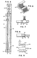
- Figure 3 is a schematic oblique view of the application of a radiant energy heating element to the weldment area of a stainless steel pipe in accord with the principles of this invention.
- Figure 4 is a sectional view, as taken on the line 3-3 of Figure 3 of a portion of a radiant heating module incorporating the principles of this invention.
- Figure 5 is a sectional view, as taken on the line 4-4 of Figure 4.
- Figures 6 through 8 are schematic oblique views of selectively shaped radiant heating modules adapted to accommodate varying workpiece surface contours.
- Figure 9 is a schematic diagram of a power control system for a heating assembly of the type described.
- the improved method and apparatus of this invention includes the in situ exposure of a weldment 10 and a zone on either side thereof, as indicated by the dotted line 12, at the juncture of two sections of stainless steel pipe 14 to externally generated heat 16 in an ovenlike atmosphere.
- externally generated heat 16 is initially essential of radiant character, generated by the passage of controlled amounts of electrical current through one or more selectively sized and/or shaped resistance heating wires 18 located in spaced relation to the external pipe and weld surfaces 20 concurrent with the passage of cool and fluid 30 past the interior pipe wall surface 32.
- an ovenlike housing Disposed in surrounding relation to the wires 18 is an ovenlike housing formed of an insulating shielding medium 22 desirably of ceramic and of radiant heat reflective character, to confine and redirect the generated heat, as indicated by the arrows 24, toward the pipe surface 20.
- the heat insulating and reflective shielding medium 22 is desirably backed up and supported by a rigid shell 26 having marginal side walls disposed in abutting relations with the pipe surface to complete the oven-like enclosure.
- the application of the externally generated heat to the external pipe surface within the zone 12, in conjunction with the continued flow of coolant fluid 30 through the pipe interior and adjacent the inner wall 32 thereof, serves to desirably develop a throughwall temperature differential gradient of appropriate character to develop sufficient thermally generated outer wall plastic deformation to create a stress greater than the materials compressive yield stress threat and a stress greater than the materials tensile yield stress at the inner wall surface thereof.
- a throughwall temperature differential gradient of appropriate character to develop sufficient thermally generated outer wall plastic deformation to create a stress greater than the materials compressive yield stress threat and a stress greater than the materials tensile yield stress at the inner wall surface thereof.
- Such phenomena is depicted in Figure 2 in idealized condition where the tensile and compressive yield strengths are represented by Tyt and Tyc respectively.
- the outer surface of the pipe is heated to establish a throughwall temperature differential of the appropriate magnitude to create a stress-strain distribution on the outer surface of the pipe that follows curve OA and a stress-strain distribution on the inner surface of the pipe that follows curve OB.
- the temperature differential is of such character to provide an outer wall temperature of a magnitude to create a localized thermal stress in excess of the pipe material's compressive yield stress on the outer surface and in excess of the material's tensile yield stress on the inner surface thereof as represented by the points A and B.
- the reduction of the tensile stress state and desirably the conversion thereof into a residual compressive stress state on the inner pipe surface in the vicinity of the welded joint renders such area more resistant to stress corrosion and/or corrosion fatigue and operates to reduce intergranular stress corrosion cracking at such location.
- FIG. 3-5 there is illustrated an assembled cylindrical shell type heating element assembly generally designated 36 and made up of, a plurality, is at least two segments 40 and 42 of a length sufficient to extend on either side of weld 44 in two sections of straight stainless steel pipe 46, 48.
- each of the partial cylindrical segments includes a plurality of elongate non-conducting ceramic support members 50 having resistance heating wires 52 coiled thereabout and terminally connected to bus bars 54 carrying, for example 480 volts of 3 phase A.C. power.
- the ceramic support members 50 are terminally supported and maintained in predetermined spaced relation with each other by shell insulators 56 and are backed by a radiant heat reflective wall 58, suitably also of high temperature ceramic material.
- the entire assembly of the bus bars 54, shell insulators 56 and reflective wall 58 are surrounded on three sides by a stainless steel housing 60.
- the shell insulators 56 are transversely dimensioned so as to position the resistance heating wires 52 in closely spaced by separated relation with the exterior surface of the pipe, as indicated by the dotted line 62 and to also serve as end walls in the oven-like enclosure.
- a plurality of thermocouples 70 are desirably mounted on the exterior surface of the pipe section 46 and 48 to provide a continuous flow of temperature information as to actual temperature at the pipe surface and thereby permit a ready control of heating rates.
- Power cables 72 serve to provide electrical power to the bus bar 54 and appropriate power rheostats, not shown, regulate the amount of power supplied thereto.
- FIGS. 6 through 8 schematically depict warming weld location geometries in piping sections and the ready adaptation of modular radiant heating assemblies thereto.
- Figure 6 for example schematically depicts a cylindically shaped heating assembly made up of three 120° sections 80.
- Figure 7 schematically depicts the mounting of an assembly of the type shown in Figure 6 over one of the weldments 82 interconnecting a straight pipe section 84 to a valve 86 in the general form of a "Tee" joint.
- Figure 8 shows a tapering heating assembly 90 mounted over a weld 92 intermediate a reducer transition pipe section 94 and a reduced diameter pipe section 96.
- one set of radiant heating elements will be disposed in parallel spaced relation with the surface of the reducer section 94 and a second set of heating elements will be disposed parallel to the surface of the pipe 96.
- FIG. 9 is a schematic depiction of a system for controlling the rate of heat application to the outer surface of the workpiece 110.
- the thermocouples 70 feed a continuous stream of temperature data, indicative of workpiece with surface temperature, to a comparator unit 100 which also continuously receives data, through sensor 102, of the coolant water temperature flowing past the inner surface of the workpiece.
- Such input data is compared with preprogrammed data values indicative of desired temperatures on a finite time base and the differences there between are utilized to provide a series of control signals 104 to a power control unit 106 for regulating the amount of power supplied to the radiant heating elements 52 from an external power source 108.
- the foregoing described modular form of construction can not only accommodate differing workpiece contours but also provides for the readily controlled application of heat to the workpiece and to portions thereof.
- the disclosed construction readily can accommodate metals having differing coefficents of thermal expansion and provide adequate, yet different throughwall temperature differentials in each alloy and/or appropriate temperature differentials longitudinally of the pipe adjacent to the weld area.
- radiant heating elements other than the heretofore described resistance wires could be employed for certain installations and areas of treatment as for example, high energy lamps employing quartz filaments or other high temperature ceramic or metal-ceramic mixtures as heating elements.
Landscapes
- Chemical & Material Sciences (AREA)
- Engineering & Computer Science (AREA)
- Physics & Mathematics (AREA)
- Thermal Sciences (AREA)
- Crystallography & Structural Chemistry (AREA)
- Mechanical Engineering (AREA)
- Materials Engineering (AREA)
- Metallurgy (AREA)
- Organic Chemistry (AREA)
- Heat Treatment Of Articles (AREA)
Applications Claiming Priority (1)
| Application Number | Priority Date | Filing Date | Title |
|---|---|---|---|
| US07/140,547 US4948435A (en) | 1988-01-04 | 1988-01-04 | Method for inhibiting stress corrosion cracking |
Publications (1)
| Publication Number | Publication Date |
|---|---|
| EP0452582A1 true EP0452582A1 (de) | 1991-10-23 |
Family
ID=22491744
Family Applications (1)
| Application Number | Title | Priority Date | Filing Date |
|---|---|---|---|
| EP90304303A Withdrawn EP0452582A1 (de) | 1988-01-04 | 1990-04-20 | Verfahren und Vorrichtung zur Verhinderung von Spannungsrisskorrosion |
Country Status (2)
| Country | Link |
|---|---|
| US (1) | US4948435A (de) |
| EP (1) | EP0452582A1 (de) |
Cited By (2)
| Publication number | Priority date | Publication date | Assignee | Title |
|---|---|---|---|---|
| US7114881B2 (en) | 2000-10-24 | 2006-10-03 | Saipem S.P.A. | Method and apparatus for welding pipes together |
| WO2008107660A1 (en) * | 2007-03-02 | 2008-09-12 | The Welding Institute | Method of relieving residual stress in a welded structure |
Families Citing this family (7)
| Publication number | Priority date | Publication date | Assignee | Title |
|---|---|---|---|---|
| JP2503077B2 (ja) * | 1989-07-05 | 1996-06-05 | 日本碍子株式会社 | 電気ヒ―タ及びそれを用いた加熱方法 |
| GB9017522D0 (en) * | 1990-08-09 | 1990-09-26 | British Telecomm | A device and a method for heating recoverable articles |
| US5553106A (en) * | 1994-06-15 | 1996-09-03 | Hitachi, Ltd. | Residual stress improving method for members in reactor pressure vessel |
| US7428902B2 (en) * | 2004-12-15 | 2008-09-30 | Newport Medical Instruments, Inc. | Humidifier system for artificial respiration |
| JP4448873B2 (ja) * | 2007-08-29 | 2010-04-14 | 日立Geニュークリア・エナジー株式会社 | 小口径配管の残留応力改善方法 |
| KR100909118B1 (ko) * | 2008-10-09 | 2009-07-23 | 한국항공대학교산학협력단 | 응력 부식균열 형성장치 |
| US20120217227A1 (en) * | 2011-02-28 | 2012-08-30 | General Electric Company | Method of introducing compressive stress in a welded joint |
Citations (4)
| Publication number | Priority date | Publication date | Assignee | Title |
|---|---|---|---|---|
| GB958019A (en) * | 1959-04-06 | 1964-05-13 | Thompson Ltd John | Improvements relating to the heating of welded structures for stress relief and other purposes |
| US3567907A (en) * | 1968-04-30 | 1971-03-02 | Babcock & Wilcox Co | Apparatus for heat treating a pressure vessel |
| US4229235A (en) * | 1977-10-25 | 1980-10-21 | Hitachi, Ltd. | Heat-treating method for pipes |
| US4349724A (en) * | 1980-11-07 | 1982-09-14 | Russell Ellersick | Articulate radiant heater module |
Family Cites Families (2)
| Publication number | Priority date | Publication date | Assignee | Title |
|---|---|---|---|---|
| US4188419A (en) * | 1971-02-12 | 1980-02-12 | Licentia Patent-Verwaltungs-G.M.B.H. | Method for preventing cracks below seams during plating and welding |
| JPS5950730B2 (ja) * | 1978-06-07 | 1984-12-10 | 第一高周波工業株式会社 | オ−ステナイト系ステンレス鋼管などの残留応力の改善方法 |
-
1988
- 1988-01-04 US US07/140,547 patent/US4948435A/en not_active Expired - Fee Related
-
1990
- 1990-04-20 EP EP90304303A patent/EP0452582A1/de not_active Withdrawn
Patent Citations (4)
| Publication number | Priority date | Publication date | Assignee | Title |
|---|---|---|---|---|
| GB958019A (en) * | 1959-04-06 | 1964-05-13 | Thompson Ltd John | Improvements relating to the heating of welded structures for stress relief and other purposes |
| US3567907A (en) * | 1968-04-30 | 1971-03-02 | Babcock & Wilcox Co | Apparatus for heat treating a pressure vessel |
| US4229235A (en) * | 1977-10-25 | 1980-10-21 | Hitachi, Ltd. | Heat-treating method for pipes |
| US4349724A (en) * | 1980-11-07 | 1982-09-14 | Russell Ellersick | Articulate radiant heater module |
Non-Patent Citations (1)
| Title |
|---|
| PATENT ABSTRACTS OF JAPAN, vol. 4, no. 173 (C-32)[655], 29th November 1980; & JP-A-55 110 729 (ISHIKAWAJIMA HARIMA) 26-08-1980 * |
Cited By (2)
| Publication number | Priority date | Publication date | Assignee | Title |
|---|---|---|---|---|
| US7114881B2 (en) | 2000-10-24 | 2006-10-03 | Saipem S.P.A. | Method and apparatus for welding pipes together |
| WO2008107660A1 (en) * | 2007-03-02 | 2008-09-12 | The Welding Institute | Method of relieving residual stress in a welded structure |
Also Published As
| Publication number | Publication date |
|---|---|
| US4948435A (en) | 1990-08-14 |
Similar Documents
| Publication | Publication Date | Title |
|---|---|---|
| US4447690A (en) | Inductive preheating of upset tubing | |
| US4229235A (en) | Heat-treating method for pipes | |
| CA2708509C (en) | Controlled electric induction heating of an electrically conductive workpiece in a solenoidal coil with flux compensators | |
| US4948435A (en) | Method for inhibiting stress corrosion cracking | |
| US3258573A (en) | Welding and forming method and apparatus | |
| IE67552B1 (en) | Method and apparatus for welding workpieces made of superalloys | |
| US4505763A (en) | Heat-treating method of weld portion of piping system and heating coil for the heat treatment | |
| WO2008107660A1 (en) | Method of relieving residual stress in a welded structure | |
| AU738294B2 (en) | High frequency induction fusing | |
| JPH0437145B2 (de) | ||
| US5018706A (en) | Apparatus for inhibiting stress corrosion cracking | |
| US4872926A (en) | Process for heat treating metals or metal alloys in a thermal plasma | |
| CA2015020A1 (en) | Method and apparatus for inhibiting stress corrosion cracking | |
| US4588869A (en) | Method for relieving residual stresses by controlling weld heat input | |
| JPH048986A (ja) | 溶接継手近傍の応力腐食を防ぐための方法と装置 | |
| EP2192017B1 (de) | Verfahren zum Geradebiegen und Kalibrieren eines Eisenbahndrehgestells mithilfe von magnetischer Induktionsheizung | |
| CN1055892A (zh) | 防止应力腐蚀裂纹的方法和设备 | |
| JPH11209825A (ja) | 溶接後熱処理装置 | |
| US4807801A (en) | Method of ameliorating the residual stresses in metallic duplex tubes and the like and apparatus therefor | |
| FI72749C (fi) | Anordning och foerfarande foer lokalgloedgning av roermaterial. | |
| Murakawa et al. | Mechanical Behavior in Local Postweld Heat Treatment | |
| EP0156545B1 (de) | Wärmebehandlungsverfahren mittels selbstregulierender Heizvorrichtung | |
| JP4625078B2 (ja) | ジルコニウム合金からなる燃料集合体を熱処理するための方法および装置 | |
| JPS5852428A (ja) | 軸の応力改善熱処理法 | |
| Korol ‘Kov | Special features of heat treatment of welded joints in stainless steel pipelines |
Legal Events
| Date | Code | Title | Description |
|---|---|---|---|
| PUAI | Public reference made under article 153(3) epc to a published international application that has entered the european phase |
Free format text: ORIGINAL CODE: 0009012 |
|
| AK | Designated contracting states |
Kind code of ref document: A1 Designated state(s): AT BE CH DE DK ES FR GB GR IT LI LU NL SE |
|
| 17P | Request for examination filed |
Effective date: 19920416 |
|
| STAA | Information on the status of an ep patent application or granted ep patent |
Free format text: STATUS: THE APPLICATION IS DEEMED TO BE WITHDRAWN |
|
| 18D | Application deemed to be withdrawn |
Effective date: 19931130 |