EP0452611B1 - Spritzgiessdüse mit einem hin- und hergehenden Heiztorpedo - Google Patents
Spritzgiessdüse mit einem hin- und hergehenden Heiztorpedo Download PDFInfo
- Publication number
- EP0452611B1 EP0452611B1 EP91100012A EP91100012A EP0452611B1 EP 0452611 B1 EP0452611 B1 EP 0452611B1 EP 91100012 A EP91100012 A EP 91100012A EP 91100012 A EP91100012 A EP 91100012A EP 0452611 B1 EP0452611 B1 EP 0452611B1
- Authority
- EP
- European Patent Office
- Prior art keywords
- mold
- gate
- channel
- mold cavity
- plastic
- Prior art date
- Legal status (The legal status is an assumption and is not a legal conclusion. Google has not performed a legal analysis and makes no representation as to the accuracy of the status listed.)
- Expired - Lifetime
Links
Images

Classifications
-
- B—PERFORMING OPERATIONS; TRANSPORTING
- B29—WORKING OF PLASTICS; WORKING OF SUBSTANCES IN A PLASTIC STATE IN GENERAL
- B29C—SHAPING OR JOINING OF PLASTICS; SHAPING OF MATERIAL IN A PLASTIC STATE, NOT OTHERWISE PROVIDED FOR; AFTER-TREATMENT OF THE SHAPED PRODUCTS, e.g. REPAIRING
- B29C45/00—Injection moulding, i.e. forcing the required volume of moulding material through a nozzle into a closed mould; Apparatus therefor
- B29C45/17—Component parts, details or accessories; Auxiliary operations
- B29C45/26—Moulds
- B29C45/27—Sprue channels ; Runner channels or runner nozzles
- B29C45/30—Flow control means disposed within the sprue channel, e.g. "torpedo" construction
-
- B—PERFORMING OPERATIONS; TRANSPORTING
- B29—WORKING OF PLASTICS; WORKING OF SUBSTANCES IN A PLASTIC STATE IN GENERAL
- B29C—SHAPING OR JOINING OF PLASTICS; SHAPING OF MATERIAL IN A PLASTIC STATE, NOT OTHERWISE PROVIDED FOR; AFTER-TREATMENT OF THE SHAPED PRODUCTS, e.g. REPAIRING
- B29C45/00—Injection moulding, i.e. forcing the required volume of moulding material through a nozzle into a closed mould; Apparatus therefor
- B29C45/17—Component parts, details or accessories; Auxiliary operations
- B29C45/26—Moulds
- B29C45/27—Sprue channels ; Runner channels or runner nozzles
- B29C45/30—Flow control means disposed within the sprue channel, e.g. "torpedo" construction
- B29C2045/306—Movable torpedoes
Definitions
- the present invention relates to a plastic molding system according to the first part of claim 1 and a method for delivering a melt stream of moldable plastic material under pressure through a flow passageway into a mold cavity.
- US-A-4 268 240 shows an air operated valve gate with a heated nozzle combined with a hot runner system for supplying resin to the mold cavity.
- the mold gate is opened or closed by moving a valve stem into opening or closing position with respect to the mold gate.
- Heated probes are also known.
- US-A 4 376 244 shows a fixed heated probe inside a channel combined with an insulated runner system for supplying a resin to the mold cavity.
- the gate remains in the open condition relying on ejection pressure to push out the frozen gate slug at the beginning of each injection cycle.
- the GB-A 2 202 787 shows a method of injection molding comprises feeding a synthetic resin through a gate into a cavity.
- the resin in the gate is cooled to solidification using a cooling medium in a passage is to close the gate after the cavity is filled with molten resin, thereby closing the gate.
- the solidified resin in the gate is melted by a heater to open a gate in readeness for the next injection molding operation.
- the disadvantage of the method is that the tip of the heater remains within the gate so that the flow channel in the gate is narrowed and the gate is not free of the heater during the injection procedure. Furthermore it needs more time for freezing of the molten plastic within the gate in case the heater remains within the area of the gate.
- the size of the gate orifice in combination with the proximity of the fixed heated probe thereto must be designed to both allow a quick freeze of resin in the gate area to shut off the gate and a large enough flow passage after the frozen resin is melted to allow easy filling when the gate is open. Naturally, also this must be done quickly and expeditiously in a rapid operating cycle. Too large a passage means little or even no freeze off at all, causing melted resin to drool from the mold gate. Too small a passage means restricted resin flow through the gate area causing the resin to be shear heated and often causes resin degradation during filling. Indeed, in some cases fixed heated probes cannot be used when processing heat sensitive resins.
- a heated probe is provided in the mold channel and means are connected with the heated probe for moving said heated probe from a first position spaced from the gate to provide a wide flow channel in the mold gate to a second position adjacent the mold gate to melt the frozen plastic in the gate.
- the mold channel generally comprises a heated nozzle and heating means are generally provided in the distribution plate to maintain the plastic in the molten condition in the distribution channel. Cooling means are generally provided adjacent the gate to cool the gate area.
- the present invention provides a method for delivering a melt stream of moldable plastic material under pressure through a flow passageway into a mold cavity.
- the method comprises: conveying a plastic melt through a distribution channel and through a mold channel communicating with the distribution channel to a mold cavity via a mold gate between the mold channel and the mold cavity to fill the mold cavity; freezing the plastic melt in the gate after the mold cavity is filled to block access from the mold channel to the mold cavity; providing a heated probe in the mold channel spaced from the gate; moving the heated probe to a position adjacent the gate to melt the frozen plastic and open the gate; and moving the heated probe into a position spaced from the gate to provide a wide flow channel to the mold cavity.
- the method of the present invention includes the step of feeding the plastic melt to the mold cavity via a heated nozzle and also includes the step of heating the plastic in the distribution channel.
- the gate area may be cooled to freeze the plastic in the gate after the mold cavity is filled.
- the method and apparatus of the present invention are readily usable in a rapid multicavity system.
- the present invention conveniently opens and closes the gate area in a synchronized manner in the multicavity system.
- the movement of the probe may be controlled by either a hydraulic piston which is more space efficient or an air piston which has less risk of fire.
- the present invention is readily usable with heat sensitive resins.
- the large flow passage provided in accordance with the present invention avoids excessive shear heating and the movement of the probe efficiently opens the gate area by melting the frozen plastic in the gate.
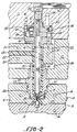
- Figures 1 and 2 show a representative embodiment of the present invention, with Figure 1 showing the gate open and the heated probe retracted and Figure 2 showing the gate closed and the probe in the forward position adjacent the mold gate.
- Figure 1 shows the gate open and the heated probe retracted
- Figure 2 shows the gate closed and the probe in the forward position adjacent the mold gate.
- a single mold cavity has been shown; however, it should be understood that the apparatus and method of the present invention is particularly suitable for multicavity molds wherein the system shown in Figures 1 and 2 would be duplicated for each mold.
- stationary mold plate 10 is separated from manifold plate 11 by an intermediate or backing plate 12.
- Mold plate 10 together with coacting movable mold plate l3 defines a plurality of mold cavities 14, with only one shown in the drawings.
- the mold cavities 14 are accessible through mold gate 15.
- Cooling channel 16 may be provided in the mold plates.
- Hot runner manifold or distributing plate 20 including manifold heating means 21 supplied by an appropriate heating source (not shown) contains transverse manifold channel or distribution channel 22 which is fed with the desired molten plastic 23 from an appropriate source of molten plastic (not shown) for delivering the molten plastic under pressure.
- Manifold channel 22 communicates with and feeds molten plastic 23 to axial mold channel 24 in nozzle 25 which may be heated if desired and which in turn feeds the molten plastic to mold 14 via gate 15.
- Hot runner manifold 20 is bracketed by manifold plate 11 and backing plate 12 but separated therefrom by an air gap 26. Seals 27 are provided between nozzle 25 and mold plate 10 and cooling channels 28 are provided between the nozzle 25 and mold plate 10.
- Heated probe 30 is provided which may comprise a steel rod 31 having a shaped, pointed rod tip 32 and containing a central heated core 33 to which current is admitted by cables 34 from an appropriate power source (not shown).
- Means 35 are provided for moving the heated probe 30 from a first position shown in Figure 1 spaced from mold gate 15 to provide a wide flow channel in the mold gate to a second position shown in Figure 2 adjacent mold gate 15.
- Any desired means may be provided for moving the mold probe, as for example a hydraulic piston which is more space efficient or an air piston which has less risk of fire.
- the particular embodiment shown in Figures 1 and 2 uses an air piston which will be described below.
- the heated probe 30 is guided in cylinder 40, boss 41 and nozzle 25. Sealing ring 42 is provided contacting the wall of a bore of boss 41 in which probe 30 is slidable to minimize leakage along the surface of the probe.
- the end of probe 30 opposite gate 15 is received in cylinder 40 with rod head 43 affixed to piston 44 and movable in cylinder chamber 45 together with piston 44.
- Lower cylinder chamber wall 46 limits the downward stroke of probe 30 and upper cylinder chamber wall 47 limits the upward stroke of probe 30.
- Air is admitted to cylinder chamber 45 via air passages 48 and 49, with air passage 48 feeding air to the upper surface of piston 44 to cause downward movement and air passage 49 feeding air to the lower surface of piston 44 to cause upward movement, all in a known manner.
- molten plastic 23 is fed to mold cavity 14 via manifold channel 22, mold channel 24 and gate 15 to fill the mold cavity.
- Probe 30 is spaced from the gate as shown in Figure 1 to provide a wide flow path through the mold gate. After the mold cavity is filled, flow thereto ceases and the molten resin in the mold gate freezes. Cooling channels 28 adjacent the mold gate 15 promote rapid freezing of the plastic in the gate area. The frozen plastic in the gate area blocks further access to the mold cavity and permits removal of the molded article by opening movable mold plate 13 in a manner known to the art.
- probe 30 is moved from its first position spaced from the gate as shown in Figure 1 to its second position adjacent the mold gate as shown in Figure 2 by the appropriate means for moving the probe, as the air piston shown in Figures 1 and 2.
- the heated probe melts the frozen plastic in the gate area, especially with the action of probe tip 32, whereupon the probe is retracted from the position shown in Figure 2 to the position shown in Figure 1 to provide a wide gate area for refilling the mold cavity.
- the process and apparatus of the present invention overcomes the difficulties obtained heretofore.
- the present invention is particularly suitable for processing heat sensitive resins in both insulated or hot runner applications.
- a large flow passage is provided to avoid excessive shear heating and the frozen gate is ready and conveniently opened by melting it with the advancing probe, especially using the spaced pointed rod tip.
- the present invention is particularly suitable for multicavity molding.
Landscapes
- Engineering & Computer Science (AREA)
- Manufacturing & Machinery (AREA)
- Mechanical Engineering (AREA)
- Moulds For Moulding Plastics Or The Like (AREA)
- Injection Moulding Of Plastics Or The Like (AREA)
- Fish Paste Products (AREA)
- Surgical Instruments (AREA)
Claims (5)
- Kunststofformsystem zum Führen eines Schmelzestroms aus formbarem Kunststoffmaterial unter Druck durch einen Fliesskanal und in einen Formraum (14) mit einer Verteilerplatte (20), welche einen Verteilerkanal (22) zum Führen einer Kunststoffschmelze (23) beinhaltet, einer Düse (25) mit einem Formkanal (24) darin, der in Verbindung mit dem Verteilerkanal (22) steht, einem Formraum (14), der mit dem Formkanal (24) in Verbindung steht, einem Formeinlauf (15) zwischen dem Formraum (14) und dem Formkanal (24), wobei aufgeschmolzener Kunststoff (23) von dem Verteilerkanal (22) durch den Formkanal (24) und den Einlauf (15) fliesst, um den Formraum (14) aufzufüllen, und in dem Einlauf (15) erstarrt, wenn der Formraum (14) gefüllt ist,
dadurch gekennzeichnet,
dass in dem Formkanal (24) ein Heiztorpedo (30) angeordnet ist, und dass mit dem Heiztorpedo (30) eine Einrichtung zum Bewegen des Heiztorpedos (30) von einer ersten Position entfernt von dem Einlauf (15) zum Erreichen eines weiten Fliesskanals in den Formeinlauf (15) in eine zweite Position nahe dem Formeinlauf (15) zum Aufschmelzen des erstarrten Kunststoff in dem Einlauf (15) verbunden ist. - System nach Anspruch 1, dadurch gekennzeichnet, dass das Torpedo (30) eine zugespitzte Stangenpitze (32) aufweist.
- Verfahren zum Führen eines Schmelzestromes aus formbarem Kunststoffmaterial unter Druck durch einen Fliesskanal in einen Formraum (14), wobei Kunststoffschmelze (23) durch einen Verteilerkanal (22) und durch einen Formkanal (24), der mit dem Verteilerkanal (22) in Verbindung steht, zu einem Formraum (14) über einen Formeinlauf (15) zwischen dem Formkanal (24) und dem Formraum (14) geführt wird, um den Formraum (14) aufzufüllen, wobei die Kunststoffschmelze in dem Einlauf (15) nach dem Auffüllen des Formraumes (14) erstarrt, um einen Zugang von dem Formkanal (24) zu dem Formraum (14) zu blockieren, dadurch gekennzeichnet, dass ein Heiztorpedo (30) in dem Formkanal (24) fern von dem Einlauf (15) in eine Position nahe dem Einlauf (15) bewegt wird, um den erstarrten Kunststoff aufzuschmelzen und den Einlauf (15) zu öffnen, und in eine Position fern von dem Einlauf (15) zurückbewegt wird, um einen weiten Fliesskanal zu dem Formraum (14) zu gewährleisten.
- Verfahren nach Anspruch 3, dadurch gekennzeichnet, dass der Kunststoff in dem Verteilerkanal (22) erwärmt wird.
- Verfahren nach Anspruch 3 oder 4, dadurch gekennzeichnet, dass der Einlauf (15) gekühlt wird, um den Kunststoff in dem Einlauf (15), nachdem der Formraum (14) gefüllt worden ist, erstarren zu lassen.
Priority Applications (1)
| Application Number | Priority Date | Filing Date | Title |
|---|---|---|---|
| AT91100012T ATE100371T1 (de) | 1990-04-16 | 1991-01-02 | Spritzgiessduese mit einem hin- und hergehenden heiztorpedo. |
Applications Claiming Priority (2)
| Application Number | Priority Date | Filing Date | Title |
|---|---|---|---|
| US07/509,148 US5037598A (en) | 1990-04-16 | 1990-04-16 | Reciprocating heated nozzle |
| US509148 | 1990-04-16 |
Publications (3)
| Publication Number | Publication Date |
|---|---|
| EP0452611A2 EP0452611A2 (de) | 1991-10-23 |
| EP0452611A3 EP0452611A3 (en) | 1992-03-18 |
| EP0452611B1 true EP0452611B1 (de) | 1994-01-19 |
Family
ID=24025488
Family Applications (1)
| Application Number | Title | Priority Date | Filing Date |
|---|---|---|---|
| EP91100012A Expired - Lifetime EP0452611B1 (de) | 1990-04-16 | 1991-01-02 | Spritzgiessdüse mit einem hin- und hergehenden Heiztorpedo |
Country Status (5)
| Country | Link |
|---|---|
| US (1) | US5037598A (de) |
| EP (1) | EP0452611B1 (de) |
| JP (1) | JPH06166063A (de) |
| AT (1) | ATE100371T1 (de) |
| DE (1) | DE69101018T2 (de) |
Families Citing this family (14)
| Publication number | Priority date | Publication date | Assignee | Title |
|---|---|---|---|---|
| FR2681813A1 (fr) * | 1991-09-26 | 1993-04-02 | Mecaplast Sa | Element de buse d'injection pour moule. |
| CA2099334C (en) * | 1993-06-25 | 2001-09-11 | Jobst Ulrich Gellert | Injection molding insert with melt inlet and pin aligned |
| SE506586C2 (sv) * | 1996-05-13 | 1998-01-19 | Flexiject Innovations Hb | Formsprutning av detaljer av olika vikt, storlek och form i en och samma processcykel |
| IT1294475B1 (it) * | 1997-06-19 | 1999-04-12 | Acrilux Spa | Ugello di iniezione con torpedo scorrevole. |
| US5945139A (en) * | 1997-06-30 | 1999-08-31 | Siemens Energy & Automation, Inc. | Injection mold live runner apparatus |
| DE19846710B4 (de) * | 1998-10-09 | 2007-08-16 | Vereinigung zur Förderung des Instituts für Kunststoffverarbeitung in Industrie und Handwerk an der Rhein.-Westf. Technischen Hochschule Aachen eV | Verfahren zum Spritzgießen von Mikroformteilen aus thermoplastischen Kunststoffen mit einer geringen Angussmasse |
| US6328554B1 (en) | 1999-07-07 | 2001-12-11 | Husky Injection Molding System, Ltd. | Valve gating arrangement for an insulated runner |
| US6450798B1 (en) | 2000-02-04 | 2002-09-17 | Avaya Technology Corp. | Apparatus for multiple cavity injection molding |
| DE102005049605A1 (de) * | 2004-10-19 | 2006-04-20 | Mold-Masters Ltd., Georgetown | Verteilereinsatz für eine Spritzgießvorrichtung |
| US7341688B2 (en) * | 2004-11-19 | 2008-03-11 | Husky Injection Molding Systems Ltd. | Valve gate for a hot runner injection molding machine |
| CN102653123B (zh) * | 2012-05-07 | 2014-04-09 | 常州工学院 | 凝料自动推出的点浇口注塑模 |
| DE102012104291B4 (de) * | 2012-05-16 | 2014-07-10 | Günther Heisskanaltechnik Gmbh | Düsenmundstück für eine Spritzgießdüse, Spritzgießdüse und Spritzgießwerkzeug |
| CA3008635A1 (en) | 2015-12-16 | 2017-06-22 | Jonathan Edward Meegan | Resin infusion process for manufacturing fiber-reinforced composites |
| TWI652160B (zh) | 2018-01-19 | 2019-03-01 | 新巨企業股份有限公司 | Feed nozzle for low pressure injection molding |
Family Cites Families (9)
| Publication number | Priority date | Publication date | Assignee | Title |
|---|---|---|---|---|
| US3758248A (en) * | 1972-12-20 | 1973-09-11 | H Drazick | Injection plastic feeder |
| JPS5372063A (en) * | 1976-12-09 | 1978-06-27 | Asahi Chemical Ind | Hottrunner mold |
| US4268240A (en) * | 1978-01-06 | 1981-05-19 | Husky Injection Molding Systems | Actuating mechanism for gate valve of injection nozzle |
| JPS5874332A (ja) * | 1981-10-30 | 1983-05-04 | Sei Tsutsumi | 合成樹脂射出成形方法およびその装置 |
| JPS59143624A (ja) * | 1983-02-05 | 1984-08-17 | Shoichi Teraoka | ホツトランナ−・ノズルのゲ−ト開閉栓 |
| CA1230459A (en) * | 1985-04-30 | 1987-12-22 | Gellert, Jobst Ulrich | Valve gated probe |
| JPS63236615A (ja) * | 1987-03-26 | 1988-10-03 | Sanri Kk | 間欠冷却方式によるランナ−レス合成樹脂射出成形方法およびその装置 |
| JPS6487319A (en) * | 1987-09-30 | 1989-03-31 | Nissei Plastics Ind Co | Method for controlling temperature of injection molder |
| CA1261575A (en) * | 1988-04-13 | 1989-09-26 | Jobst U. Gellert | Injection molding valve gating one of two nozzles in tandem |
-
1990
- 1990-04-16 US US07/509,148 patent/US5037598A/en not_active Expired - Lifetime
-
1991
- 1991-01-02 AT AT91100012T patent/ATE100371T1/de not_active IP Right Cessation
- 1991-01-02 DE DE91100012T patent/DE69101018T2/de not_active Expired - Fee Related
- 1991-01-02 EP EP91100012A patent/EP0452611B1/de not_active Expired - Lifetime
- 1991-04-16 JP JP3110976A patent/JPH06166063A/ja active Pending
Also Published As
| Publication number | Publication date |
|---|---|
| DE69101018D1 (de) | 1994-03-03 |
| DE69101018T2 (de) | 1994-05-05 |
| JPH06166063A (ja) | 1994-06-14 |
| US5037598A (en) | 1991-08-06 |
| EP0452611A3 (en) | 1992-03-18 |
| EP0452611A2 (de) | 1991-10-23 |
| ATE100371T1 (de) | 1994-02-15 |
Similar Documents
| Publication | Publication Date | Title |
|---|---|---|
| US4530654A (en) | Injection molding peripheral opening core ring gate | |
| US4521179A (en) | Injection molding core ring gate system | |
| US5037598A (en) | Reciprocating heated nozzle | |
| US7198740B2 (en) | Lateral gating injection molding apparatus | |
| EP1406754B1 (de) | Vorrichtung zum spritzgiessen von kunstoffgegenständen | |
| EP0385175B1 (de) | Spritzgusseinrichtung mit Gasdurchfluss durch die Ventilöffnung | |
| US6355197B1 (en) | Process and apparatus for forming plastic articles | |
| EP0873841B1 (de) | Spritzgiessdüse mit einteiligem Einspritzöffnungseinsatz zum Halten eines zylindrischen Ventils | |
| EP0916470B1 (de) | Spritzgiessvorrichtung mit seitlichem Anschnitt mit betätigtem Verteiler | |
| US4712995A (en) | Replaceable rocker arm assembly for injection molding system | |
| CA1085125A (en) | Injection molding machine and method | |
| US5387099A (en) | Injection molding valve member sealing bushing with a thin collar portion | |
| EP0475243B1 (de) | Etagenform mit isoliertem Einspritzkanal | |
| US2828509A (en) | Plastic molding machines | |
| US5423672A (en) | Molding device having a ring-gating and hole forming valve gate pin | |
| JPS606218B2 (ja) | プラスチック注入鋳型ダイ組立体 | |
| KR100445948B1 (ko) | 인젝션 노즐 및 인젝션 성형 방법 | |
| US5219593A (en) | Injection molding apparatus | |
| US5460508A (en) | Resin molding method and apparatus | |
| CA1168008A (en) | Hot sprue assembly for an injection molding machine | |
| NZ526988A (en) | Metering device for a plastics moulding machine | |
| EP0106980A1 (de) | Verschlussdüse zum Spritzgiessen | |
| US20060159798A1 (en) | Method for producing mould parts by injection and plugged needle nozzle for an injection mould | |
| US5480606A (en) | Method and apparatus for reverse gated compression molding of thermoplastic material | |
| WO2002036323A1 (en) | Co-injection valve-gate bushing with separate material flow paths |
Legal Events
| Date | Code | Title | Description |
|---|---|---|---|
| PUAI | Public reference made under article 153(3) epc to a published international application that has entered the european phase |
Free format text: ORIGINAL CODE: 0009012 |
|
| AK | Designated contracting states |
Kind code of ref document: A2 Designated state(s): AT BE CH DE DK ES FR GB GR IT LI LU NL SE |
|
| PUAL | Search report despatched |
Free format text: ORIGINAL CODE: 0009013 |
|
| AK | Designated contracting states |
Kind code of ref document: A3 Designated state(s): AT BE CH DE DK ES FR GB GR IT LI LU NL SE |
|
| 17P | Request for examination filed |
Effective date: 19920316 |
|
| 17Q | First examination report despatched |
Effective date: 19920818 |
|
| GRAA | (expected) grant |
Free format text: ORIGINAL CODE: 0009210 |
|
| AK | Designated contracting states |
Kind code of ref document: B1 Designated state(s): AT BE CH DE DK ES FR GB GR IT LI LU NL SE |
|
| PG25 | Lapsed in a contracting state [announced via postgrant information from national office to epo] |
Ref country code: IT Free format text: LAPSE BECAUSE OF FAILURE TO SUBMIT A TRANSLATION OF THE DESCRIPTION OR TO PAY THE FEE WITHIN THE PRE;WARNING: LAPSES OF ITALIAN PATENTS WITH EFFECTIVE DATE BEFORE 2007 MAY HAVE OCCURRED AT ANY TIME BEFORE 2007. THE CORRECT EFFECTIVE DATE MAY BE DIFFERENT FROM THE ONE RECORDED.SCRIBED TIME-LIMIT Effective date: 19940119 Ref country code: DK Effective date: 19940119 Ref country code: NL Effective date: 19940119 Ref country code: SE Effective date: 19940119 Ref country code: AT Effective date: 19940119 Ref country code: GR Free format text: LAPSE BECAUSE OF FAILURE TO SUBMIT A TRANSLATION OF THE DESCRIPTION OR TO PAY THE FEE WITHIN THE PRESCRIBED TIME-LIMIT Effective date: 19940119 Ref country code: ES Free format text: THE PATENT HAS BEEN ANNULLED BY A DECISION OF A NATIONAL AUTHORITY Effective date: 19940119 Ref country code: BE Effective date: 19940119 Ref country code: CH Effective date: 19940119 Ref country code: FR Effective date: 19940119 Ref country code: LI Effective date: 19940119 |
|
| REF | Corresponds to: |
Ref document number: 100371 Country of ref document: AT Date of ref document: 19940215 Kind code of ref document: T |
|
| REF | Corresponds to: |
Ref document number: 69101018 Country of ref document: DE Date of ref document: 19940303 |
|
| REG | Reference to a national code |
Ref country code: CH Ref legal event code: PL |
|
| EN | Fr: translation not filed | ||
| NLV1 | Nl: lapsed or annulled due to failure to fulfill the requirements of art. 29p and 29m of the patents act | ||
| PLBE | No opposition filed within time limit |
Free format text: ORIGINAL CODE: 0009261 |
|
| STAA | Information on the status of an ep patent application or granted ep patent |
Free format text: STATUS: NO OPPOSITION FILED WITHIN TIME LIMIT |
|
| PG25 | Lapsed in a contracting state [announced via postgrant information from national office to epo] |
Ref country code: GB Effective date: 19950102 |
|
| 26N | No opposition filed | ||
| PGFP | Annual fee paid to national office [announced via postgrant information from national office to epo] |
Ref country code: DE Payment date: 19950118 Year of fee payment: 5 |
|
| PG25 | Lapsed in a contracting state [announced via postgrant information from national office to epo] |
Ref country code: LU Free format text: LAPSE BECAUSE OF NON-PAYMENT OF DUE FEES Effective date: 19950131 |
|
| GBPC | Gb: european patent ceased through non-payment of renewal fee |
Effective date: 19950102 |
|
| PG25 | Lapsed in a contracting state [announced via postgrant information from national office to epo] |
Ref country code: DE Effective date: 19961001 |