EP0452733B1 - Herzschrittmacher mit veränderbarer Stimulationsrate und mit einer Schaltung zur Verarbeitung von mehrfachen Sensor- eingängen - Google Patents
Herzschrittmacher mit veränderbarer Stimulationsrate und mit einer Schaltung zur Verarbeitung von mehrfachen Sensor- eingängen Download PDFInfo
- Publication number
- EP0452733B1 EP0452733B1 EP91105271A EP91105271A EP0452733B1 EP 0452733 B1 EP0452733 B1 EP 0452733B1 EP 91105271 A EP91105271 A EP 91105271A EP 91105271 A EP91105271 A EP 91105271A EP 0452733 B1 EP0452733 B1 EP 0452733B1
- Authority
- EP
- European Patent Office
- Prior art keywords
- rate
- sensor
- signal
- matrix
- switch matrix
- Prior art date
- Legal status (The legal status is an assumption and is not a legal conclusion. Google has not performed a legal analysis and makes no representation as to the accuracy of the status listed.)
- Revoked
Links
- 238000012545 processing Methods 0.000 title claims description 29
- 239000011159 matrix material Substances 0.000 claims description 217
- 230000000694 effects Effects 0.000 claims description 80
- 230000015654 memory Effects 0.000 claims description 33
- 230000004044 response Effects 0.000 claims description 29
- 238000006243 chemical reaction Methods 0.000 claims description 22
- 239000008280 blood Substances 0.000 claims description 20
- 210000004369 blood Anatomy 0.000 claims description 20
- 238000011084 recovery Methods 0.000 claims description 17
- 230000000241 respiratory effect Effects 0.000 claims description 16
- 230000000638 stimulation Effects 0.000 claims description 13
- QVGXLLKOCUKJST-UHFFFAOYSA-N atomic oxygen Chemical compound [O] QVGXLLKOCUKJST-UHFFFAOYSA-N 0.000 claims description 9
- 229910052760 oxygen Inorganic materials 0.000 claims description 9
- 239000001301 oxygen Substances 0.000 claims description 9
- 238000001914 filtration Methods 0.000 claims description 3
- 230000036961 partial effect Effects 0.000 claims description 3
- 230000029058 respiratory gaseous exchange Effects 0.000 claims description 2
- 230000004936 stimulating effect Effects 0.000 claims 1
- 230000008859 change Effects 0.000 description 20
- 230000006870 function Effects 0.000 description 13
- 238000000034 method Methods 0.000 description 11
- 238000011217 control strategy Methods 0.000 description 8
- 230000000747 cardiac effect Effects 0.000 description 6
- 102100026827 Protein associated with UVRAG as autophagy enhancer Human genes 0.000 description 5
- 101710102978 Protein associated with UVRAG as autophagy enhancer Proteins 0.000 description 5
- 230000002503 metabolic effect Effects 0.000 description 5
- 230000008569 process Effects 0.000 description 5
- 230000002035 prolonged effect Effects 0.000 description 5
- 238000010586 diagram Methods 0.000 description 4
- 239000013078 crystal Substances 0.000 description 3
- 230000006461 physiological response Effects 0.000 description 3
- 238000012935 Averaging Methods 0.000 description 2
- 238000013459 approach Methods 0.000 description 2
- 230000036760 body temperature Effects 0.000 description 2
- 230000001419 dependent effect Effects 0.000 description 2
- 238000012544 monitoring process Methods 0.000 description 2
- 230000037081 physical activity Effects 0.000 description 2
- 238000012546 transfer Methods 0.000 description 2
- 230000009471 action Effects 0.000 description 1
- 230000003321 amplification Effects 0.000 description 1
- 230000036772 blood pressure Effects 0.000 description 1
- 238000010276 construction Methods 0.000 description 1
- 230000009977 dual effect Effects 0.000 description 1
- 238000005516 engineering process Methods 0.000 description 1
- 210000002837 heart atrium Anatomy 0.000 description 1
- 230000010247 heart contraction Effects 0.000 description 1
- 230000006872 improvement Effects 0.000 description 1
- 230000002452 interceptive effect Effects 0.000 description 1
- 230000003278 mimic effect Effects 0.000 description 1
- 230000005405 multipole Effects 0.000 description 1
- 238000003199 nucleic acid amplification method Methods 0.000 description 1
- 230000002062 proliferating effect Effects 0.000 description 1
- 230000000644 propagated effect Effects 0.000 description 1
- 230000002829 reductive effect Effects 0.000 description 1
- 230000008672 reprogramming Effects 0.000 description 1
- 230000036387 respiratory rate Effects 0.000 description 1
- 230000024977 response to activity Effects 0.000 description 1
- 230000000717 retained effect Effects 0.000 description 1
- 239000004065 semiconductor Substances 0.000 description 1
- 210000001013 sinoatrial node Anatomy 0.000 description 1
- 239000000126 substance Substances 0.000 description 1
- 230000036962 time dependent Effects 0.000 description 1
Images


Classifications
-
- A—HUMAN NECESSITIES
- A61—MEDICAL OR VETERINARY SCIENCE; HYGIENE
- A61N—ELECTROTHERAPY; MAGNETOTHERAPY; RADIATION THERAPY; ULTRASOUND THERAPY
- A61N1/00—Electrotherapy; Circuits therefor
- A61N1/18—Applying electric currents by contact electrodes
- A61N1/32—Applying electric currents by contact electrodes alternating or intermittent currents
- A61N1/36—Applying electric currents by contact electrodes alternating or intermittent currents for stimulation
- A61N1/362—Heart stimulators
- A61N1/37—Monitoring; Protecting
- A61N1/3702—Physiological parameters
- A61N1/3704—Circuits specially adapted therefor, e.g. for sensitivity control
-
- A—HUMAN NECESSITIES
- A61—MEDICAL OR VETERINARY SCIENCE; HYGIENE
- A61N—ELECTROTHERAPY; MAGNETOTHERAPY; RADIATION THERAPY; ULTRASOUND THERAPY
- A61N1/00—Electrotherapy; Circuits therefor
- A61N1/18—Applying electric currents by contact electrodes
- A61N1/32—Applying electric currents by contact electrodes alternating or intermittent currents
- A61N1/36—Applying electric currents by contact electrodes alternating or intermittent currents for stimulation
- A61N1/362—Heart stimulators
- A61N1/365—Heart stimulators controlled by a physiological parameter, e.g. heart potential
- A61N1/36585—Heart stimulators controlled by a physiological parameter, e.g. heart potential controlled by two or more physical parameters
Definitions
- the present invention relates generally to rate-responsive cardiac pacemakers, and more particularly to an implantable rate-responsive pacemaker wherein two or more sensors indicative of physiological demand are utilized in a fashion designed to realize the advantages of both sensors in a circuit producing a rate command signal which is used to operate the pacemaker at an optimum pacing rate which will closely match physiological need of the patient.
- a pacemaker is an implantable medical device which delivers electrical stimulation pulses to a patient's heart in order to keep the heart beating at a desired rate.
- Early pacemakers provided stimulation pulses at a fixed rate or frequency, such as 70 pulses per minute (ppm), thereby maintaining the heart beat at that fixed rate.
- pacemakers were designed to not only stimulate the heart, but also to monitor the heart. If a natural heart beat was detected within a prescribed time period (usually referred to as the "escape interval"), no stimulation pulse was delivered, thereby allowing the heart to beat on its own without consuming the limited power of the pacemaker or interfering with the normal operation of the heart.
- Such pacemakers are referred to as “demand pacemakers" because stimulation pulses are provided only as demanded by the heart.
- the base rate was programmably selectable, and thereafter became commonly known as the "programmed rate.” If the heart was able to beat on its own at a rate exceeding the base (or programmed) rate, then no stimulation pulses were provided. However, if the heart was not able to beat on its own at a rate exceeding the base rate, then stimulation pulses were provided to ensure that the heart would always beat at least at the base (or programmed) rate. Such operation was achieved by simply monitoring the heart for a natural beat during the escape interval. If natural activity was sensed, the timer which defined the escape interval was reset. If no natural activity was sensed, a stimulation pulse was provided as soon as the escape interval had timed out. Changing the base (or programmed) rate was accomplished by simply changing the duration of the escape interval.
- rate-responsive pacemakers have been developed which automatically change the rate at which the pacemaker provides stimulation pulses as a function of a sensed physiological parameter.
- the physiological parameter provides some indication of whether the heart should beat faster or slower, depending upon the physiological needs of the pacemaker user.
- the rate-responsive pacemaker maintains the "base rate" at a normal value, such as 60 pulses per minute (ppm).
- the heart is not able to beat faster on its own, so the pacemaker must assist. In order to do this effectively, the physiological need for the heart to beat faster must first be sensed, and the "base rate" of the rate-responsive pacer must be adjusted accordingly.
- rate-responsive pacemakers are known in the art which increase and decrease the "base rate” as a function of sensed physiological need.
- pacing rate refers to the rate at which the pacer provides stimulation pulses, or in the case of demand pacers, the rate at which the pacer would provide stimulation pulses in the absence of naturally occurring heart beats.
- an activity sensor which senses the physical activity level of the patient. See, for example, U.S. Patent No. 4,140,132, to Dahl, and U.S. Patent No. 4,485,813, to Anderson et al.
- a piezoelectric crystal is used as an activity sensor. Such a crystal generates an electrical signal when subjected to physical movement and stress according to well known principles. The electrical signal generated by the crystal may be processed and used to vary the pacing rate.
- sensors used in prior art rate-responsive pacers include sensors that sense respiration rate, respiratory minute volume, blood oxygen level, blood and/or body temperature, blood pressure, the length of the Q-T interval, the length of the P-R interval, etc. All of the sensors which may be used in rate-responsive pacers have particular advantages and disadvantages.
- the next generation of rate-responsive pacemakers uses two or more sensors simultaneously to control the pacing rate. It will be appreciated by those skilled in the art that the combination of signals from two or more sensors to be used to control pacing rate is a difficult and complex task. In the pacemaker of EP-A-0 225 839 the signals are in substance summarized.
- the goal of a system using two or more sensors should be to utilize the best properties of each of the sensors, while eliminating or minimizing their drawbacks.
- an activity sensor will react very quickly to the onset of exercise, closely mimicking the response of the sinus node in a healthy heart.
- an activity sensor does not measure any true physiological variable of the body, and as such may be a poor predictor of work level and of the optimum heart rate.
- a sensor measuring respiratory minute volume or venous blood temperature will provide a very good correlation to the level of exercise at higher levels of exercise.
- the sensor response of a respiratory minute volume sensor or venous blood temperature sensor is much slower than the response of the SA node, typically of the order of sixty to ninety seconds.
- a combination of an activity sensor and a respiratory minute volume sensor or venous blood temperature sensor could be used to control pacing rate in a manner which is more physiologic than either of the sensors separately.
- the combination technique may, however, prove quite complex in its implementation. For example, a summation and averaging of the two signals would not be optimum for the following reasons. At the onset of exercise, the activity sensor would deliver a signal, while the other sensor would not yet have reacted. Thus, the onset of heart activity would be slower than in the case of using activity alone.
- the good sensor response of the respiratory minute volume or blood temperature sensor would be averaged with the poorer response of the activity sensor. In this case, the result would not be as accurate as using the respiratory minute volume or blood temperature sensor alone.
- the activity sensor may be as good as the respiratory minute volume or blood temperature sensor because the latter two are inaccurate at low levels of exercise.
- the poor response of the activity sensor would be averaged with the good response of the respiratory minute volume or blood temperature sensor. Thus, the result again would not be as accurate as using the respiratory minute volume or blood temperature sensor alone.
- Another possible technique which may be used to combine the inputs from two sensors would be to take the highest value of the two sensors. This would in at least some cases yield a better result than the averaging technique discussed above. This combination would not, however, eliminate the erroneous increase in pacing rate resulting from external vibration picked up by the activity sensor.
- a rate-responsive pacemaker comprising conventional pulse generating means, one physiological sensor means, and an addressable rate matrix.
- the output of the rate matrix corresponds to the values of the sensor means and a selected operating mode of the pacer.
- the control strategy must be of a complexity sufficient to provide as an output a highly flexible sensor-indicated rate signal which will accurately follow a control strategy paralleling the physiological response of a healthy heart.
- two or more sensors are used to supply inputs to circuitry which will extract relevant information from each sensor and combine these signals in an optimum way so as to produce a signal which controls the rate of the pulse generator output.
- This circuitry is hereafter called a rate-response processor.
- two sensors are used, with one of them being an activity sensor (which responds quickly) and the other being a more physiologically responsive (but slower responding) sensor such as a blood temperature sensor or a respiratory minute volume sensor.
- sensors which could be used include a blood oxygen sensor (either blood oxygen saturation or blood oxygen partial pressure), a pH sensor, a pCO2 sensor, a QT interval sensor, a respiratory rate sensor, a stroke volume sensor, a QRS morphology change sensor, etc.
- the system may be used to combine signals from two sensors, one of which has a good specific response for low levels of exercise and the other of which has a good specific response for high levels of exercise.
- processing circuitry is used to condition the raw signals from the sensors into processed sensor signals.
- the concept of a two-dimensional rate matrix is used.
- the coordinates of the rate matrix are the processed signals from sensors, with the value of one of the processed signals being used to select one axis (the columns, for example) of the rate matrix, and the value of the other of the processed signals being used to select the other axis (the rows, for example) of the rate matrix.
- the processed sensor signals are digitized into a desired number of increments corresponding to the size of the rate matrix. For example, a 10 by 10 rate matrix could be used. In this case, the processed signal from the activity sensor would be digitized so that any processed signal from the activity sensor would be in one of 10 ranges. Similarly, the processed signal from the more physiologically responsive sensor would be digitized so that any processed signal from the more physiologically responsive sensor would be in one of 10 ranges.
- the rate matrix has in its cells values which correspond to selected values of pulse generator output rate.
- the rate matrix is essentially a look-up table, with the value of the selected rate being unique and depending on the value of the signals from the sensors.
- This selected rate is then supplied to a reaction and recovery time circuit, as is conventional in the art.
- the reaction and recovery time circuit is a device which will limit how quickly the pacing rate can increase or decrease.
- the output from the reaction and recovery time circuit is supplied as the sensor-indicated rate signal to the other circuitry of the pacemaker, and will control the pacing rate of the device.
- An alternate approach to performing the reaction and recovery time functions would be to include these functions on the input side of the system rather than on the output side. Since the reaction and recovery time circuit tends to mask the sensor output, it is normally advantageous to place the reaction and recovery time circuit after the rate matrix.
- the values inscribed in the rate matrix are programmable.
- An external programmer is used to program the values of the rate matrix.
- the rate matrix may thus be tailored for individual conditions and lifestyles for each patient, with factors such as age, activity level, and physical condition being used to select the values inscribed in the rate matrix.
- the external programmer may embody an expert system to guide the physician to the proper matrix values.
- multiple rate matrices may be provided in the implanted device with the specific rate matrix to be used being selectable by programming.
- the external programmer would be used to program which of the rate matrices is to be selected.
- the different rate matrices may be tailored for different lifestyles, ages, activity levels, or physical conditions.
- the versatility and intelligence of the system is enhanced through the use of a switch matrix and processing circuitry for driving the switch matrix.
- a switch matrix is provided which is used to select which one of a plurality of rate matrices will be used.
- rate matrices there are as many rate matrices in the implanted device as there are cells in the switch matrix.
- the processing circuitry consists of logic circuits and timing circuits which monitor the processed signals from the sensors and supply inputs enabling the selection of a row and a column in the switch matrix.
- the timing circuits are used to deal with time-dependent rate variation, and the logic circuits are used to implement various transfer functions requiring the occurrence of specific conditions.
- the outputs of the processing circuitry are used to select a cell in the switch matrix which corresponds to the exact set of conditions currently being encountered by the sensors.
- the switch matrix is five by seven, there may be seven different conditions which the processed signal from the first sensor may be evidencing.
- the particular rate matrix which is selected by the switch matrix has as inputs the processed signals from the sensors.
- the selected rate matrix will output a particular selected rate which is used to control the paced rate of the pacemaker.
- the switch matrix is also preferably programmable. It is apparent that in the example given above, there are 35 different rate matrices, each of which would have 100 different values contained therein. These values would all be contained in memory in the form of look-up tables.
- the switch matrix is used to analyze the particular circumstances indicated by the signals from the sensors.
- a rate matrix specifically designed for use under the particular circumstances is selected, and the processed signals from the sensors are supplied to the selected rate matrix. These sensor signals would point to a specific cell in the selected rate matrix, which cell contains the desired pacing rate used to operate the pacemaker under the particular circumstances indicated by the sensors.
- the processed signals from only one of the sensors are supplied to a switch matrix via processing circuitry. Based on the particular circumstances indicated by the signal from the one sensor, a particular rate matrix is indicated.
- the processed signals from both sensors are supplied to the selected rate matrix, where a selected rate is indicated by the values of the processed signals from the sensors. That selected rate is then used to control the pacing rate of the pacemaker.
- This situation is equivalent to having a switch matrix of size 1xN; in other words, the switch matrix has degenerated into a vector.
- the activity sensor Following a period of rest with no signal from either sensor, the activity sensor provides an output indicating moderate exercise by the patient.
- the respiratory minute volume sensor has, as expected, not had time to react and indicates no exercise.
- the switch matrix will select a rate matrix which will allow the activity sensor to control the paced rate to the full extent indicated by the activity sensor.
- the switch matrix After the predetermined time, the switch matrix would switch to another rate matrix which would require inputs from both the activity sensor and the respiratory minute volume sensor to achieve the same rate as before. For prolonged exercise at a high level of exercise, the switch matrix would select yet another rate matrix which would further reduce the influence of the activity signal and make the pacemaker rate more closely follow the respiratory signal. For prolonged low-level exercise, a different combination of sensor signals may be selected to compensate for the lesser accuracy of the minute volume sensor at low levels of exercise.
- the present invention teaches a system which will utilize inputs from two or more sensors to provide a sensor-indicated rate signal, which will control the pacing rate of the pacemaker.
- the system of the present invention can utilize the best properties of each of the sensors, while minimizing or eliminating their drawbacks.
- the control strategy is of a complexity sufficient to provide as an output a highly flexible sensor-indicated rate signal which will accurately follow a control strategy paralleling the physiological response of a healthy heart.
- the control strategy of the preferred embodiment of the present invention is also fully programmable by using the external programmer.
- the implementation of the present invention is relatively simple and easy to accomplish in a pacemaker, and will not significantly increase the size of the pacemaker.
- the system of the present invention is useable with two sensors, and is capable of working with more than two sensors.
- the system is also economic of power, and does not require more power to operate than do other rate-response processors.
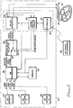
- the preferred embodiment is illustrated embodied in a rate-responsive pacemaker 20 shown in Fig. 1.
- the pacemaker 20 utilizes a first rate-responsive sensor 22 and a second rate-responsive sensor 24.
- the example illustrated as the preferred embodiment of the present invention utilizes two sensors, although more than two sensors could be utilized, as illustrated by an Nth rate-responsive sensor 26 illustrated in phantom lines in Fig. 1.
- the output of the first rate-responsive sensor 22 is identified as raw signal 1
- the output of the second rate-responsive sensor 24 is identified as raw signal 2.
- the outputs of the first rate-responsive sensor 22 and the second rate-responsive sensor 24, the raw signal 1 and the raw signal 2, respectively, are supplied to a rate-responsive processor 28.
- the rate-responsive processor 28 is the heart of the present invention, and its operation will be described in detail below.
- the rate-responsive processor 28 accesses a memory circuit 30, and produces as an output a sensor-indicated rate signal.
- the sensor-indicated rate signal is a signal which indicates the rate which the rate-responsive processor 28 has calculated the pacemaker 20 should use as the pacing rate, based on the inputs from the first rate-responsive sensor 22 and the second rate-responsive sensor 24.
- the pacemaker 20 also includes a conventional pacemaker circuit 32 which typically includes at least a pulse generator 34, a timing and control circuit 36, and a telemetry circuit 38.
- the pulse generator 34 provides electrical pulses to two leads 40 and 42, which provide electrical contact with a patient's heart 44.
- the leads 40 and 42 may be either unipolar leads, bipolar leads, or other multi-pole leads, all of which are known in the art. It should be noted that while the system shown in Fig. 1 is a dual chamber pacemaker, the principles of the present invention could just as easily be applicable to a single chamber pacemaker.
- An external programmer 46 is also used to send programming signals to the telemetry circuit 38. These programming signals are depicted symbolically as a wavy line in Fig. 1. It should be noted that signals may be sent either from the external programmer 46 to the pacemaker 20, or from the pacemaker 20 to the external programmer 46.
- the pulse generator 34 generates stimulation pulses supplied to the leads 40 and 42 at a rate determined by a rate control signal, which is an input to the pulse generator 34. These stimulation pulses, in turn, are delivered to the heart 44 through the leads 40 and 42 in a conventional manner.
- a rate control signal which is an input to the pulse generator 34.
- These stimulation pulses are delivered to the heart 44 through the leads 40 and 42 in a conventional manner.
- the first rate-responsive sensor 22 and the second rate-responsive sensor 24 are shown in Fig. 1 as being included within the pacemaker 20, one or both of the first rate-responsive sensor 22 and the second rate-responsive sensor 24 could also be included within, or coupled to, one of the leads 40 and 42.
- the first rate-responsive sensor 22 and/or the second rate-responsive sensor 24 could also be placed externally of the pacemaker 20.
- the leads 40 and 42 also present electrical signals occurring within the heart 44, such as intracardiac P-waves and R-waves (evidencing natural cardiac activity of the atria and ventricles, respectively), to the timing and control circuit 36.
- intracardiac P-waves and R-waves providing natural cardiac activity of the atria and ventricles, respectively
- the pacemaker 20 is able to inhibit the generation of a pacing pulse when natural cardiac activity is sensed within a designated time period, in a conventional manner.
- the rate-responsive pacemaker 20 may operate in either a SENSOR ON mode or a SENSOR OFF mode.
- the selection of a desired mode of operation is controlled by a sensor on/off selector 48, shown functionally in Fig. 1 as a switch.
- the sensor on/off selector 48 connects either a base rate signal supplied from the timing and control circuit 36 or the sensor-indicated rate signal supplied from the rate-responsive processor 28 as the rate control signal input to the pulse generator 34. Control of the sensor on/off selector 48 is obtained from the timing and control circuit 36, which control may be selected by an appropriate programming signal received from the external programmer 46.
- the sensor on/off selector 48 directs the base rate signal, generated by the timing and control circuit 36, to be the rate control signal input to the pulse generator 34.
- This base rate signal thus controls the pacing rate of the pacemaker 20 in a conventional manner.
- the rate control signal input to the pulse generator 34 is connected by way of the sensor on/off selector 48 to the sensor-indicated rate signal output from the rate-responsive processor 28.
- the sensor-indicated rate signal is derived from the raw signal 1 and the raw signal 2 from the first rate-responsive sensor 22 and the second rate-responsive sensor 24, respectively.
- the rate control signal may be thought of as simply a signal responsible for generating a trigger pulse at the timing out of an escape interval (also generated by the timing and control circuit 36).
- the rate control signal may be thought of as simply a signal responsible for generating a trigger pulse at the timing out of an escape interval (also generated by the timing and control circuit 36).
- no trigger pulse is generated by the pulse generator 34 and the portion of the timing and control circuit 36 responsible for generating the escape interval is reset, thereby starting a new escape interval.
- the rate control signal either the base rate signal from the timing and control circuit 36 or the sensor-indicated rate signal from the rate-responsive processor 28
- such signal may be overridden (if the pacemaker 20 is so programmed) by the sensing of natural cardiac activity.
- signal processing circuitry is used to process raw signal 1 from the first rate-responsive sensor 22 and raw signal 2 from the second rate-responsive sensor 24.
- processing circuitry is known in the art and is not necessarily an integral part of the present invention.
- the amplification, filtering, and linearization may be modified by reprogramming by the external programming unit.
- This processing circuitry may vary widely, so the following description of processing circuitry is merely exemplary.
- a first amplifier 50 is used to amplify raw signal 1 from the first rate-responsive sensor 22.
- the amplified signal from the first amplifier 50 is supplied to a first filter 52 used to minimize the effects of noise on the signal from the first rate-responsive sensor 22.
- the output of the first filter 52 is supplied to a first linearization circuitry 54, which serves to linearize the signal from the first rate-responsive sensor 22 if it varies in a nonlinear fashion.
- Such linearization circuitry is typically a nonlinear amplifier designed to correct the nonlinear response characterizing the sensor.
- the output of the first linearization circuitry 54 is a processed sensor 1 signal.
- a second amplifier 56 is used to amplify raw signal 2 from the second rate-responsive sensor 24.
- the amplified signal from the second amplifier 56 is supplied to a second filter 58 used to minimize the effects of noise on the signal from the second rate-responsive sensor 24.
- the output of the second filter 58 is supplied to a second linearization circuitry 60, which serves to linearize the signal from the second rate-responsive sensor 24 if it varies in a nonlinear fashion.
- the output of the second linearization circuitry 60 is a processed sensor 2 signal.
- the outputs of the first linearization circuitry 54 and the second linearization circuitry 60 are supplied as inputs to a rate matrix logic 62.
- the rate matrix logic 62 accesses the memory circuit 30.
- the operation of the rate matrix logic 62 will become apparent in conjunction with the discussion of Fig. 3 below. At this point, suffice it to say that the rate matrix logic 62 takes the processed sensor 1 signal and the processed sensor 2 signal and from them produces a selected rate.
- the selected rate is indicated by the values of the inputs from the processed sensor 1 signal and the processed sensor 2 signal.
- Each matrix value, Rnm denotes one particular rate.
- the selected rate is supplied as an input to a reaction and recovery time circuit 64.
- the reaction and recovery time circuit 64 serves both to limit the rate at which the pacing rate will be allowed to rise and the rate at which the pacing rate will be allowed to fall.
- the reaction and recovery time circuit 64 will mimic the natural operation of a healthy heart, which is limited in how fast it will change rate.
- the reaction and recovery time circuit 64 is thus used to rate limit the selected rate output from the rate matrix logic 62 in the case when the sensor signal reacts faster than the normal heart, as is the case when an activity sensor is used.
- the output of the reaction and recovery time circuit 64 is the sensor-indicated rate signal.
- reaction and recovery time functions would be to include these functions on the input side of the system rather than on the output side as shown herein.
- Another way of implementing a reaction and recovery time function is by the use of a switch matrix.
- the reaction and recovery time functions may be part of the initial signal processing, instead of being done after the rate matrix processing. In such a system, the slope of the input signals over time would be limited.
- the operation of the rate matrix logic 62 may be explained in conjunction with Fig. 3, which illustrates an example of the rate matrix logic 62.
- the rate matrix illustrated is a 10 by 10 rate matrix, with a total of 100 cells.
- the cells each represent a particular selected rate which will be outputted from the rate matrix logic 62 for a set of specific values for the processed sensor 1 signal and the processed sensor 2 signal.
- the value of the processed sensor 1 signal will be used to select which row the selected rate will be in, and the value of the processed sensor 2 signal will be used to select which column the selected rate will be in. For example, if the processed sensor 1 signal is 32%, the fourth row will be indicated. Similarly, if the processed sensor 2 signal is 78%, the eighth column will be indicated. Thus, for these conditions, the selected rate would be R37.
- the processed sensor 1 signal and the processed sensor 2 signal are both analog signals. This example is made in analog terms for clarity.
- the processed sensor 1 signal and the processed sensor 2 signal would be digital signals used to select the row and column, respectively, of the matrix shown in Fig. 3.
- the implementation of the control circuitry of the present invention could be either analog or digital circuitry.
- the rate matrix logic 62 is a look-up memory device which accesses the memory circuit 30 (typically a RAM) to find the selected rate indicated by the processed sensor 1 signal and the processed sensor 2 signal. It will thus be appreciated by those skilled in the art that the system of the present invention has a unique selected rate for each individual combination of the processed sensor 1 signal and the processed sensor 2 signal. This represents a degree of versatility previously unknown in the art in utilizing inputs from two sensors, and is a tremendous improvement over the art.
- the processed sensor 1 signal and the processed sensor 2 signal values will be sampled at regular intervals, followed by a look-up of the proper selected rate value in the rate matrix. It is apparent that the overall transfer function may be linear or nonlinear in any manner desired. If desired, a threshold value for one or both of the sensors may be built in, requiring the sensor signal to exceed a predetermined level before a rate change is implemented.
- the activity sensor When using an activity sensor together with a slow metabolic sensor, it is easy to allow the activity sensor to have greater influence over the rate in the absence of sensed metabolic activity until the patient has exercised long enough for the metabolic sensor to respond. Similarly, when metabolic activity is sensed, the metabolic sensor may be programmed to have greater influence over the rate than does the activity sensor. The versatility of this system thus retains the advantages of each sensor in a system which is truly better than the sum of its parts.
- the system may be used to combine signals from two sensors, one of which has a good specific response for low levels of exercise (low work levels) and the other of which has a good specific response for high levels of exercise (high work levels).
- the sensor which has a good response for low levels of exercise will be primarily in control during situations when the exercise level is low, and the sensor which has a good response for high levels of exercise will be primarily in control when the exercise level is high.
- the values inscribed in the rate matrix are programmable.
- An external programmer may be used to selectively program each of the rate values stored in the rate matrix.
- the rate matrix may thereby be tailored for different lifestyles, with factors such as age, activity level, and physical condition being used to select the values inscribed in the rate matrix.
- the external programmer may embody an expert system in software to guide the physician to the proper matrix values for various different patient qualities.
- multiple rate matrices may instead be stored in the memory circuit 30 with the rate matrix to be used being programmably selectable.
- the external programmer 46 (Fig. 1) would be used to select a desired rate matrix from the plurality of rate matrices stored in the memory circuit 30.
- the rate matrices thus may be tailored for different lifestyles, with factors such as age, activity level, and physical condition being used to select a desired rate matrix.
- rate matrices are provided, with the particular rate matrix to be used being selected by a switch matrix.
- the criteria used to select which particular rate matrix is to be used may be various timing characteristics of the sensor response, or the satisfaction of various logic conditions. In the preferred embodiment a combination of these criteria is used.
- the rate matrix logic 62 and the memory circuit 30 of Fig. 2 may be replaced by the apparatus shown in Fig. 4.
- the example used in Fig. 4 has an activity sensor utilized as the first rate-responsive sensor 22 (Fig. 1) and a temperature sensor utilized as the second rate-responsive sensor 24 (Fig. 1). It will, of course, be realized by those skilled in the art that any combination of sensors could utilize the principles of operation of the present invention.
- a number of processing circuits receive as inputs the processed sensor 1 signal and the processed sensor 2 signal. These processing circuits provide outputs which are supplied to either a first priority logic circuit 63 or a second priority logic circuit 65.
- the priority logic circuits 63 and 65 each provide an input on one of a plurality of lines to a switch matrix 66. These inputs enable the selection by the switch matrix 66 of a single rate matrix.
- the output from the switch matrix 66 is a switch matrix row number i and a switch matrix column number j, which together identify a particular rate matrix contained in a memory containing rate matrices 68.
- the function of the priority logic circuits 63 and 65 is to receive a number of inputs, more than one of which may be digital ones.
- the priority logic circuits 63 and 65 output signals on a plurality of lines, only one of which from each of the priority logic circuits 63 and 65 may be a digital one at any given time. Therefore, the priority logic circuits 63 and 65 each function to determine which one of a plurality of digital ones received as an input which should be provided as an output to the switch matrix 66.
- a first comparator 70 has as its input the processed sensor 1 signal, and is used to determine whether the processed sensor 1 signal indicated that no activity is being sensed. In Fig. 4 the other input is grounded, but it could be a small threshold signal as well. If no activity (or a level of activity below the threshold) is being sensed, then the first comparator 70 outputs a digital one signal to the first priority logic circuit 63.
- a first timer 72 has as its input the processed sensor 1 signal, and is used to determine whether activity has been sensed for less than A seconds. If activity has in fact been sensed for less than A seconds, then the first timer 72 outputs a digital one signal to the first priority logic circuit 63.
- a second timer 74 has as its input the processed sensor 1 signal, and is used to determine whether activity has been sensed for more than A seconds but less than B seconds, where B seconds is longer than A seconds. If activity has in fact been sensed for more than A seconds but less than B seconds, then the second timer 74 outputs a digital one signal to the first priority logic circuit 63.
- a third timer 76 has as its input the processed sensor 1 signal, and is used to determine whether activity has been sensed for more than C seconds, where C seconds is a considerable length of time indicating prolonged exercise, or a false positive. If activity has in fact been sensed for more than C seconds, then the third timer 76 outputs a digital one signal to the first priority logic circuit 63.
- a high positive slope detector 78 has as its input the processed sensor 1 signal, and is used to detect the existence of a high positive rate of change in the processed sensor 1 signal. If this high positive rate of change in the processed sensor 1 signal is detected by the high positive slope detector 78, and if activity has been sensed for more than B seconds but less than C seconds, then the high positive slope detector 78 outputs a digital one signal to the first priority logic circuit 63.
- a low positive slope detector 80 has as its input the processed sensor 1 signal, and is used to detect the existence of a positive rate of change in the processed sensor 1 signal which is lower than that detected by the high positive slope detector 78. If this lower positive rate of change in the processed sensor 1 signal is detected by the low positive slope detector 80, and if activity has been sensed for more than B seconds but less than C seconds, then the low positive slope detector 80 outputs a digital one signal to the first priority logic circuit 63.
- the high positive slope detector 78 and the low positive slope detector 80 have mutually exclusive digital one outputs.
- a negative slope detector 82 has as its input the processed sensor 1 signal, and is used to detect the existence of a negative rate of change in the processed sensor 1 signal. If a negative rate of change in the processed sensor 1 signal is detected by the negative slope detector 82, and if activity has been sensed for more than B seconds but less than C seconds, then the negative slope detector 82 outputs a digital one signal to the first priority logic circuit 63.
- the priority logic circuits 63 and 65 will determine the relative priority order of the input signals when several of the conditions have been met at the same time. They may also contain sequential circuitry which makes the priority order dependent on preceding inputs. The priority logic may be incorporated wholly or in part as part of the processing circuitry.
- the first priority logic circuit 63 will pass this signal on to the switch matrix 66. If there is a digital one from the first timer 72, the first priority logic circuit 63 will pass this signal on to the switch matrix 66. If there is a digital one signal from the second timer 74, the first priority logic circuit 63 will pass this signal on to the switch matrix 66. If there is a digital one from the third timer 76, the first priority logic circuit 63 will pass this signal on to the switch matrix 66. Signals from the first comparator 70, the first timer 72, the second timer 74, and the third timer 76 are mutually exclusive.
- the first priority logic circuit 63 will pass the signal from the high positive slope detector 78 on to the switch matrix 66.
- the first priority logic circuit 63 will pass the signal from the low positive slope detector 80 on to the switch matrix 66.
- the first priority logic circuit 63 will pass the signal from the negative slope detector 82 on to the switch matrix 66.
- the comparator 70, the first timer 72, the second timer 74, the third timer 76, the high positive slope detector 78, the low positive slope detector 80, and 82 are all used to select the row of the switch matrix 66, as will become apparent below in the discussion in conjunction with Fig. 5. The remaining processing circuitry to be discussed is used to select the column of the switch matrix 66.
- a second comparator 84 has as its input the processed sensor 2 signal, and is used to determine whether the processed sensor 2 signal indicated that no sensor 2 activity is being sensed. In Fig. 4 the other input is grounded, but it could be a small threshold signal as well. If no sensor 2 activity (or a level of activity below the threshold) is being sensed, then the second comparator 84 outputs a digital one signal to the second priority logic circuit 65.
- a third comparator 86 has as inputs the processed sensor 1 signal and the processed sensor 2 signal. If the processed sensor 2 signal is greater than the processed sensor 1 signal, then the third comparator 86 outputs a digital one signal to the second priority logic circuit 65. (This of course would only happen when at least some activity was being sensed by sensor 2, indicating either a high body temperature in the absence of physical activity, or that the second sensor indicates a higher level of exercise than the first sensor. Thus, the second comparator 84 and the third comparator 86 have mutually exclusive digital one outputs.)
- An initial dip detector 88 has as its input the processed sensor 2 signal, and is used to detect an initial dip in temperature characterized by a drop in the processed sensor 2 signal following a long period of inactivity of the processed sensor 2 signal. If this initial dip in the processed sensor 2 is detected by the initial dip detector 88, then the initial dip detector 88 outputs a digital one signal to the second priority logic circuit 65.
- a positive slope detector 90 has as its input the processed sensor 2 signal, and is used to detect the existence of a positive rate of change in the processed sensor 2 signal. If a positive rate of change in the processed sensor 2 signal is detected by the positive slope detector 90, then the positive slope detector 90 outputs a digital one signal to the second priority logic circuit 65.
- a negative slope detector 92 has as its input the processed sensor 2 signal, and is used to detect the existence of a negative rate of change in the processed sensor 2 signal. If a negative rate of change in the processed sensor 2 signal is detected by the negative slope detector 92, then the negative slope detector 92 outputs a digital one signal to the second priority logic circuit 65. If there is a digital one signal from the second comparator 84, the second priority logic circuit 65 will pass this signal on to the switch matrix 66. If there is a digital one signal from the third comparator 86, the second priority logic circuit 65 will pass this signal on to the switch matrix 66. If there is a digital one signal from the initial dip detector 88, and if the output of the fourth comparator 86 is not a digital one signal, the second priority logic circuit 65 will pass the signal from the initial dip detector 88 on to the switch matrix 66.
- the second priority logic circuit 65 will pass the signal from the positive slope detector 90 on to the switch matrix 66. If there is a digital one signal from the negative slope detector 92, and if the output of the fourth comparator 86 is not a digital one signal, and if the output of the initial dip detector 88 is not a digital one signal, the second priority logic circuit 65 will pass the signal from the positive slope detector 90 on to the switch matrix 66.
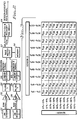
- the switch matrix shown in Fig. 5 is a 7 by 5 switch matrix used to select a specific rate matrix contained in the memory containing rate matrices 68.
- the selection of a cell in the rate matrix of Fig. 5 thus corresponds to the selection of a specific rate matrix intended to optimize the pacemaker rate for the specific conditions identified by the switch matrix.
- the process used to select a specific cell in the switch matrix of Fig. 5 will now be explained. If the first comparator 70 outputs a signal which is provided by the first priority logic circuit 63 to the switch matrix 66, then the first row of the switch matrix of Fig. 5 will be chosen. If the first timer 72 outputs a signal which is provided by the first priority logic circuit 63 to the switch matrix 66, then the second row of the switch matrix of Fig. 5 will be chosen. If the second timer 74 outputs a signal which is provided by the first priority logic circuit 63 to the switch matrix 66, then the third row of the switch matrix of Fig. 5 will be chosen.
- the high positive slope detector 78 outputs a signal which is provided by the first priority logic circuit 63 to the switch matrix 66, then the fourth row of the switch matrix of Fig. 5 will be chosen. If the low positive slope detector 80 outputs a signal which is provided by the first priority logic circuit 63 to the switch matrix 66, then the fifth row of the switch matrix of Fig. 5 will be chosen. If the negative slope detector 82 outputs a signal which is provided by the first priority logic circuit 63 to the switch matrix 66, then the sixth row of the switch matrix of Fig. 5 will be chosen. If the third timer 76 outputs a signal which is provided by the first priority logic circuit 63 to the switch matrix 66, then the seventh row of the switch matrix of Fig. 5 will be chosen.
- the second comparator 84 outputs a signal which is provided by the second priority logic circuit 65 to the switch matrix 66, then the first column of the switch matrix of Fig. 5 will be chosen. If the initial dip detector 88 outputs a signal which is provided by the second priority logic circuit 65 to the switch matrix 66, then the second column of the switch matrix of Fig. 5 will be chosen. If the positive slope detector 90 outputs a signal which is provided by the second priority logic circuit 65 to the switch matrix 66, then the third column of the switch matrix of Fig. 5 will be chosen.
- the negative slope detector 92 outputs a signal which is provided by the second priority logic circuit 65 to the switch matrix 66, then the fourth column of the switch matrix of Fig. 5 will be chosen. If the fourth comparator 86 outputs a signal which is provided by the second priority logic circuit 65 to the switch matrix 66, then the fifth column of the switch matrix of Fig. 5 will be chosen. This completes the selection of a cell, since both a row and a column will have been selected.
- the outputs from the individual sensor processing circuits defining certain conditions of each sensor signal would be interconnected to the switch matrix by a (programmable) logic circuit network which would establish the priority order of the detected conditions. For instance, following a time period with zero signal from the first sensor, the first timer 72 may be given priority over slope detectors 78, 80, and 82.
- the third row in the switch matrix of Fig. 5 will be selected. If the third comparator 86 outputs a signal through the second priority logic circuit 65 to the switch matrix 66 (indicating that the processed sensor 2 signal is greater than the processed sensor 1 signal), the fifth column in the switch matrix of Fig. 5 will be selected. Thus rate matrix RM35 will have been selected.
- the rate matrix RM35 like all the other rate matrices referenced in the switch matrix of Fig. 5, is contained in the memory containing rate matrices 68 of Fig. 4.
- the value of i supplied from the switch matrix 66 to the memory containing rate matrices 68 would be 3, and the value of j supplied from the switch matrix 66 to the memory containing rate matrices 68 would be 5.
- the processed sensor 1 signal and the processed sensor 2 signal are also supplied to the memory containing rate matrices 68, and hence to the selected rate matrix RM35.
- the inputs of the processed sensor 1 signal and the processed sensor 2 signal will enable the selected rate matrix to find the particular cell therein which corresponds to the processed sensor 1 signal and the processed sensor 2 signal. That cell will contain the selected rate, which is output from the memory containing rate matrices 68.
- the balance of the operation is as explained with reference to Figs. 1 and 2.
- the switch matrix 66 is used to analyze the particular circumstances indicated by the signals from the sensors.
- a rate matrix specifically designed for use under the particular circumstances is indicated, and the processed signals from the sensors are supplied to the selected rate matrix, which is contained in the memory containing rate matrices 68.
- a selected rate indicated in the selected rate matrix by the values of the processed signals from the sensors is selected, and used to control the pacing rate of the pacemaker 20.
- the switch matrix would also be programmable using an external programmer. This would even further allow the operation of the pacemaker to be individually tailored by the physician. Again, an expert program would be used to assist the physician in programming the switch matrix.
- the logic circuitry used to drive the switch matrix may also be programmable, at least to some extent. Time values may be programmable in the timers, for example. It may thus be appreciated that the system may be virtually fully programmable, if desired.
- a signal when a signal is first present from the activity sensor it may be allowed to drive the rate to a higher value in the absence of a change in the temperature signal. For example, in the first 45 seconds of action in the activity signal, a high signal from the activity sensor with no activity indicated by a temperature sensor may be allowed to drive the rate of the pacemaker to a high rate.
- a different rate matrix will be accessed causing the selected rate to diminish. For example, in the interval between 45 and 90 seconds after the onset of the activity signal, a high signal from the activity sensor with no activity indicated by the temperature sensor would be allowed to drive the rate of the pacemaker to a moderate rate only.
- a switch matrix may be used in conjunction with only one of the two sensor inputs to the system.
- Fig. 6 the system of Fig. 4 is shown modified so that only the first sensor is used to operate the switch matrix.
- This configuration will work well when one sensor has a nearly ideal response with virtually no artifacts.
- One example of such a sensor is an oxygen saturation sensor.
- the example used in Fig. 6 again has an activity sensor utilized as the first rate-responsive sensor 22 (Fig. 1) and a temperature sensor utilized as the second rate-responsive sensor 24 (Fig. 1). It will, of course, be realized by those skilled in the art that any combination of sensors could utilize the principles of operation of the present invention.
- processing circuits receive as inputs the processed sensor 1 signal. These processing circuits provide outputs which are supplied through the first priority logic circuit 63 as inputs to a switch matrix 96. These inputs enable the selection by the switch matrix 96 of a single rate matrix.
- the output from the switch matrix 96 is a switch matrix row number i which identifies a particular rate matrix contained in a memory containing rate matrices 98.
- the various processing circuitry supplying inputs to the first priority logic circuit 63 are similar to those used in Fig. 4 for the first sensor input.
- the first comparator 70, the first timer 72, the second timer 74, the third timer 76, the high positive slope detector 78, the low positive slope detector 80, and the negative slope detector 82 are used to process the processed sensor 1 signal, and to supply inputs to the memory containing rate matrices 98.
- the operation of these components is the same as explained above in conjunction with Fig. 4.
- the operation of the first priority logic circuit 63 is also the same as explained above in conjunction with Fig. 4.
- the switch matrix shown in Fig. 7 is a 7 by 1 switch matrix used to select a specific rate matrix contained in the memory containing rate matrices 98.
- the selection of a cell in the rate matrix of Fig. 7 thus corresponds to the selection of a specific rate matrix.
- the process used to select a specific cell in the switch matrix of Fig. 7 is analogous to the process used to select a specific row in the system of Fig. 4. If the first comparator 70 outputs a signal through the first priority logic circuit 63 to the switch matrix 96, then the first row of the switch matrix of Fig. 7 will be chosen. If the first timer 72 outputs a signal through the first priority logic circuit 63 to the switch matrix 96, then the second row of the switch matrix of Fig. 7 will be chosen. If the second timer 74 outputs a signal through the first priority logic circuit 63 to the switch matrix 96, then the third row of the switch matrix of Fig. 7 will be chosen.
- the high positive slope detector 78 outputs a signal through the first priority logic circuit 63 to the switch matrix 96, then the fourth row of the switch matrix of Fig. 7 will be chosen. If the low positive slope detector 80 outputs a signal through the first priority logic circuit 63 to the switch matrix 96, then the fifth row of the switch matrix of Fig. 7 will be chosen. If the negative slope detector 82 outputs a signal through the first priority logic circuit 63 to the switch matrix 96, then the sixth row of the switch matrix of Fig. 7 will be chosen. If the third timer 76 outputs a signal through the first priority logic circuit 63 to the switch matrix 96, then the seventh row of the switch matrix of Fig. 7 will be chosen. This completes the selection of a cell, since for the switch matrix of Fig. 7 only a row need be selected.
- the second timer 74 outputs a signal through the first priority logic circuit 63 to the switch matrix 96 (indicating that activity has in fact been sensed for more than A seconds but less than B seconds)
- the third row in the switch matrix of Fig. 7 will be selected.
- rate matrix RM3 will have been selected.
- the rate matrix RM3 like all the other rate matrices referenced in the switch matrix of Fig. 7, is contained in the memory containing rate matrices 98 of Fig. 6.
- the value of i supplied from the switch matrix 96 to the memory containing rate matrices 98 would be 3.
- the processed sensor 1 signal and the processed sensor 2 signal are both supplied to the memory containing rate matrices 98, and hence to the selected rate matrix RM3.
- the inputs of the processed sensor 1 signal and the processed sensor 2 signal will enable the selected rate matrix to find the particular cell therein which corresponds to the processed sensor 1 signal and the processed sensor 2 signal. That cell will contain the selected rate, which is output from the memory containing rate matrices 98.
- the balance of the operation is again as explained with reference to Figs. 1 and 2.
- the system of the present invention utilizes the best properties of each of the sensors, while minimizing or eliminating their drawbacks.
- the control strategy is of a complexity sufficient to provide as an output a highly flexible sensor-indicated rate signal which will accurately follow a control strategy paralleling the physiological response of a healthy heart.
- the control strategy of the preferred embodiment of the present invention is also fully programmable by using an external programmer.
- the implementation of the present invention is relatively simple and easy to accomplish in a pacemaker, and will not increase the size of the pacemaker.
- the system of the present invention is useable with two sensors, and is capable of working with more than two sensors.
- the system is also economic of power, and does not require more power to operate than do other rate-response processors.
Landscapes
- Health & Medical Sciences (AREA)
- Life Sciences & Earth Sciences (AREA)
- Heart & Thoracic Surgery (AREA)
- Cardiology (AREA)
- Engineering & Computer Science (AREA)
- Physiology (AREA)
- Biophysics (AREA)
- Biomedical Technology (AREA)
- Nuclear Medicine, Radiotherapy & Molecular Imaging (AREA)
- Radiology & Medical Imaging (AREA)
- Animal Behavior & Ethology (AREA)
- General Health & Medical Sciences (AREA)
- Public Health (AREA)
- Veterinary Medicine (AREA)
- Electrotherapy Devices (AREA)
Claims (12)
- Herzschrittmacher (20) mit veränderbarer Stimulationsrate zum Stimulieren des Herzens (44) eines Patienten, wobei der Herzschrittmacher (20) umfaßt:Pulserzeugungseinrichtung (34) zum Erzeugen und Zuführen von Stimulationsimpulsen an das Herz des Patienten (44) in Antwort auf ein ausgewähltes Taktsignal;eine erste Sensoreinrichtung (22) zum Detektieren eines ersten physiologischen Parameters eines Patienten und zum Herstellen eines ersten Signales in Antwort darauf;eine zweite Sensoreinrichtung (24) zum Detektieren eines zweiten physiologischen Parameters eines Patienten und zum Herstellen eines zweiten Signales in Antwort darauf;eine erste Umwandlungseinrichtung (50-54) zum Umwandeln des ersten Signales in ein erstes Adressensignal;eine zweite Umwandlungseinrichtung (56-60) zum Umwandeln des zweiten Signales in ein zweites Adressensignal; undeine adressierbare Taktmatrix (62,30,RM), die als Eingange die ersten und zweiten Adressensignale hat und die als einen Ausgang ein gemeinsam ausgewähltes Taktsignal hat, welches mit den Werten der ersten und zweiten Adressensignale korrespondiert, wobei das ausgewählte Taktsignal an die Pulserzeugungseinrichtung (34) geliefert wird.
- Herzschrittmacher (20) mit veranderbarer Stimulationsrate nach Anspruch 1, worin die erste Sensoreinrichtung (22) eine relativ schnelle Antwort hat und die zweite Sensoreinrichtung (24) eine relativ langsame Antwort hat.
- Herzschrittmacher (20) mit veränderbarer Stimulationsrate nach Anspruch 2, worin die erste Sensoreinrichtung (22) einen der Sensoren aus der Gruppe, die aus einem Aktivitätssensor, einem Blutsauerstoffsättigungssensor, einem Blutsauerstoffpartialdrucksensor und einem PCO2-Sensor besteht, umfaßt, und worin die zweite Sensoreinrichtung (24) einen der Sensoren aus der Gruppe, die aus einem Atmungsminutenvolumensensor, einem Temperatursensor, einem Atmungstaktsensor, einem intrakardialen Drucksensor, einem Schlagvolumensensor, einem intrakardialen Elektrokardiogrammorphologiesensor, einem Blut-pH-Sensor, und einem QT-Intervallsensor besteht, umfaßt.
- Herzschrittmacher (20) mit veranderbarer Stimulationsrate nach Anspruch 1, worin die erste Sensoreinrichtung (22) eine sehr fehlerfreie Antwort für niedrige Ausübungsgrade hat und die zweite Sensoreinrichtung (24) eine sehr fehlerfreie Antwort für hohe Ausübungsgrade hat.
- Herzschrittmacher (20) mit veranderbarer Stimulationsrate nach Anspruch 4, worin die erste Sensoreinrichtung (22) einen der Sensoren aus der Gruppe, die einen Aktivitätssensor, einen Blutsauerstoffsättigungssensor, einem Blutsauerstoffpartialdrucksensor und einem PCO2-Sensor besteht, umfaßt, und worin die zweite Sensoreinrichtung (24) einen der Sensoren aus der Gruppe, die aus einem Atmungsminutenvolumensensor, einem Temperatursensor, einem intrakardialen Drucksensor, einem Schlagvolumensensor, einem intrakardialen Elektrokardiogrammorphologiesensor und einem QT-Intervallsensor besteht, umfaßt.
- Herzschrittmacher (20) mit veranderbarer Stimulationsrate nach einem der vorangegangenen Ansprüche, worin die erste Umwandlungseinrichtung (50-54) umfaßt:einen ersten Verstärker (50) zum Verstärken des ersten Signales, wobei der erste Verstärker (50) einen ersten Verstärkerausgang hat;einen ersten Filter (52) zum Filtern des ersten Verstärkerausganges, wobei der erste Filter (52) einen ersten Filterausgang hat; undeine erste Linearisierungseinrichtung (54) zum Linearisieren des ersten Filterausganges, und worin die zweite Umwandlungseinrichtung (56-60) umfaßt:einen zweiten Verstärker (56) zum Verstärken des zweiten Signales, wobei der zweite Verstärker (56) einen zweiten Verstärkerausgang hat;einen zweiten Filter (58) zum Filtern des zweiten Verstärkerausganges, wobei der zweite Filter (58) einen zweiten Filterausgang hat; undzweite Linearisierungseinrichtung (60) zum Linearisieren des zweiten Filterausganges.
- Herzschrittmacher (20) mit veränderbarer Stimulationsrate nach einem der vorangegangenen Ansprüche, worin die adressierbare Taktmatrrx (30,62) umfaßt:Speicher (30) zum Speichern einer Vielzahl von Taktsignalen; undTaktspeicherungslogikeinrichtung (62) zum Auswählen von einem der Taktsignale, die in dem Speicher (30) gespeichert sind, welche mit dem ersten und dem zweiten Adressensignalen korrespondieren.
- Herzschrittmacher (20) mit veränderbarer Stimulationsrate nach einem der vorangegangenen Ansprüche, zusätzlich umfassend:eine Reaktions- und Erholungszeitschaltung (64), die zwischen der adressierbaren Taktmatrix (62,30) und der Pulserzeugungseinrichtung (34) installiert ist, wobei die Reaktions- und Erholungszeitschaltung (64) zum Begrenzen des Taktes, bei welchem das ausgewählte Taktsignal, das an die Pulserzeugungseinrichtung (34) geliefert wird, es ermöglicht wird, anzusteigen oder zu fallen, gedacht ist.
- Herzschrittmacher (20) mit veränderbarer Stimulationsrate nach einem der vorangegangenen Ansprüche, zusätzlich umfassend:mindestens eine weitere Sensoreinrichtung (26) zum Detektieren eines weiteren physiologischen Parameters eines Patienten und zum Herstellen eines weiteren Signales in Antwort darauf;mindestens eine weitere Umwandlungseinrichtung zum Umwandeln des weiteren Signales in ein weiteres Adressensignal, worin die adressierbare Taktmatrix ebenfalls als einen Eingang das weitere Adressensignal hat, und worin der gemeinsame ausgewählte Taktsignalausgang aus der adressierbaren Taktmatrix mit den Werten der ersten, zweiten und weiteren Adressensignalen korrespondiert.
- Herzschrittmacher (20) mit veränderbarer Stimulationsrate nach einem der vorangegangenen Ansprüche, zusätzlich umfassend:mindestens eine zusätzlich adressierbare Taktmatrix (RM), die als Eingänge die ersten und zweiten Adressensignale hat und die als einen Ausgang ein gemeinsames ausgewähltes Taktsignal hat, das mit den Werten der ersten und zweiten Adressensignalen korrespondiert; undEinrichtung (63-92) zum Auswählen, ob der Ausgang von der adressierten Taktmatrix (RM) oder der Ausgang von mindestens einer zusätzlichen Taktmatrix (RM) an die Pulserzeugungseinrichtung (34) geliefert werden wird, wobei die Auswähleinrichtung (63-92) als Eingang mindestens das erste Signal hat.
- Herzschrittmacher (20) mit veränderbarer Stimulationsrate nach Anspruch 10, worin die Auswähleinrichtung (63,92) umfaßt:erste Verarbeitungseinrichtung (63,70-82) zum Verarbeiten des ersten Signales, um ein erstes Schaltmatrix-Eingangssignal, das eines oder mehrere Kennzeichen des ersten Signales zeigt, zu liefern; undeine adressierbare Schaltmatrix (96), die als Eingänge das erste Schaltmatrixeingangssignal hat und als einen Ausgang ein Signal hat, das aus einem der adressierbaren Taktmatricen (98, RM) und aus mindestens einer der zusätzlichen Taktmatricen (RM), die mit den Werten des ersten Matrixeingangssignales korrespondieren, ausgewählt wird.
- Herzschrittmacher (20) mit veränderbarer Stimulationsrate nach Anspruch 11, worin die Auswahleinrichtung (63-92) weiterhin umfaßt:eine zweite Verarbeitungseinrichtung (65,86-92) zum Verarbeiten des zweiten Signales, um ein zweites Schaltmatrix-Eingangssignal zu liefern, das eines oder mehrere Kennzeichen des zweiten Signales anzeigt.
Applications Claiming Priority (2)
| Application Number | Priority Date | Filing Date | Title |
|---|---|---|---|
| US509645 | 1990-04-16 | ||
| US07/509,645 US5101824A (en) | 1990-04-16 | 1990-04-16 | Rate-responsive pacemaker with circuitry for processing multiple sensor inputs |
Publications (3)
| Publication Number | Publication Date |
|---|---|
| EP0452733A2 EP0452733A2 (de) | 1991-10-23 |
| EP0452733A3 EP0452733A3 (en) | 1993-02-03 |
| EP0452733B1 true EP0452733B1 (de) | 1996-12-18 |
Family
ID=24027518
Family Applications (1)
| Application Number | Title | Priority Date | Filing Date |
|---|---|---|---|
| EP91105271A Revoked EP0452733B1 (de) | 1990-04-16 | 1991-04-03 | Herzschrittmacher mit veränderbarer Stimulationsrate und mit einer Schaltung zur Verarbeitung von mehrfachen Sensor- eingängen |
Country Status (5)
| Country | Link |
|---|---|
| US (1) | US5101824A (de) |
| EP (1) | EP0452733B1 (de) |
| JP (1) | JPH04227280A (de) |
| AU (1) | AU633236B2 (de) |
| DE (1) | DE69123625T2 (de) |
Families Citing this family (66)
| Publication number | Priority date | Publication date | Assignee | Title |
|---|---|---|---|---|
| US5097831A (en) * | 1990-04-16 | 1992-03-24 | Siemens-Pacesetter, Inc. | Rate-responsive pacemaker with circuitry for processing multiple sensor inputs |
| US5282837A (en) * | 1991-04-12 | 1994-02-01 | Incontrol, Inc. | Atrial defibrillator and method |
| US5395393A (en) * | 1991-11-01 | 1995-03-07 | Telectronics Pacing Systems, Inc. | Intracardiac electrogram sensing in an arrhythmia control system |
| US5423867A (en) * | 1992-03-02 | 1995-06-13 | Pacesetter, Inc. | Rate-responsive pacemaker having automatic sensor threshold with programmable offset |
| US5312453A (en) * | 1992-05-11 | 1994-05-17 | Medtronic, Inc. | Rate responsive cardiac pacemaker and method for work-modulating pacing rate deceleration |
| US5372607A (en) * | 1993-06-23 | 1994-12-13 | Medtronic, Inc. | Method and apparatus for monitoring pacemaker intervals |
| US5441524A (en) * | 1993-08-30 | 1995-08-15 | Medtronic, Inc. | Energy efficient multiple sensor cardiac pacemaker |
| US5376106A (en) * | 1993-10-18 | 1994-12-27 | Cardiac Pacemakers, Inc. | Multi-sensor blending in a rate responsive cardiac pacemaker |
| US5626622A (en) | 1994-09-21 | 1997-05-06 | Telectronics Pacing Systems, Inc. | Dual sensor rate responsive pacemaker |
| US5562711A (en) * | 1994-11-30 | 1996-10-08 | Medtronic, Inc. | Method and apparatus for rate-responsive cardiac pacing |
| DE4447447C2 (de) * | 1994-12-29 | 2000-07-06 | Pacesetter Ab Jaerfaella | Herzschrittmacher |
| SE9600511D0 (sv) * | 1996-02-12 | 1996-02-12 | Pacesetter Ab | Bipolar sensor electrode |
| US5929318A (en) * | 1997-05-02 | 1999-07-27 | Illinois Instruments, Inc. | System and method for sensing low levels of a particular gas in an atmosphere |
| US7110817B2 (en) * | 1998-05-08 | 2006-09-19 | Cardiac Pacemakers, Inc. | Method and apparatus for optimizing ventricular synchrony during DDD resynchronization therapy using adjustable atrio-ventricular delays |
| US6144880A (en) * | 1998-05-08 | 2000-11-07 | Cardiac Pacemakers, Inc. | Cardiac pacing using adjustable atrio-ventricular delays |
| US7158830B2 (en) * | 1998-05-08 | 2007-01-02 | Cardiac Pacemakers, Inc. | Method and apparatus for optimizing stroke volume during DDD resynchronization therapy using adjustable atrio-ventricular delays |
| US6055454A (en) * | 1998-07-27 | 2000-04-25 | Cardiac Pacemakers, Inc. | Cardiac pacemaker with automatic response optimization of a physiologic sensor based on a second sensor |
| US7142918B2 (en) * | 2000-12-26 | 2006-11-28 | Cardiac Pacemakers, Inc. | Apparatus and method for pacing mode switching during atrial tachyarrhythmias |
| US6430438B1 (en) | 1999-05-21 | 2002-08-06 | Cardiac Pacemakers, Inc. | Cardiac rhythm management system with atrial shock timing optimization |
| US8064997B2 (en) * | 1999-05-21 | 2011-11-22 | Cardiac Pacemakers, Inc. | Method and apparatus for treating irregular ventricular contractions such as during atrial arrhythmia |
| US7181278B2 (en) * | 1999-05-21 | 2007-02-20 | Cardiac Pacemakers, Inc. | Apparatus and method for ventricular rate regularization |
| US7212860B2 (en) * | 1999-05-21 | 2007-05-01 | Cardiac Pacemakers, Inc. | Apparatus and method for pacing mode switching during atrial tachyarrhythmias |
| US7062325B1 (en) * | 1999-05-21 | 2006-06-13 | Cardiac Pacemakers Inc | Method and apparatus for treating irregular ventricular contractions such as during atrial arrhythmia |
| US6285907B1 (en) | 1999-05-21 | 2001-09-04 | Cardiac Pacemakers, Inc. | System providing ventricular pacing and biventricular coordination |
| US6501988B2 (en) | 2000-12-26 | 2002-12-31 | Cardiac Pacemakers Inc. | Apparatus and method for ventricular rate regularization with biventricular sensing |
| US7239914B2 (en) * | 2000-05-13 | 2007-07-03 | Cardiac Pacemakers, Inc. | Rate smoothing control |
| US6501987B1 (en) * | 2000-05-26 | 2002-12-31 | Cardiac Pacemakers, Inc. | Rate smoothing control |
| US7039461B1 (en) * | 2000-05-13 | 2006-05-02 | Cardiac Pacemakers, Inc. | Cardiac pacing system for prevention of ventricular fibrillation and ventricular tachycardia episode |
| US8512220B2 (en) * | 2000-05-26 | 2013-08-20 | Cardiac Pacemakers, Inc. | Rate smoothing control |
| US6424865B1 (en) | 2000-07-13 | 2002-07-23 | Cardiac Pacemakers, Inc. | Ventricular conduction delay trending system and method |
| US6829504B1 (en) * | 2000-09-14 | 2004-12-07 | Cardiac Pacemakers, Inc. | System and method for preventing recurrence of atrial tachyarrhythmia |
| US6512951B1 (en) | 2000-09-14 | 2003-01-28 | Cardiac Pacemakers, Inc. | Delivery of atrial defibrillation shock based on estimated QT interval |
| US6564098B1 (en) * | 2000-11-06 | 2003-05-13 | Medtronic, Inc. | Method and system for increasing a pacer function of an implantable medical device disposed within a mammalian heart |
| US20020087198A1 (en) * | 2000-12-29 | 2002-07-04 | Kramer Andrew P. | Apparatus and method for ventricular rate regularization |
| US6957100B2 (en) * | 2000-12-26 | 2005-10-18 | Cardiac Pacemakers, Inc. | Method and system for display of cardiac event intervals in a resynchronization pacemaker |
| US6952612B1 (en) | 2002-04-24 | 2005-10-04 | Pacesetter, Inc. | Method and apparatus for programming a rate responsive implantable cardiac stimulation device using user specified rate response functions |
| CN101134119A (zh) | 2002-05-24 | 2008-03-05 | 血管技术国际股份公司 | 用于涂覆医用植入物的组合物和方法 |
| US7184835B2 (en) * | 2003-12-12 | 2007-02-27 | Cardiac Pacemakers, Inc. | Method and apparatus for adjustable AVD programming using a table |
| US20060058852A1 (en) * | 2004-09-10 | 2006-03-16 | Steve Koh | Multi-variable feedback control of stimulation for inspiratory facilitation |
| US7155281B1 (en) | 2004-12-03 | 2006-12-26 | Pacesetter, Inc. | Complimentary activity sensor network for disease monitoring and therapy modulation in an implantable device |
| WO2006138380A2 (en) * | 2005-06-15 | 2006-12-28 | Massachusetts Institute Of Technology | Amine-containing lipids and uses thereof |
| US8175703B2 (en) * | 2006-01-25 | 2012-05-08 | Cardiac Pacemakers, Inc. | Cardiac resynchronization therapy parameter optimization |
| WO2009075725A1 (en) | 2007-12-13 | 2009-06-18 | Cardiac Pacemakers, Inc. | Supraventricular tachy sensing vector |
| WO2009151516A2 (en) | 2008-05-08 | 2009-12-17 | Cardiac Pacemakers, Inc. | Smart delay for intermittent stress therapy |
| EP3269395A1 (de) | 2008-11-07 | 2018-01-17 | Massachusetts Institute Of Technology | Aminoalkohol-lipoide und verwendungen davon |
| EP3318248B1 (de) | 2009-12-01 | 2019-04-10 | Translate Bio, Inc. | Ausgabe von mrna zur vermehrung von proteinen und enzymen bei humangenetischen erkrankungen |
| US9193827B2 (en) | 2010-08-26 | 2015-11-24 | Massachusetts Institute Of Technology | Poly(beta-amino alcohols), their preparation, and uses thereof |
| EP2691443B1 (de) | 2011-03-28 | 2021-02-17 | Massachusetts Institute of Technology | Konjugierte lipomers und ihre verwendung |
| RU2013154295A (ru) | 2011-06-08 | 2015-07-20 | Шир Хьюман Дженетик Терапис, Инк. | КОМПОЗИЦИИ ЛИПИДНЫХ НАНОЧАСТИЦ И СПОСОБЫ ДЛЯ ДОСТАВКИ мРНК |
| WO2013090118A2 (en) | 2011-12-12 | 2013-06-20 | Cardiac Pacemakers, Inc. | Heart rate variability and heart rate variation |
| WO2013185067A1 (en) | 2012-06-08 | 2013-12-12 | Shire Human Genetic Therapies, Inc. | Nuclease resistant polynucleotides and uses thereof |
| JP6586075B2 (ja) | 2013-03-14 | 2019-10-02 | トランスレイト バイオ, インコーポレイテッド | メッセンジャーrnaの精製方法 |
| RS57739B1 (sr) | 2013-03-14 | 2018-12-31 | Translate Bio Inc | Kompozicije cftr irnk i postupci i upotrebe u vezi sa njima |
| WO2014179562A1 (en) | 2013-05-01 | 2014-11-06 | Massachusetts Institute Of Technology | 1,3,5-triazinane-2,4,6-trione derivatives and uses thereof |
| CN106413811A (zh) | 2013-10-22 | 2017-02-15 | 夏尔人类遗传性治疗公司 | 精氨基琥珀酸合成酶缺乏症的mrna疗法 |
| JP6506749B2 (ja) | 2013-10-22 | 2019-04-24 | シャイアー ヒューマン ジェネティック セラピーズ インコーポレイテッド | フェニルケトン尿症のためのmRNA療法 |
| ES3032935T3 (en) | 2013-10-22 | 2025-07-29 | Translate Bio Inc | Lipid formulations for delivery of messenger rna |
| US9850269B2 (en) | 2014-04-25 | 2017-12-26 | Translate Bio, Inc. | Methods for purification of messenger RNA |
| JP6557722B2 (ja) | 2014-05-30 | 2019-08-07 | シャイアー ヒューマン ジェネティック セラピーズ インコーポレイテッド | 核酸の送達のための生分解性脂質 |
| KR102559979B1 (ko) | 2014-06-24 | 2023-07-25 | 샤이어 휴먼 지네틱 테라피즈 인크. | 핵산의 전달용 입체화학적으로 풍부한 조성물 |
| US9840479B2 (en) | 2014-07-02 | 2017-12-12 | Massachusetts Institute Of Technology | Polyamine-fatty acid derived lipidoids and uses thereof |
| EA201991747A1 (ru) | 2017-02-27 | 2020-06-04 | Транслейт Био, Инк. | НОВАЯ КОДОН-ОПТИМИЗИРОВАННАЯ мРНК CFTR |
| MX2019013752A (es) | 2017-05-16 | 2020-07-20 | Translate Bio Inc | Tratamiento de la fibrosis quística mediante el suministro de arnm que codifica cftr optimizado en codones. |
| KR102950141B1 (ko) | 2018-08-24 | 2026-04-07 | 트랜슬레이트 바이오 인코포레이티드 | 전령 rna의 정제 방법 |
| WO2020106946A1 (en) | 2018-11-21 | 2020-05-28 | Translate Bio, Inc. | TREATMENT OF CYSTIC FIBROSIS BY DELIVERY OF NEBULIZED mRNA ENCODING CFTR |
| EP4031662A1 (de) | 2019-09-20 | 2022-07-27 | Translate Bio, Inc. | Mrna-codierendes technisches cftr |
Family Cites Families (8)
| Publication number | Priority date | Publication date | Assignee | Title |
|---|---|---|---|---|
| JPS6138135A (ja) * | 1984-07-27 | 1986-02-24 | Fuji Heavy Ind Ltd | 自動車用エンジンの空燃比制御方式 |
| DE3506789A1 (de) * | 1985-02-22 | 1986-08-28 | Biotronik Meß- und Therapiegeräte GmbH & Co Ingenieurbüro Berlin, 1000 Berlin | Demand-herzschrittmacher mit physiologischer steuerung |
| EP0225839B1 (de) * | 1985-09-17 | 1993-12-01 | BIOTRONIK Mess- und Therapiegeräte GmbH & Co Ingenieurbüro Berlin | Herzschrittmacher |
| DE3687206D1 (de) * | 1985-09-17 | 1993-01-14 | Biotronik Mess & Therapieg | Herzschrittmacher. |
| EP0215730B1 (de) * | 1985-09-17 | 1993-06-16 | BIOTRONIK Mess- und Therapiegeräte GmbH & Co Ingenieurbüro Berlin | Herzschrittmacher |
| DE3631155A1 (de) * | 1986-09-12 | 1988-03-24 | Alt Eckhard | Frequenzvariabler herzschrittmacher mit belastungsadaequatem frequenzverhalten |
| US4895151A (en) * | 1987-07-20 | 1990-01-23 | Telectronics N.V. | Apparatus and method for therapy adjustment in implantable |
| US5097831A (en) * | 1990-04-16 | 1992-03-24 | Siemens-Pacesetter, Inc. | Rate-responsive pacemaker with circuitry for processing multiple sensor inputs |
-
1990
- 1990-04-16 US US07/509,645 patent/US5101824A/en not_active Expired - Lifetime
-
1991
- 1991-04-03 EP EP91105271A patent/EP0452733B1/de not_active Revoked
- 1991-04-03 DE DE69123625T patent/DE69123625T2/de not_active Revoked
- 1991-04-08 AU AU74207/91A patent/AU633236B2/en not_active Ceased
- 1991-04-15 JP JP3109810A patent/JPH04227280A/ja active Pending
Also Published As
| Publication number | Publication date |
|---|---|
| EP0452733A2 (de) | 1991-10-23 |
| JPH04227280A (ja) | 1992-08-17 |
| AU7420791A (en) | 1991-10-17 |
| DE69123625D1 (de) | 1997-01-30 |
| US5101824A (en) | 1992-04-07 |
| EP0452733A3 (en) | 1993-02-03 |
| AU633236B2 (en) | 1993-01-21 |
| DE69123625T2 (de) | 1997-04-17 |
Similar Documents
| Publication | Publication Date | Title |
|---|---|---|
| EP0452733B1 (de) | Herzschrittmacher mit veränderbarer Stimulationsrate und mit einer Schaltung zur Verarbeitung von mehrfachen Sensor- eingängen | |
| EP0452732B1 (de) | Taktempfindlicher Herzschrittmacher mit einer Schaltung zur Steuerung von mehrfachen Sensoreingängen | |
| US5549649A (en) | Programmable pacemaker including an atrial rate filter for deriving a filtered atrial rate used for switching pacing modes | |
| EP0431083B1 (de) | Herzschrittmacher mit selbsttätiger einstellung der taktantwort | |
| US5040534A (en) | Microprocessor controlled rate-responsive pacemaker having automatic rate response threshold adjustment | |
| US5226413A (en) | Rate responsive pacemaker and method for automatically initializing the same | |
| US4856523A (en) | Rate-responsive pacemaker with automatic mode switching and/or variable hysteresis rate | |
| EP1509280B1 (de) | Implantierbares medizinisches gerät mit autosensitivitätsalgorithmus zur steuerung der detektion von herzsignalen | |
| US5423869A (en) | Multi-sensor rate-responsive pacemaker and method of operating same | |
| US4945909A (en) | Pacemaker with activity-dependent rate limiting | |
| US8260418B2 (en) | System for waveform stimulation compensating electrode polarization | |
| US5741308A (en) | Dual-chamber implantable pacemaker and method of operating same for automatically setting the pacemaker's AV interval as a function of a natural measured conduction time | |
| EP0796129B1 (de) | Herzschrittmacher mit sinus-präferenz verfahren | |
| US5387229A (en) | Multi-sensor cardiac pacemaker with sensor event recording capability | |
| EP0726082A2 (de) | Frequenzadaptiver Schrittmacher | |
| EP0559193A2 (de) | Implantierbarer Herzschrittmacher welcher eine Hysterese bei Zweikammerbetriebart erzeugt | |
| US6128533A (en) | Pacemaker with automatic PVARP adjustment during automatic mode switching | |
| US6754532B1 (en) | Coronary sinus flow regulated pacing | |
| EP0709114B1 (de) | Zweikammer-Herzschrittmacher-System mit verbesserter Umschaltung zwischen dem synchronen und dem asynchronen Modus | |
| US6650937B2 (en) | Method and system for gradual cardiac training using an implantable medical device | |
| US5226414A (en) | Implantable cardiac pacemaker with extended atrial sensing | |
| EP1321167B1 (de) | Herzschrittmacher | |
| EP0804940A2 (de) | Frequenzadaptiver Herzschrittmacher mit automatischer Auswahl des Faktors der Taktantwort | |
| US6952612B1 (en) | Method and apparatus for programming a rate responsive implantable cardiac stimulation device using user specified rate response functions |
Legal Events
| Date | Code | Title | Description |
|---|---|---|---|
| PUAI | Public reference made under article 153(3) epc to a published international application that has entered the european phase |
Free format text: ORIGINAL CODE: 0009012 |
|
| AK | Designated contracting states |
Kind code of ref document: A2 Designated state(s): DE FR GB IT NL SE |
|
| PUAL | Search report despatched |
Free format text: ORIGINAL CODE: 0009013 |
|
| AK | Designated contracting states |
Kind code of ref document: A3 Designated state(s): DE FR GB IT NL SE |
|
| 17P | Request for examination filed |
Effective date: 19930308 |
|
| RAP1 | Party data changed (applicant data changed or rights of an application transferred) |
Owner name: PACESETTER AB |
|
| 17Q | First examination report despatched |
Effective date: 19950222 |
|
| RAP1 | Party data changed (applicant data changed or rights of an application transferred) |
Owner name: PACESETTER, INC. |
|
| GRAG | Despatch of communication of intention to grant |
Free format text: ORIGINAL CODE: EPIDOS AGRA |
|
| GRAH | Despatch of communication of intention to grant a patent |
Free format text: ORIGINAL CODE: EPIDOS IGRA |
|
| GRAH | Despatch of communication of intention to grant a patent |
Free format text: ORIGINAL CODE: EPIDOS IGRA |
|
| ITF | It: translation for a ep patent filed | ||
| GRAA | (expected) grant |
Free format text: ORIGINAL CODE: 0009210 |
|
| AK | Designated contracting states |
Kind code of ref document: B1 Designated state(s): DE FR GB IT NL SE |
|
| REF | Corresponds to: |
Ref document number: 69123625 Country of ref document: DE Date of ref document: 19970130 |
|
| ET | Fr: translation filed | ||
| PG25 | Lapsed in a contracting state [announced via postgrant information from national office to epo] |
Ref country code: SE Effective date: 19970318 |
|
| PLBQ | Unpublished change to opponent data |
Free format text: ORIGINAL CODE: EPIDOS OPPO |
|
| PLBI | Opposition filed |
Free format text: ORIGINAL CODE: 0009260 |
|
| PLBF | Reply of patent proprietor to notice(s) of opposition |
Free format text: ORIGINAL CODE: EPIDOS OBSO |
|
| 26 | Opposition filed |
Opponent name: BIOTRONIK MESS- UND THERAPIEGERAETE GMBH & CO ING Effective date: 19970917 |
|
| NLR1 | Nl: opposition has been filed with the epo |
Opponent name: BIOTRONIK MESS- UND THERAPIEGERAETE GMBH & CO INGE |
|
| PGFP | Annual fee paid to national office [announced via postgrant information from national office to epo] |
Ref country code: GB Payment date: 19980325 Year of fee payment: 8 |
|
| PLBF | Reply of patent proprietor to notice(s) of opposition |
Free format text: ORIGINAL CODE: EPIDOS OBSO |
|
| PLBF | Reply of patent proprietor to notice(s) of opposition |
Free format text: ORIGINAL CODE: EPIDOS OBSO |
|
| PG25 | Lapsed in a contracting state [announced via postgrant information from national office to epo] |
Ref country code: GB Free format text: LAPSE BECAUSE OF NON-PAYMENT OF DUE FEES Effective date: 19990403 |
|
| GBPC | Gb: european patent ceased through non-payment of renewal fee |
Effective date: 19990403 |
|
| PGFP | Annual fee paid to national office [announced via postgrant information from national office to epo] |
Ref country code: NL Payment date: 20010322 Year of fee payment: 11 |
|
| PLBQ | Unpublished change to opponent data |
Free format text: ORIGINAL CODE: EPIDOS OPPO |
|
| PLAB | Opposition data, opponent's data or that of the opponent's representative modified |
Free format text: ORIGINAL CODE: 0009299OPPO |
|
| PLBO | Opposition rejected |
Free format text: ORIGINAL CODE: EPIDOS REJO |
|
| R26 | Opposition filed (corrected) |
Opponent name: BIOTRONIK MESS- UND THERAPIEGERAETE GMBH & CO INGE Effective date: 19970917 |
|
| APAC | Appeal dossier modified |
Free format text: ORIGINAL CODE: EPIDOS NOAPO |
|
| APAE | Appeal reference modified |
Free format text: ORIGINAL CODE: EPIDOS REFNO |
|
| NLR1 | Nl: opposition has been filed with the epo |
Opponent name: BIOTRONIK MESS- UND THERAPIEGERAETE GMBH & CO INGE |
|
| APAC | Appeal dossier modified |
Free format text: ORIGINAL CODE: EPIDOS NOAPO |
|
| PG25 | Lapsed in a contracting state [announced via postgrant information from national office to epo] |
Ref country code: NL Free format text: LAPSE BECAUSE OF NON-PAYMENT OF DUE FEES Effective date: 20021101 |
|
| NLV4 | Nl: lapsed or anulled due to non-payment of the annual fee |
Effective date: 20021101 |
|
| PGFP | Annual fee paid to national office [announced via postgrant information from national office to epo] |
Ref country code: FR Payment date: 20040420 Year of fee payment: 14 |
|
| PLAB | Opposition data, opponent's data or that of the opponent's representative modified |
Free format text: ORIGINAL CODE: 0009299OPPO |
|
| PGFP | Annual fee paid to national office [announced via postgrant information from national office to epo] |
Ref country code: DE Payment date: 20040601 Year of fee payment: 14 |
|
| R26 | Opposition filed (corrected) |
Opponent name: BIOTRONIK GMBH & CO. KG Effective date: 19970917 |
|
| APBU | Appeal procedure closed |
Free format text: ORIGINAL CODE: EPIDOSNNOA9O |
|
| RDAF | Communication despatched that patent is revoked |
Free format text: ORIGINAL CODE: EPIDOSNREV1 |
|
| RDAG | Patent revoked |
Free format text: ORIGINAL CODE: 0009271 |
|
| STAA | Information on the status of an ep patent application or granted ep patent |
Free format text: STATUS: PATENT REVOKED |
|
| 27W | Patent revoked |
Effective date: 20041012 |
|
| APAH | Appeal reference modified |
Free format text: ORIGINAL CODE: EPIDOSCREFNO |