EP0452740B1 - Dispositif d'analyse de liquides - Google Patents
Dispositif d'analyse de liquides Download PDFInfo
- Publication number
- EP0452740B1 EP0452740B1 EP91105321A EP91105321A EP0452740B1 EP 0452740 B1 EP0452740 B1 EP 0452740B1 EP 91105321 A EP91105321 A EP 91105321A EP 91105321 A EP91105321 A EP 91105321A EP 0452740 B1 EP0452740 B1 EP 0452740B1
- Authority
- EP
- European Patent Office
- Prior art keywords
- test
- test field
- carrier according
- layer package
- base part
- Prior art date
- Legal status (The legal status is an assumption and is not a legal conclusion. Google has not performed a legal analysis and makes no representation as to the accuracy of the status listed.)
- Expired - Lifetime
Links
Images

Classifications
-
- G—PHYSICS
- G01—MEASURING; TESTING
- G01N—INVESTIGATING OR ANALYSING MATERIALS BY DETERMINING THEIR CHEMICAL OR PHYSICAL PROPERTIES
- G01N33/00—Investigating or analysing materials by specific methods not covered by groups G01N1/00 - G01N31/00
- G01N33/48—Biological material, e.g. blood, urine; Haemocytometers
- G01N33/50—Chemical analysis of biological material, e.g. blood, urine; Testing involving biospecific ligand binding methods; Immunological testing
- G01N33/52—Use of compounds or compositions for colorimetric, spectrophotometric or fluorometric investigation, e.g. use of reagent paper and including single- and multilayer analytical elements
- G01N33/528—Atypical element structures, e.g. gloves, rods, tampons, toilet paper
-
- G—PHYSICS
- G01—MEASURING; TESTING
- G01N—INVESTIGATING OR ANALYSING MATERIALS BY DETERMINING THEIR CHEMICAL OR PHYSICAL PROPERTIES
- G01N33/00—Investigating or analysing materials by specific methods not covered by groups G01N1/00 - G01N31/00
- G01N33/48—Biological material, e.g. blood, urine; Haemocytometers
- G01N33/50—Chemical analysis of biological material, e.g. blood, urine; Testing involving biospecific ligand binding methods; Immunological testing
- G01N33/52—Use of compounds or compositions for colorimetric, spectrophotometric or fluorometric investigation, e.g. use of reagent paper and including single- and multilayer analytical elements
- G01N33/525—Multi-layer analytical elements
-
- Y—GENERAL TAGGING OF NEW TECHNOLOGICAL DEVELOPMENTS; GENERAL TAGGING OF CROSS-SECTIONAL TECHNOLOGIES SPANNING OVER SEVERAL SECTIONS OF THE IPC; TECHNICAL SUBJECTS COVERED BY FORMER USPC CROSS-REFERENCE ART COLLECTIONS [XRACs] AND DIGESTS
- Y10—TECHNICAL SUBJECTS COVERED BY FORMER USPC
- Y10S—TECHNICAL SUBJECTS COVERED BY FORMER USPC CROSS-REFERENCE ART COLLECTIONS [XRACs] AND DIGESTS
- Y10S435/00—Chemistry: molecular biology and microbiology
- Y10S435/805—Test papers
-
- Y—GENERAL TAGGING OF NEW TECHNOLOGICAL DEVELOPMENTS; GENERAL TAGGING OF CROSS-SECTIONAL TECHNOLOGIES SPANNING OVER SEVERAL SECTIONS OF THE IPC; TECHNICAL SUBJECTS COVERED BY FORMER USPC CROSS-REFERENCE ART COLLECTIONS [XRACs] AND DIGESTS
- Y10—TECHNICAL SUBJECTS COVERED BY FORMER USPC
- Y10S—TECHNICAL SUBJECTS COVERED BY FORMER USPC CROSS-REFERENCE ART COLLECTIONS [XRACs] AND DIGESTS
- Y10S435/00—Chemistry: molecular biology and microbiology
- Y10S435/97—Test strip or test slide
Definitions
- the invention relates to a test carrier for the analysis of liquids with a frame surrounding a test field opening, consisting of at least two parts, and a test field arranged in the test field opening.
- test carriers So-called carrier-bound tests are increasingly being used for the qualitative or quantitative analytical determination of constituents of liquids, in particular body fluids of humans or animals.
- reagents are embedded in the test layers of an analysis element, which is referred to as a test carrier. You will be brought into contact with the sample. The reaction of sample and reagents leads to a detectable Signal, in particular a color change, which can be evaluated visually or with the aid of a device, usually by reflection photometry.
- Numerous different types of test carriers are known which differ not only with regard to the reagents used, but also with their structure, in particular with regard to the arrangement and attachment of the test layers. The following two types are of particular practical importance.
- Strip-shaped test carriers of the first type essentially consist of an elongated base layer made of plastic material and test layers applied thereon.
- the connection between the test layers and the plastic carrier is usually made by gluing, whereby the gluing is often not on the entire surface, but only on one edge of the test layer, or additional fasteners (nets or fastening foils) are attached to the base layer, which indirectly connect the test layers hold tight.
- the test layers can be produced independently of one another and assembled during the final assembly of the strip-shaped test carrier.
- EP-A-0 269 876 shows an example of the combined use of materials of different structures, which do not form an integral composite, as test carriers.
- the test layer package formed from a reaction matrix body and a tissue-like base layer lies on the entire surface of a voluminous absorber.
- the test field package is not provided in a frame.
- the absorber body is required as a pressure surface for achieving the test layer contact.
- test carriers with frames and in the English language literature as "analysis slides”.
- analysis slides The sample is usually applied to the test field through the test field opening. After the test reaction, the color formation can be observed or measured - usually on the side of the test field facing away from the sample side.
- test fields consisting of several separate test layers have been used with this type of test carrier.
- the test field usually consists of a transparent plastic film as a carrier, which is successively coated with various layer-forming liquids in which the reagents or auxiliary components for carrying out the test are contained.
- a multi-layer structure is also possible here, however, the test field consists of a one-piece layer composite, the individual layers of which are connected to one another over the entire surface. This is necessary to enable the test fields to be easily installed in the frame and, above all, to ensure uniform fluid contact between the individual layers. This uniform liquid contact is a prerequisite for an exact analysis, because an uneven liquid transfer between the individual test layers results in an inhomogeneous color formation, which considerably impairs the measuring accuracy. It should also be taken into account that the individual layers should be as thin as possible in order to keep the required amount of sample and reagents as small as possible and still achieve intensive color formation.
- test layer composite The need to produce the test field for test carriers with frames as a one-piece layer composite leads to considerable restrictions when using this type of test carrier.
- the development of the test layer composite is very complex. Manufacturing is also difficult because the accuracy of the analysis depends on the fact that each individual layer is manufactured with very tight tolerances in a consistent quality. Naturally, this is more difficult to achieve if the layers are applied successively in the form of a layer-forming liquid than if the test layers are produced completely separately from one another and are only joined together during the final assembly of the test carrier.
- fiber composite structures woven or nonwovens
- particle composite structures e.g. EP-A-00 13 156) each have special properties that are advantageous for certain purposes.
- the combined use of such different structures is only possible to a very limited extent.
- the invention is therefore based on the object of providing a test carrier with a frame in which it is possible to assemble the test field from a plurality of test layers produced separately from one another.
- the accuracy of the analysis should not be impaired and the test carrier should be produced efficiently.
- test carrier of the type described at the outset by the features of the characterizing part of claim 1.
- test layer package with several test layers that are not fully connected to one another as a test field in the previously known test carriers with frames therefore leads to an uneven liquid transfer between the test layers and thus to poor analysis accuracy because the inevitable, albeit relatively small, thickness tolerances of conventional test fields led to a very different pressure load on the test field package. It has been found that this problem can be avoided by ensuring that the pressure with which the pressure surface presses on the test layer package is essentially constant within the tolerance range of the thickness of the test field package. "Substantially constant” is to be understood in such a way that the constant pressure and the uniformity of the liquid transfer between the test layers which is dependent on it must ensure the desired accuracy of measurement.
- the pressure of the pressure surface on the test layer package should change by less than 20% if its thickness changes by 0.01 mm.
- the base part and / or the cover part itself can be made of a sufficiently elastic material, or elastically resilient spring elements (for example a pressure ring made of a highly elastic material) can be used.
- particularly preferred embodiments assume that a plastic with a relatively low intrinsic elasticity is used and that the elastic compliance is achieved by appropriate design of the cover part and / or base part including their connecting elements. This enables a simple construction with small dimensions; the hard frame material is preferred because of the handling properties, in particular during the fully mechanical processing of the test carriers in corresponding automatic analyzers.
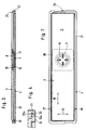
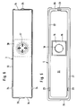
- the test carrier 1 shown in FIG. 1 has a flat, preferably less than 3 mm, particularly preferably only about 2 mm thick frame 2, which consists of a cover part 3 and a base part 4.
- a test field opening 6 In the center of the upper frame surface 5 there is a test field opening 6 through which the test field is visible.
- the test field is designed as a test layer package 7 consisting of three loosely lying test layers 10, 11, 12. They perform various functions in the test process.
- the first test layer 10 can be a covering net which protects the layers underneath and at the same time contains a wetting agent which promotes the spreading of the sample.
- Layer 11 can be used to separate the erythrocytes from the blood sample.
- a glass fiber fleece according to US Pat. No. 4,477,575 is suitable, for example.
- Layer 12 can be a reagent film, for example, which contains a reagent system which leads to a color change on the underside of layer 12 which is characteristic of the analysis. Details of the test procedure are not important for the present invention.
- test sequence is such that the sample is placed on one side of the test layer package, which can be referred to as sample application side 13, and the measurement or visual evaluation of the detection signal on the other side of the test layer package (detection side 14) through a second test field opening 9 takes place, which usually has the same size as the test field opening 6.
- the layer package has fluctuations in thickness due to production, which are for example in the order of plus / minus 0.02 mm.
- the layers must lie reliably on one another over the entire surface so that a uniform transfer of the sample from one layer to another is achieved. Even relatively small differences in the pressure lead to spotty color formation, as was recognized in the context of the present invention.
- the layer package 7 lies in a flat receptacle 16 which is formed in the base part 4.
- the cover part 3 has a pressure surface 17.
- the pressure surface surrounds the test field opening in a ring. But it can also be designed in a different way. If, for example, the opening 6 is to be as large as the test layers 12 or even somewhat larger, the pressure surface can only be formed from the underside of pressure tongues protruding into the test field opening.
- the use of pressure tongues has also proven to be advantageous in that capillary gaps between the underside of the pressure tongues and the uppermost test layer 10 promote the absorption of the sample into the test layer.
- the pressure surface 17 is in any case on the uppermost test layer 10 of the test layer package 7. "Above” is to be understood as the side facing the cover part. This does not necessarily have to be the sample feed side.
- the receptacle 16 is formed in the case shown as a tub surrounded by a closed wall. However, other means, in particular pins or wall pieces with spaces, can also be used to position the test layer package 7. They are commonly called Positioning device 15 denotes. Between the inner boundary 15a of the positioning device 15 facing the test layer package 7 and the outer boundary 17a of the pressure surface 17 there is preferably an annular gap R which is large enough to prevent the sample liquid from being sucked into the annular gap R by capillary forces. It is preferably at least 0.1 mm, particularly preferably at least 0.3 mm, wide.
- Adhesive-free, discrete connecting elements 25, 26, 27 are preferably used to connect the cover part 3 to the base part 4, which are preferably designed such that they each have form-fitting abutting limiting elements 23a, 24a that limit the relative movement perpendicular to the plane of the test layer package 7 (FIG. 4 ) exhibit.
- the cover part 3 has a projection 24, the upper surface of which forms one of the delimiting elements.
- the base part 4 has recesses 23 which are open towards the center of the frame 2 and on which the boundary elements 23a on the base part side are formed. The projections 24 engage in the recesses 23.
- a projection 24 and a recess 23 each form a connecting element 25, 26, 27.
- connection elements are possible, but it is advantageous if they are designed such that on the one hand they limit the relative movement between the cover part and the base part in the direction perpendicular to the test layers 10 to 12, while on the other hand they limit the elastic deformation of the cover part 3 and Allow base part 4 to facilitate slight relative movement of both parts in the direction parallel to the surface of test layers 10 to 12.
- the connecting elements 25, 26, 27 are preferably designed as a clip connection, the interlocking ones Parts 23, 24 are slightly deformed elastically during assembly in order to bring them into engagement with one another.
- the clip connection must be designed so that it cannot come loose during the elastic deformation according to the invention.
- the base part 4 has an edge profile 21 which is thickened relative to its base surface 20 and on which the clip connections are formed.
- both are fixed with relatively few discrete adhesive-free connecting elements with respect to a relative movement perpendicular to the plane of the test field and these are relatively far apart.
- their distance should be at least three times the diameter of the test field opening 6.
- the elasticity with which the pressure surface 17 is pressed against the test field package 7 can be ensured in that at least one of the plastic profile parts in the vicinity of the test field opening 6 or 9 has a particularly low material thickness.
- the material thickness here is preferably less than 0.3 mm, particularly preferably less than 0.2 mm.
- the elastic region 28 has at least as large an area as that Test field opening 6.9. If these are different, the information refers to the larger of the two test field openings.
- the positioning device 15, which surrounds the receptacle 16 in the base part 6, is higher than the test layer package 7. Since it is preferably in the elastic range 28, there is sufficient space for this despite the low overall height of the frame 2.
- the high positioning device 15 ensures that the test layers 10, 11, 12 do not fall out in spite of the vibrations that are unavoidable during mechanical assembly.
- cover part and the base part are positioned exactly in relation to one another in the direction of their surface dimensions indicated by the arrows 30 and 31 in FIG. 7.
- the cover part has a narrow circumferential fitting bar 32 which bears against the inner wall 22 of the edge profile 21 of the base part 20. The exact assembly is facilitated by a positioning lug 33.
- the cover part 3 and the base part 4 are preferably injection molded from polystyrene or ABS (acrylonitrile butadiene styrene). Recessing recesses 34 and 35 are expediently provided on their edges, against which the casting pins are in contact during the manufacturing process.
Landscapes
- Health & Medical Sciences (AREA)
- Life Sciences & Earth Sciences (AREA)
- Hematology (AREA)
- Immunology (AREA)
- Engineering & Computer Science (AREA)
- Molecular Biology (AREA)
- Biomedical Technology (AREA)
- Chemical & Material Sciences (AREA)
- Urology & Nephrology (AREA)
- Food Science & Technology (AREA)
- Biochemistry (AREA)
- Cell Biology (AREA)
- Biotechnology (AREA)
- Medicinal Chemistry (AREA)
- Physics & Mathematics (AREA)
- Analytical Chemistry (AREA)
- Microbiology (AREA)
- General Health & Medical Sciences (AREA)
- General Physics & Mathematics (AREA)
- Pathology (AREA)
- Investigating Or Analysing Biological Materials (AREA)
- Investigating Or Analyzing Non-Biological Materials By The Use Of Chemical Means (AREA)
- Investigating Or Analysing Materials By The Use Of Chemical Reactions (AREA)
- Devices For Use In Laboratory Experiments (AREA)
Claims (9)
- Support de test pour l'analyse de liquides, avec un cadre (2) constitué d'au moins deux parties, entourant un orifice de zone de test (6), et une zone de test disposée dans l'orifice de zone de test (6), caractérisé en ce que
la zone de test est constituée d'un empilement de couches de test (7), avec au moins deux couches de test (10, 11, 12) superposées, reliées entre elles seulement par une partie de leur surface,
le cadre (2) comprend deux profilés en matière plastique, le premier profilé servant de partie de base (4) et présentant une cavité (16) pour les couches de test (10, 11, 12), le second profilé servant de partie de couverture (3) et présentant une surface de pression (17) reposant sur la couche de test supérieure (10) de l'empilement de couches de test (7), et
le cadre est conçu sous forme élastique, de façon que la pression exercée par la surface de pression (17) sur l'empilement de couches de test (7) varie dans une proportion inférieure à 20 % lorsque l'épaisseur de l'empilement de couches de test (7) varie de 0,01 mm. - Support de test selon l'une quelconque des revendications précédentes, caractérisé en ce que la partie de couverture (3) et la partie de base (4) sont reliées entre elles par l'intermédiaire d'au moins deux éléments de liaison (25, 26, 27), qui présentent chacun des éléments de bordure (23a, 24a) superposés, en contact mécanique mutuel, délimitant le déplacement relatif des parties (3, 4) perpendiculairement au plan de l'empilement de couches de test (7).
- Support de test selon la revendication 2, caractérisé en ce que la distance entre les éléments de liaison (25, 26 ,27) est au moins trois fois supérieure au diamètre de l'orifice de zone de test (6, 7).
- Support de test selon l'une des revendications 2 ou 3, caractérisé en ce que les éléments de liaison (25, 26 ,27) sont réalisés sous forme de clip de serrage.
- Support de test selon la revendication 4, caractérisé en ce que la partie de couverture (3) ou la partie de base (4) présente un profil de bordure (21) plus épais que la plus grande partie de sa surface, et le clip de serrage vient s'encliqueter dans le profil de bordure (21).
- Support de test selon l'une quelconque des revendications précédentes, caractérisé en ce qu'au moins l'un des profilés (4) en matière plastique présente une zone d'élasticité (28) qui possède une superficie totale au moins aussi importante que l'orifice de zone de test (6, 7) et une épaisseur de matériau inférieure à 0,3 mm, de préférence inférieure à 0,2 mm.
- Support de test selon l'une quelconque des revendications précédentes, caractérisé en ce que la cavité (16) de la partie de base (4) est entourée d'un dispositif de positionnement (15) pour l'empilement de couches de test (7), la hauteur de ce dispositif étant supérieure à celle de l'empilement de couches de test (7).
- Support de test selon l'une quelconque des revendications précédentes, caractérisé en ce qu'entre la limite extérieure (17a) de la surface de pression (17) prévue sur la partie de couverture (3) et la limite intérieure (15a) du dispositif de positionnement (15), tournée vers l'empilement de couches de test (7), il est prévu une fente annulaire.
- Support de test selon l'une quelconque des revendications précédentes, caractérisé en ce qu'il comporte des languettes de pression (8) qui pénètrent dans l'orifice de zone de test (6).
Applications Claiming Priority (2)
| Application Number | Priority Date | Filing Date | Title |
|---|---|---|---|
| DE4012216A DE4012216A1 (de) | 1990-04-14 | 1990-04-14 | Testtraeger fuer die analyse von fluessigkeiten |
| DE4012216 | 1990-04-14 |
Publications (2)
| Publication Number | Publication Date |
|---|---|
| EP0452740A1 EP0452740A1 (fr) | 1991-10-23 |
| EP0452740B1 true EP0452740B1 (fr) | 1995-10-18 |
Family
ID=6404509
Family Applications (2)
| Application Number | Title | Priority Date | Filing Date |
|---|---|---|---|
| EP91105321A Expired - Lifetime EP0452740B1 (fr) | 1990-04-14 | 1991-04-04 | Dispositif d'analyse de liquides |
| EP91907144A Expired - Lifetime EP0477322B1 (fr) | 1990-04-14 | 1991-04-12 | Support de test pour l'analyse de liquides |
Family Applications After (1)
| Application Number | Title | Priority Date | Filing Date |
|---|---|---|---|
| EP91907144A Expired - Lifetime EP0477322B1 (fr) | 1990-04-14 | 1991-04-12 | Support de test pour l'analyse de liquides |
Country Status (8)
| Country | Link |
|---|---|
| US (1) | US5173261A (fr) |
| EP (2) | EP0452740B1 (fr) |
| JP (2) | JP2895976B2 (fr) |
| AT (2) | ATE129345T1 (fr) |
| CA (2) | CA2039882A1 (fr) |
| DE (3) | DE4012216A1 (fr) |
| ES (2) | ES2078373T3 (fr) |
| WO (1) | WO1991016626A1 (fr) |
Families Citing this family (29)
| Publication number | Priority date | Publication date | Assignee | Title |
|---|---|---|---|---|
| US4935346A (en) | 1986-08-13 | 1990-06-19 | Lifescan, Inc. | Minimum procedure system for the determination of analytes |
| US5258163A (en) * | 1990-04-14 | 1993-11-02 | Boehringer Mannheim Gmbh | Test carrier for analysis of fluids |
| DE4132743A1 (de) * | 1991-10-02 | 1993-04-08 | Boehringer Mannheim Gmbh | Testtraeger fuer die analyse von fluessigkeiten |
| US5958339A (en) * | 1992-08-31 | 1999-09-28 | Clinical Diagnostic Systems, Inc. | Format for immunoassay in thin film |
| JP3299330B2 (ja) * | 1993-03-18 | 2002-07-08 | 持田製薬株式会社 | 簡易測定装置および方法 |
| US6096269A (en) * | 1993-08-05 | 2000-08-01 | Charlton; Steven C. | Analyte detection device and process |
| US5824491A (en) * | 1996-05-17 | 1998-10-20 | Mercury Diagnostics, Inc. | Dry reagent test strip comprising benzidine dye precursor and antipyrine compound |
| US6267722B1 (en) | 1998-02-03 | 2001-07-31 | Adeza Biomedical Corporation | Point of care diagnostic systems |
| US6394952B1 (en) | 1998-02-03 | 2002-05-28 | Adeza Biomedical Corporation | Point of care diagnostic systems |
| USD434153S (en) * | 1998-04-20 | 2000-11-21 | Adeza Biomedical Corporation | Point of care analyte detector system |
| USD432244S (en) * | 1998-04-20 | 2000-10-17 | Adeza Biomedical Corporation | Device for encasing an assay test strip |
| US6458326B1 (en) | 1999-11-24 | 2002-10-01 | Home Diagnostics, Inc. | Protective test strip platform |
| EP1203563A3 (fr) * | 2000-10-31 | 2004-01-02 | Boehringer Mannheim Gmbh | Moyen d'analyse avec lancette intégrée |
| US6525330B2 (en) | 2001-02-28 | 2003-02-25 | Home Diagnostics, Inc. | Method of strip insertion detection |
| US6541266B2 (en) | 2001-02-28 | 2003-04-01 | Home Diagnostics, Inc. | Method for determining concentration of an analyte in a test strip |
| US6562625B2 (en) | 2001-02-28 | 2003-05-13 | Home Diagnostics, Inc. | Distinguishing test types through spectral analysis |
| US6740293B1 (en) | 2001-07-17 | 2004-05-25 | Biotech Atlantic, Inc. | Housing for test strip device and test strip therefor |
| US20040018973A1 (en) * | 2002-01-25 | 2004-01-29 | University Of Pittsburgh | Nuclear matrix protein alterations associated with colon cancer and colon metastasis to the liver, and uses thereof |
| US7323139B2 (en) * | 2002-07-26 | 2008-01-29 | Quantum Design, Inc. | Accessible assay and method of use |
| US20040156747A1 (en) * | 2002-08-26 | 2004-08-12 | Lattec I/S | Testing device for testing or analysing fluids and a holder and a storage container for such devices |
| DE10349914A1 (de) * | 2002-10-29 | 2004-05-13 | Roche Diagnostics Gmbh | Testelementanlaysesystem |
| US8262991B2 (en) * | 2003-05-19 | 2012-09-11 | Lattec I/S | Apparatus for analysing fluid taken from a body |
| WO2005123952A2 (fr) * | 2004-06-09 | 2005-12-29 | Pathogen Removal And Diagnostic Technologies Inc. | Dispositfs et procedes d'elimination d'agents cibles d'un echantillon |
| EP1774389B1 (fr) * | 2004-08-05 | 2014-06-18 | JPK Instruments AG | Dispositif pour recevoir un echantillon d'essai |
| PL2244086T3 (pl) | 2006-04-08 | 2021-11-22 | F. Hoffmann-La Roche Ag | Analiza danych optycznych za pomocą histogramów |
| EP1997429B1 (fr) | 2007-05-29 | 2011-11-23 | Roche Diagnostics GmbH | Lancet flexible en une systeme de lancettes |
| KR101439790B1 (ko) * | 2013-09-12 | 2014-09-12 | 유승국 | 진단 키트 제조 장치 및 이에 의해 제조된 진단 키트 |
| EP3246704B1 (fr) * | 2015-01-16 | 2020-01-01 | Fujifilm Corporation | Kit d'immunochromatographie |
| JP6440261B2 (ja) * | 2016-01-25 | 2018-12-19 | 株式会社シン・コーポレイション | ラテラルフロー検査方法 |
Family Cites Families (31)
| Publication number | Priority date | Publication date | Assignee | Title |
|---|---|---|---|---|
| FR352690A (fr) * | 1905-03-24 | 1905-08-17 | August Hildebrand | Moyeu à roue libre et frein pour cycles |
| NO770196L (no) * | 1976-01-22 | 1977-07-25 | Wellcome Found | Kjemiske pr¦vesystemer. |
| JPS542715U (fr) * | 1977-06-08 | 1979-01-09 | ||
| US4254083A (en) * | 1979-07-23 | 1981-03-03 | Eastman Kodak Company | Structural configuration for transport of a liquid drop through an ingress aperture |
| JPS56101537A (en) * | 1980-01-18 | 1981-08-14 | Fuji Photo Film Co Ltd | Use of chemical analytical slide |
| JPH0131957Y2 (fr) * | 1980-03-28 | 1989-10-02 | ||
| JPS6057223B2 (ja) * | 1980-10-14 | 1985-12-13 | 富士通株式会社 | ワイヤボンディング方法 |
| JPS5832350U (ja) * | 1981-08-19 | 1983-03-02 | コニカ株式会社 | 分析素子用マウント |
| JPS58105043A (ja) * | 1981-12-10 | 1983-06-22 | イ−ストマン コダック カンパニ− | 定量分析法 |
| JPS6014141A (ja) * | 1983-07-06 | 1985-01-24 | Kyoto Daiichi Kagaku:Kk | 多層一体化分析用具 |
| JPS6079265A (ja) * | 1983-10-06 | 1985-05-07 | Fuji Photo Film Co Ltd | 分析スライドカ−トリツジおよび分析スライド供給方法 |
| JPS60104767U (ja) * | 1983-11-24 | 1985-07-17 | コニカ株式会社 | 化学分析スライド |
| CA1235361A (fr) * | 1984-03-13 | 1988-04-19 | Paul W. Jeffrey | Production de feuilles d'alliage l'aluminium et articles connexes |
| DE3585780D1 (de) * | 1984-12-24 | 1992-05-07 | Abbott Lab | Analytische vorrichtung und verfahren zu ihrer verwendung. |
| US4678757A (en) * | 1985-04-11 | 1987-07-07 | Smithkline Diagnostics, Inc. | Device and method for whole blood separation and analysis |
| JPS61205068U (fr) * | 1985-06-14 | 1986-12-24 | ||
| JPS62157553A (ja) * | 1985-12-30 | 1987-07-13 | Konishiroku Photo Ind Co Ltd | 生化学分析装置 |
| US4916056A (en) * | 1986-02-18 | 1990-04-10 | Abbott Laboratories | Solid-phase analytical device and method for using same |
| JPS62217159A (ja) * | 1986-03-19 | 1987-09-24 | Fuji Photo Film Co Ltd | 化学分析スライドの製造方法 |
| JPS6339873A (ja) * | 1986-08-05 | 1988-02-20 | Tokuyama Soda Co Ltd | パ−フルオロジ(β−サルトン)類 |
| EP0269876B1 (fr) * | 1986-11-24 | 1993-08-18 | Abbott Laboratories | Dispositif de concentration d'échantillon pour un appareil analytique de phase solide |
| JPH0750095B2 (ja) * | 1987-02-10 | 1995-05-31 | 富士写真フイルム株式会社 | 化学分析スライドの連続製造装置 |
| JPS63256840A (ja) * | 1987-04-14 | 1988-10-24 | Fuji Photo Film Co Ltd | 分析スライド |
| JPS63148973A (ja) * | 1987-07-08 | 1988-06-21 | 大日精化工業株式会社 | かぎ煙草 |
| US5006464A (en) * | 1987-10-01 | 1991-04-09 | E-Y Laboratories, Inc. | Directed flow diagnostic device and method |
| US5073340A (en) * | 1987-10-08 | 1991-12-17 | Becton, Dickinson And Company | Depositing a binder on a solid support |
| JPH01124559U (fr) * | 1988-02-17 | 1989-08-24 | ||
| ATE105634T1 (de) * | 1988-03-23 | 1994-05-15 | Becton Dickinson Co | Vorrichtung zur abgabe einer fluessigen probe auf ein diagnostisches geraet in reguliertem ausmass. |
| DE3814370A1 (de) * | 1988-04-28 | 1989-11-09 | Boehringer Mannheim Gmbh | Testtraeger fuer die analyse einer probenfluessigkeit, verfahren zur durchfuehrung einer solchen analyse und herstellungsverfahren |
| US5106758A (en) * | 1988-12-12 | 1992-04-21 | Technicon Instruments Corporation | Analytical test device and the use thereof |
| US5104619A (en) * | 1990-01-24 | 1992-04-14 | Gds Technology, Inc. | Disposable diagnostic system |
-
1990
- 1990-04-14 DE DE4012216A patent/DE4012216A1/de not_active Withdrawn
-
1991
- 1991-04-04 AT AT91105321T patent/ATE129345T1/de not_active IP Right Cessation
- 1991-04-04 ES ES91105321T patent/ES2078373T3/es not_active Expired - Lifetime
- 1991-04-04 EP EP91105321A patent/EP0452740B1/fr not_active Expired - Lifetime
- 1991-04-04 DE DE59106701T patent/DE59106701D1/de not_active Expired - Fee Related
- 1991-04-05 CA CA002039882A patent/CA2039882A1/fr not_active Abandoned
- 1991-04-11 JP JP3079313A patent/JP2895976B2/ja not_active Expired - Fee Related
- 1991-04-12 DE DE59105779T patent/DE59105779D1/de not_active Expired - Fee Related
- 1991-04-12 WO PCT/DE1991/000310 patent/WO1991016626A1/fr not_active Ceased
- 1991-04-12 CA CA002057059A patent/CA2057059C/fr not_active Expired - Fee Related
- 1991-04-12 EP EP91907144A patent/EP0477322B1/fr not_active Expired - Lifetime
- 1991-04-12 US US07/778,096 patent/US5173261A/en not_active Expired - Fee Related
- 1991-04-12 JP JP3506742A patent/JPH0765995B2/ja not_active Expired - Fee Related
- 1991-04-12 ES ES91907144T patent/ES2073746T3/es not_active Expired - Lifetime
- 1991-04-12 AT AT91907144T patent/ATE124142T1/de not_active IP Right Cessation
Also Published As
| Publication number | Publication date |
|---|---|
| DE4012216A1 (de) | 1991-10-17 |
| JPH04503716A (ja) | 1992-07-02 |
| JPH0765995B2 (ja) | 1995-07-19 |
| EP0477322B1 (fr) | 1995-06-21 |
| DE59106701D1 (de) | 1995-11-23 |
| EP0452740A1 (fr) | 1991-10-23 |
| ES2078373T3 (es) | 1995-12-16 |
| WO1991016626A1 (fr) | 1991-10-31 |
| JPH04225146A (ja) | 1992-08-14 |
| DE59105779D1 (de) | 1995-07-27 |
| CA2057059A1 (fr) | 1991-10-15 |
| ES2073746T3 (es) | 1995-08-16 |
| US5173261A (en) | 1992-12-22 |
| JP2895976B2 (ja) | 1999-05-31 |
| CA2039882A1 (fr) | 1991-10-06 |
| EP0477322A1 (fr) | 1992-04-01 |
| ATE124142T1 (de) | 1995-07-15 |
| CA2057059C (fr) | 1999-08-10 |
| ATE129345T1 (de) | 1995-11-15 |
Similar Documents
| Publication | Publication Date | Title |
|---|---|---|
| EP0452740B1 (fr) | Dispositif d'analyse de liquides | |
| EP0618443B1 (fr) | Analyseur pour bandes de test | |
| DE3688159T2 (de) | Kombinierter Wasch- und Saugapparat. | |
| EP0535480B1 (fr) | Support de test pour l'analyse de liquides | |
| EP0340562B1 (fr) | Elément de test pour analyse d'agglutination, méthode de fabrication et utilisation | |
| EP0634215A1 (fr) | Dispositif pour la détermination simultanée d'analytes | |
| DE69822577T2 (de) | Kugelgelenkverschluss mit Verriegelungseinrichtung für Probenaufnahmebehälter | |
| DE69405116T2 (de) | Nachweis vorrichtung und herstellungsverfahren dafür | |
| DE69030690T2 (de) | Verdampfungsabdeckungen | |
| DE60121467T2 (de) | Abdeckungsanordnung für mikrotestplatte | |
| DE2163147B2 (de) | Vorrichtung zur Durchführung von Gel-Diffusionstests | |
| DE3523439A1 (de) | Testtraeger | |
| EP0443161B1 (fr) | Support d'essai pour l'analyse d'un échantillon fluide | |
| DE69920331T2 (de) | Behälter für Flüssigkeiten, insbesondere zur Analyse biologischer Flüssigkeiten | |
| DE60223345T2 (de) | Membranventil mit umfangsdichtung | |
| DE19960306A1 (de) | Ventilelement und Verfahren zum Herstellen desselben | |
| DE69617283T2 (de) | Vorrichtung zum Anpressen von Elementen in einer Kassette für trockene chemische Analyseelemente | |
| DE4307437A1 (fr) | ||
| DE3816748A1 (de) | Hydraulikaggregat | |
| DE69103437T2 (de) | Vorrichtung zum automatischen Verschliessen einer Pipettenspitze. | |
| DE4428385A1 (de) | Ventilkörper | |
| DE112020003503T5 (de) | Flüssigkeitsprobentestvorrichtung | |
| DE69228386T2 (de) | Verbindungstyp-vorrichtung für mikrolitermengen | |
| DE4306310C2 (de) | Gewebeeinbettbehälter mit Einsatz | |
| EP0389777B1 (fr) | Plaque collective de raccord |
Legal Events
| Date | Code | Title | Description |
|---|---|---|---|
| PUAI | Public reference made under article 153(3) epc to a published international application that has entered the european phase |
Free format text: ORIGINAL CODE: 0009012 |
|
| 17P | Request for examination filed |
Effective date: 19910404 |
|
| AK | Designated contracting states |
Kind code of ref document: A1 Designated state(s): AT BE CH DE DK ES FR GB GR IT LI LU NL SE |
|
| 17Q | First examination report despatched |
Effective date: 19931217 |
|
| GRAA | (expected) grant |
Free format text: ORIGINAL CODE: 0009210 |
|
| AK | Designated contracting states |
Kind code of ref document: B1 Designated state(s): AT BE CH DE DK ES FR GB GR IT LI LU NL SE |
|
| PG25 | Lapsed in a contracting state [announced via postgrant information from national office to epo] |
Ref country code: NL Free format text: LAPSE BECAUSE OF FAILURE TO SUBMIT A TRANSLATION OF THE DESCRIPTION OR TO PAY THE FEE WITHIN THE PRESCRIBED TIME-LIMIT Effective date: 19951018 Ref country code: GR Free format text: LAPSE BECAUSE OF FAILURE TO SUBMIT A TRANSLATION OF THE DESCRIPTION OR TO PAY THE FEE WITHIN THE PRESCRIBED TIME-LIMIT Effective date: 19951018 Ref country code: DK Effective date: 19951018 Ref country code: BE Effective date: 19951018 |
|
| REF | Corresponds to: |
Ref document number: 129345 Country of ref document: AT Date of ref document: 19951115 Kind code of ref document: T |
|
| ITF | It: translation for a ep patent filed | ||
| REF | Corresponds to: |
Ref document number: 59106701 Country of ref document: DE Date of ref document: 19951123 |
|
| ET | Fr: translation filed | ||
| GBT | Gb: translation of ep patent filed (gb section 77(6)(a)/1977) |
Effective date: 19951113 |
|
| REG | Reference to a national code |
Ref country code: ES Ref legal event code: FG2A Ref document number: 2078373 Country of ref document: ES Kind code of ref document: T3 |
|
| PG25 | Lapsed in a contracting state [announced via postgrant information from national office to epo] |
Ref country code: SE Effective date: 19960118 |
|
| NLV1 | Nl: lapsed or annulled due to failure to fulfill the requirements of art. 29p and 29m of the patents act | ||
| PG25 | Lapsed in a contracting state [announced via postgrant information from national office to epo] |
Ref country code: AT Effective date: 19960404 |
|
| PG25 | Lapsed in a contracting state [announced via postgrant information from national office to epo] |
Ref country code: LU Free format text: LAPSE BECAUSE OF NON-PAYMENT OF DUE FEES Effective date: 19960430 Ref country code: LI Effective date: 19960430 Ref country code: CH Effective date: 19960430 |
|
| PLBE | No opposition filed within time limit |
Free format text: ORIGINAL CODE: 0009261 |
|
| STAA | Information on the status of an ep patent application or granted ep patent |
Free format text: STATUS: NO OPPOSITION FILED WITHIN TIME LIMIT |
|
| 26N | No opposition filed | ||
| REG | Reference to a national code |
Ref country code: CH Ref legal event code: PL |
|
| REG | Reference to a national code |
Ref country code: GB Ref legal event code: IF02 |
|
| PGFP | Annual fee paid to national office [announced via postgrant information from national office to epo] |
Ref country code: GB Payment date: 20030402 Year of fee payment: 13 |
|
| PGFP | Annual fee paid to national office [announced via postgrant information from national office to epo] |
Ref country code: FR Payment date: 20030408 Year of fee payment: 13 |
|
| PGFP | Annual fee paid to national office [announced via postgrant information from national office to epo] |
Ref country code: DE Payment date: 20030417 Year of fee payment: 13 |
|
| PGFP | Annual fee paid to national office [announced via postgrant information from national office to epo] |
Ref country code: ES Payment date: 20030429 Year of fee payment: 13 |
|
| PG25 | Lapsed in a contracting state [announced via postgrant information from national office to epo] |
Ref country code: GB Free format text: LAPSE BECAUSE OF NON-PAYMENT OF DUE FEES Effective date: 20040404 |
|
| PG25 | Lapsed in a contracting state [announced via postgrant information from national office to epo] |
Ref country code: ES Free format text: LAPSE BECAUSE OF NON-PAYMENT OF DUE FEES Effective date: 20040405 |
|
| PG25 | Lapsed in a contracting state [announced via postgrant information from national office to epo] |
Ref country code: DE Free format text: LAPSE BECAUSE OF NON-PAYMENT OF DUE FEES Effective date: 20041103 |
|
| GBPC | Gb: european patent ceased through non-payment of renewal fee | ||
| PG25 | Lapsed in a contracting state [announced via postgrant information from national office to epo] |
Ref country code: FR Free format text: LAPSE BECAUSE OF NON-PAYMENT OF DUE FEES Effective date: 20041231 |
|
| REG | Reference to a national code |
Ref country code: FR Ref legal event code: ST |
|
| PG25 | Lapsed in a contracting state [announced via postgrant information from national office to epo] |
Ref country code: IT Free format text: LAPSE BECAUSE OF NON-PAYMENT OF DUE FEES;WARNING: LAPSES OF ITALIAN PATENTS WITH EFFECTIVE DATE BEFORE 2007 MAY HAVE OCCURRED AT ANY TIME BEFORE 2007. THE CORRECT EFFECTIVE DATE MAY BE DIFFERENT FROM THE ONE RECORDED. Effective date: 20050404 |
|
| REG | Reference to a national code |
Ref country code: ES Ref legal event code: FD2A Effective date: 20040405 |